Design of an ICRF Fast Matching System on
Alcator C-Mod
by
Alexandre Parisot
Submitted to the Department of Electrical Engineering and Computer
Science
in partial fulfillment of the requirements for the degree of
Master of Science in Electrical Engineering
at the
MASSACHUSETTS INSTITUTE OF TECHNOLOGY
January 2004
@
Massachusetts Institute of Technology 2004. All rights reserved.
MASSACHUSETTS INSTITUTE OF TECHNOLOGY
APR
15 2004
Author ...
.
- -LIBRARIES
Department of Electrical Engineering and Computer Science
January 2Q, 2004
C ertified by ... .. ,.. ...Stephen J. Wukitch
Research Scientist
ThesisfSupervisorCertified by...
Ronald R. Parker
Professor, Electrical Engineering and Nuclear Engineering
hesis Suervisor
Accepted by ...
....
Arthur C. Smith
Chairman, Department Committee on Graduate Students
MIT
Libraries
Document Services Room 14-0551 77 Massachusetts Avenue Cambridge, MA 02139 Ph: 617.253.2800 Email: [email protected] http://ibraries.mit.edu/docsDISCLAIMER OF QUALITY
Due to the condition of the original material, there are unavoidable. flaws in this reproduction. We have made every effort possible to provide you with the best copy available. If you are dissatisfied with this product and find it unusable, please contact Document Services as soon as possible.
Thank you.
The images contained in this document are of
the best quality available.
Design of an ICRF Fast Matching System on Alcator C-Mod
by
Alexandre Parisot
Submitted to the Department of Electrical Engineering and Computer Science on January 20, 2004, in partial fulfillment of the
requirements for the degree of Master of Science in Electrical Engineering
Abstract
In Ion Cyclotron Radiofrequency Heating (ICRH) for tokamaks, fast variations of the antenna loading impedance limit flexible and robust high-power operations. In this thesis, novel solutions for real-time matching and reduction of these variations are investigated and studied for implementation on the Alcator C-Mod tokamak. Load tolerant prematching networks are reviewed and a prototype configuration for E-antenna is proposed. By maintaining low voltage standing wave ratio in the network for a wide range of loading conditions, it could allow robust high power operations without the need of fast matching. However, typical conditions could create current imbalance effects ; the performance of the system could be degraded and the phasing between the antenna affected, with side-effects on the overall behavior of the antenna in plasma. Another possible option for real-time matching uses ferrite loaded trans-mission lines, whose electrical length could be varied over timescales as fast as a few milliseconds. A potential ferrite material is identified and experimentally character-ized in a small-scale low power experiment. This leads to design guidelines for a high power ferrite phase shifter and a fast-matching network using such tuners.
Thesis Supervisor: Stephen J. Wukitch Title: Research Scientist
Thesis Supervisor: Ronald R. Parker
Acknowledgments
Throughout this work, I have received much help and support from quite a few people.
I would like to thank first the entire Alcator C-Mod team, and especially Yijun Lin,
Paul Bonoli, Charles Schwartz, Richard Murray, William Beck, Valerie Censabella,
Ed Fitzgerald, Andy Pfeifer, Sam Pierson, Megan Tabak, Bruce Lipschutz, David
Terry, Rui Viera, Jim Irby, Steve Wolfe and Professor Miklos Porkolab, with whom
I had the chance to work more directly. Special thanks to Makoto Takayasu, who
gave me access to his facility and magnets and offered a great assistance in setting up experiments. Very special thanks to Peter Koert, with whom I worked closely on this project, and whose advice, intuition and experience were always unvaluable.
I also owe thanks to my fellow graduate students Eric, Tim, Liang, Davis, Vincent,
John, Brian, Balint, Brock, Kirill, Howard, Jerry, Jennifer, Will, Joan... With them I have shared the very special experience of graduate studies, as labmates, classmates and foremost, as friends. I am indebted to Professor Molvig and Professor Freidberg for introducing me to the subtilties of plasma and tokamak physics. Niels Basse also contributed to this work indirectly, by regularly and gradually improving my squash skills.
Above all I wish to thank my advisor Professor Ron Parker, for his endless and continuous support, help and guidance during this year and a half. And Steve Wukitch for his supervision, his availability, his constant encouragements and his extraordinary patience in any situation. Both have given me the motivation to reach this point and to go beyond it, towards a doctorate degree.
Contents
1 Background and motivations
1.1 Fusion and tokamaks ...
1.1.1 Fusion energy ...
1.1.2 Magnetically confined thermonuclear fusion devices . .
1.2 Auxiliary heating and Ion Cyclotron Radio-frequency Heating
1.2.1 Necessity of auxiliary heating . . . .
1.2.2 ICRF Heating . . . .
2 ICRH Physics and Technologies
2.1 ICRH Physics . . . .
2.1.1 Wave absorption in the ICRF range of frequencies . . .
2.1.2 Antenna-plasma interactions . . . .
2.2 Impedance matching techniques . . . .
2.2.1 The impedance matching problem in ICRH systems . .
2.2.2 Possible options for fast-matching/robustness . . . . .
3 Present ICRH system in C-Mod
3.1 The Alcator C-Mod tokamak . . . .
3.1.1 Presentation . . . .
3.1.2 Present ICRF system . . . .
3.1.3 Typical loading variations for D and E antennas . . . .
3.2 Fast-matching systems for Alcator C-Mod . . . .
17 . . . . 18 . . . . 18 . . . . 19 . . . . 21 . . . . 21 . . . . 23 25 . . . . 25 . . . . 25 . . . . 29 . . . . 31 . . . . 31 . . . . 33 41 . . . . 41 . . . . 41 . . . . 44 . . . . 47 . . . . 50
4 Load Tolerant Configuration
4.1 RDL prematching network and robustness . . . .
4.1.1 Resonant Double Loop antenna network . . . .
4.1.2 Conjugate tee network . . . .
4.2 Prototype Design for Alcator C-Mod . . . .
4.2.1 Design strategy and method . . . .
4.2.2 Proposed configuration for experimental test . . . .
4.2.3 Impact on Antenna behavior . . . .
5 Fast-matching system based on ferrite tuners
5.1 Impedance matching systems using ferrite tuners . . . . .
5.1.1 Phase shifter - stub tuner matching network . . . .
5.1.2 Double stub tuner . . . . 5.1.3 Effect of variable impedance stub-tuner/phase shifter
devices . . . .
5.2 Principle design of ferrite tuners . . . .
5.2.1 Rectangular/Ridged waveguide . . . . 5.2.2 Stripline . . . . 51 . . . . 52 . . . . 52 . . . . 53 . . . . 61 . . . . 61 . . . . 66 . . . . 68 71 71 71 72 matching 74 . . . 76 78 . . . 79
6 Experimental characterization of a ferrite sample
6.1 Physics of ferrite materials for VHF frequencies . . . .
6.1.1 General description . . . .
6.1.2 AC properties . . . . 6.1.3 Specific AC losses in the VHF range . . . .
6.1.4 Magnetization curves for powdered specimens . . . .
6.1.5 Ferrite tuner in the VHF range - Appropriate ferrite materials
6.2 Experimental characterization of a potential ferrite sample . . . .
6.2.1 Experimental setup . . . .
6.2.2 Experimental results . . . .
6.2.3 CST model : analysis of the experimental curves. . . . . 81 81 81 83 84 86 86 87 88 92 97
7 Prototype design of ferrite tuners for Alcator C-Mod 107
7.1 Target specifications and constraints . . . . 107
7.2 Design guidelines . . . . 109
7.2.1 Possible stripline dimensions . . . . 109
7.2.2 Possible coil and magnets configuration . . . . 110
7.2.3 Cooling requirements . . . . 117
7.2.4 Arc protection and detection . . . . 118
List of Figures
1-1 Reaction rate for DT reactions as a function of temperature. From [1] 19
1-2 Schematic drawing of a tokamak. . . . . 21
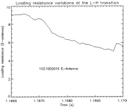
2-1 Typical time evolution of the loading resistance on Alcator C-Mod
during a L to H transition. . . . . 32
2-2 Schematic layout of the impedance matching network in Textor. . . . 34
2-3 Response time of the impedance matching network in Textor. . . . . 35
2-4 Resonant double loop configuration in Tore Supra. . . . . 35
2-5 Variable capacitor used in Tore Supra RDL. . . . . 36
2-6 Cross section schematic of the fast ferrite tuner designed by AFT . . 37
3-1 Cross section of the Alcator C-Mod tokamak. This drawing does not
take into account the modification of the divertor geometry in 2001. . 42
3-2 Top view of the Alcator C-Mod vessel. . . . . 44
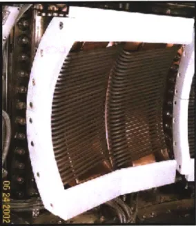
3-3 Picture of D-Antenna as installed in the vacuum vessel. . . . . 45
3-4 Picture of J-Antenna as installed in the vacuum vessel. . . . . 45
3-5 Schematic diagram of the transmission line network for E-Antenna. . 46
3-6 Power and voltage limits in a coaxial line as a function of its impedance. 46 3-7 Loading at DC2 for E-Antenna during the second half of the 2003
campaign. The colors correspond to the aggregated time. . . . . 48
3-8 Loading at DC2 for D-Antenna during the 2002 campaign. . . . . 49
3-9 Loading at DC2 for E-Antenna during the 2002 campaign. The colors
4-1 Resonant double loop antenna schematics (from [2]) . . . . 52
4-2 Conjugate tee network. . . . . 53
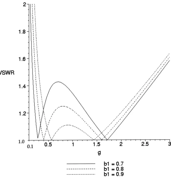
4-3 Calculated VSWR at the feed point for different values of the
normal-ized stub reactance b1 and of the loading conductance g. . . . . 56
4-4 Reflection coefficient at the feed point for different values of the reflec-tion coefficient after the antenna straps. The final reflecreflec-tion coefficient is reduced below 0.2 for the range -0.4 to 0.6 . . . . 57
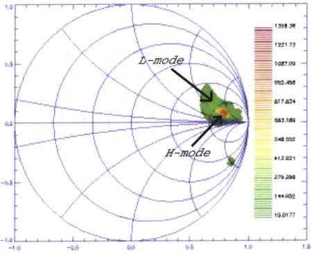
4-5 Smith Chart plot of the reflection coefficient (color) as a function of the load impedance (same parameters as in figure 4-4). We see that the conjugate tee system offers some resilience to load variations in a
large area of the Smith chart. . . . . 59
4-6 Current asymmetry between the two branches. The color represent IL - 11, where I, and 12 are the currents respectively in the top and
bottom branches. . . . . 60
4-7 Generalized conjugate tee configuration using phase shifter-stub tuner
prem atching pairs. . . . . 62
4-8 Initial network layout for evaluation of the load tolerant configuration.
See figure 3-5 for the actual network. . . . . 64
4-9 Simulated reflection coefficient as seen from the transmitter side at
DC1 without the load configuration (figure 4-8). The initial antenna
loading corresponds to figure 3-7. . . . . 64
4-10 Possible configuration for a load tolerant configuration using the
con-jugate tee network, starting from figure 4-8 . . . . 65
4-11 Simulated reflection coefficient as seen from the transmitter side at
DC1 with the load configuration (figure 4-10). The initial antenna
loading correponds to figure 3-7 and is assumed to be unaffected by
the stubs. . . . . 65
4-12 Reflection coefficient at the current-voltage probes for a typical discharge. 66
4-13 Configuration for a load tolerant network for E-Antenna. . . . . 67
4-15 Simulated reflection coefficient at DC2 for a typical discharge -without
current imbalance effects. . . . . 69
4-16 Simulated reflection coefficient at DC2 for a typical discharge - with potential current imbalance effects. . . . . 69
5-1 Schematic layout of phase shifter-stub tuner and double stub tuner matching networks. . . . . 72
5-2 Forbidden area for the double stub matching network. . . . . 73
5-3 Variable impedance phase shifter and stub tuner. . . . . 74
5-4 Reactive component added by the shunt stub as a function of the con-trol parameter b for the example shown here. . . . . 77
6-1 Typical hysteresis curve for ferrite materials. . . . . 83
6-2 Example of initial permeability dependence on permeability, for differ-ent sample temperatures. From [3] . . . . 85
6-3 Schematic two port component. . . . . 89
6-4 Stripline structure between the two coils (in red) (Parts B, C and D). 90 6-5 Initial experiment setup (Part C - Power test). . . . . 91
6-6 S11 attenuation for increasing values of the applied field. . . . . 93
6-7 S21 attenuation for increasing values of the applied field. . . . . 94
6-8 S21 phase for increasing values of the applied field. . . . . 95
6-9 S21 phase shift (from the unmagnetized conditions) for increasing val-ues of the applied field. . . . . 96
6-10 S11 attenuation for the cavity setup, for increasing values of the applied field . . . . 98
6-11 3D view of the stripline used in the experiment, as modeled in CST. 99 6-12 Permeability curve at 80 MHz from experimental phase shift. . . .. 101
6-13 Dielectric constant versus frequency from S11. The central curve cor-responds to p = 35, while the upper (green) and lower curve (red) are p = 20 and p = 50 respectively. . . . . 102
6-14 S11 attenuation comparison at 80 MHz for increasing values of the
applied field. . . . . 103
6-15 S21 attenuation comparison at 80 MHz for increasing values of the
applied field. . . . . 103
6-16 S21 phase shift comparison at 80 MHz for increasing values of the
applied field. . . . . 104
6-17 Loss factor versus frequency and magnetic field from resonator
mea-surem ents. . . . . 105
7-1 Electric field strength in the stripline cross-section for A = 15 . . . . 111
7-2 Electric field strength in the stripline cross-section for / = 3 . . . . . 112
7-3 Phase shift in the stripline section as p is varied. . . . . 113
7-4 Attenuation through the stripline section as p is varied for a 0.02 loss
factor. .. ... ... ... . .. ... ... .. .114
7-5 Cross section of the stripline with permanent magnets (in blue) . . . 115
7-6 Magnetic induction along the red dash line in figure 7-5, at the center. 116
7-7 Magnetic induction along the red dash line in figure 7-5, at the
extrem-ity. . . . . 116
7-8 Drawing of the tuner assembly, with the inner conductor (orange),
ferrite (black), outer conductor (brown) and coils/permanent magnets
List of Tables
2.1 ICRF antenna parameters . . . . 34
Chapter 1
Background and motivations
As physics explored the structure of matter and the interactions which bind its differ-ent constitudiffer-ents, new methods to produce and use energy were successively discovered; they drove and allowed in return sustained industrial and technological development. Fusion is now standing as the current frontier in this process. While its military
applications - the hydrogen bomb - followed quickly the Second World War and the
first use of fission reactions, research on controlled fusion for energy production is still well under way. Fifty years of intense scientific work, after the early attempts of Dr. Lyman Spitzer in the 50's, showed the tremendous difficulty of the effort. Numerous theoretical, experimental and technological problems were encountered, many exper-imental devices built all over the world and much resources spent in a challenging attempt to use on Earth this energy that powers the stars. So far, although no scien-tific evidence suggests that using fusion for energy production is unfeasible, practical applications are still out of our reach and might well be for a least another thirty to
fifty years.
Yet, fusion energy appears more and more as a critical need for our future. All the other sources of energy have limitations in terms of available fuel, production potential or ecological side-effects, while fusion provides electricity and hydrogen fuel very effectively from a virtually infinite reservoir - water - and with little or at least controllable impact of the ecosystem. At the present rate of industrial, economic and population growth, and given the current effects of other sources and estimated
resources, major energy shortages and significant changes in the earth ecological pa-rameters are extremely likely to start occurring within the next fifty years. Although not easy to achieve, fusion energy is an attractive potential solution, and certainly the only one if drastic measures are not taken to reduce significantly the world energy consumption.
This work deals with a very specific and narrow aspect of current fusion research. Although modest, it may help bringing this whole effort a step closer to its goal
-as did and do all the previous and present contributions of the scientists, engineers, technicians in the fusion community.
1.1
Fusion and tokamaks
1.1.1
Fusion energy
Fusion reactions involve bringing together two atomic nuclei. For controlled fusion applications, the most promising involves deuterium and tritium nuclei:
D + T -+ He4 +nu(+17.6MeV)
In this process, 17.6 MeV from nuclear forces are transferred into kinetic energy of the reaction products, but the mutual electrostatic repulsion of the nuclei must be overcome to bring them close enough during a sufficient time for the reaction to occur. This can be achieved by heating a melange containing deuterium and tritium to high temperatures, thus using the thermal velocity to provide the initial energy. The technique is called thermonuclear fusion and requires about 10 keV (figure 1-1).
At these temperatures, the melange is fully ionized and forms a plasma, which must be confined to counteract its rapid thermal expansion. Two techniques are currently being investigated : inertial and magnetic confinement. In inertial con-finement fusion, the D-T melange, initially solid, is embedded into a solid capsule. Typically, a short-pulse high energy laser beam is used to heat the capsule surface and trigger its rapid expansion both outward and inward, which compresses the D-T
tot
10
10 10 1
T(keV)
Figure 1-1: Reaction rate for DT reactions as a function of temperature. From [1]
solid up to pressures and temperatures required for fusion. In magnetic confinement,
magnetic fields are used to maintain the plasma at the center of the device chamber and away from its walls, allowing sufficient densities and temperatures to be reached. By nature, this technique can potentially lead to steady-state self-maintained fusion.
1.1.2
Magnetically confined thermonuclear fusion devices
Determining appropriate magnetic geometries for confinement is not a straightforward issue. Constraints are present for the two possible sources of magnetic field in the plasma - the sets of external coils and the plasma current itself. As the temperature is
increased, significant losses can also occur along the field lines in the magnetic mirror geometry. Historically, these runaway losses, along with various instabilities, limited the maximum temperature and confinement time in early magnetic mirror machines. As the American and European fusion program in the 60's struggled to improve the peak temperatures a 100 eV in mirror machines, Russian scientists reported achieving temperatures of ~ 1 keV in a toroidally symmetrical device, the tokamak, an acronym
of toroidal magnetic chamber in Russian. The torus geometry with a mainly toroidal magnetic field allows field lines to remain in the plasma volume and therefore limits the runaway losses to very high energy particles. But the price to pay is a much more complicated physical and magnetic geometry. The equilibrium and stability for the plasma require complex coil configurations and limits the operating conditions of tokamaks to specific regimes. The rnagnetohydrodynamics (MHD) model has helped gain much intuition and understanding on the underlying physics and has allowed optimization toward better characteristics for fusion. Very successful and promising tokamak operation has been obtained, so that now its design appears as the most likely candidate for commercial fusion devices. As part of the International Thermonuclear Experimental Reactor (ITER) project, ignition should be achieved in a large-size tokamak which is expected to produce thermal energy at the level of an electricity-producing power station. This might be the next and single major step before our level of experience and understanding allow us to build a demonstration electricity-generating power plant (DEMO).
Based on MHD considerations, the magnetic configuration (figure 1-2) used by most present tokamak and retained for the ITER design is a combination of a large toroidal magnetic field - 2-8 Tesla, a smaller poloidal field generated by the toroidal current in the plasma, a vertical field used to control its radial position and different fields which help modifying its shape. A central primary coil is used to generate and control the plasma current. Additional geometrical constraints are associated with the plasma-wall interactions, which can lead to contamination of the plasma volume
by metal impurities from the walls. The diverted configuration, with its characteristic
magnetic x-point in the torus cross-section, is used to prevent the plasma interior from being in direct contact with a solid surface.
Figure 1-2: Schematic drawing of a tokamak.
1.2
Auxiliary heating and Ion Cyclotron
Radio-frequency Heating
1.2.1
Necessity of auxiliary heating
As seen above, the fusion rate is a strong function of temperature. In tokamaks, some form of heating must therefore be provided before the device can reach burning plasma conditions, in which the self-heating from of a-particles resulting from the fusion reactions can balance the power losses.
To increase the plasma temperature close to ignition level, auxiliary heat must be supplied to the plasma. In a tokamak, the toroidal current provides a natural source of plasma heating, called ohmic heating, through the resistance of the plasma, which stems mainly from ion-electron collisions. At low temperatures, ohmic heating can quite strong, but as the ion-electron collision frequency scales as T-1', it decreases strongly as the temperature increases. As losses increase with temperature, ohmic
heating has therefore intrinsic limitations.
A simple calculation can give an order of magnitude of the maximum temperature
in ohmically heated plasmas. Using the Spitzer resistivity and assuming a flat current profile in a circular plasma torus, we can write the ohmic heating power
Pohmic = 7j2 Vtorus = r7j 227 2Ra2 = 2rJ2_
with 77 ~~ 8 x 10⁻⁸T-3/2 the Spitzer resistivity for a pure deuterium plasma, R the major radius, a the minor radius, I the total current and
j
the current density, T the electron temperature in keV.For the prospective ITER parameters, Te = 1 keV and I = 21 MA, this gives
Pohmic ~ 70MW. For Te = 10 keV, the ohmic heating is significantly reduced Pohmic
2.3MW. The radiation and particles losses can be estimated using empirical scalings
for the energy confinement time, Posses = 3nTVtorus, where n is the plasma density.
TE
For ITER, we can take TE"- 6s and r 1 20m-3, so that Posses = Pohmic gives
T ~ 3.2keV.
This is of course a simple estimation, and in practice, more complicated scalings or values for the resistivity and the energy confinement time with non-uniform cur-rent profiles and impurities have to be taken into account. Yet, it turns out that the maximum temperature achievable through ohmic heating for reactor-size devices
remains of the same order. The T- 3/2 dependence of the resistivity is dominant
over the other parameters. In order to reach ignition in a reactor, auxiliary heating sources are therefore required. Neutral beams can be used to introduce fast ions in the plasma and the resulting slowing down transfers the beam energy to the plasma bulk. Another possibility is to use radiofrequency waves launched from the vessel and penetrating into the plasma, where the wave energy can be transferred to the different species in certain conditions. The ion cyclotron radiofrequency heating (ICRH) is one such scheme.
1.2.2
ICRF Heating
The ion cyclotron radiofrequency heating technique takes profit of the damping en-countered by electromagnetic waves as the wave frequency is close to the cyclotron frequency of plasma ion species, which is a associated to their gyration movement in a magnetic field. It has proved very effective for ion heating and presently most of the large and medium-sized tokamaks use multi-megawatt ICRF systems for this purpose. The current status of ICRF physics and technologies will be reviewed in chapter 2, and we summarize here the main points to introduce the objective of this thesis work.
Presently, good theoretical models are available to study and predict wave absorp-tion in the plasma core, and condiabsorp-tions for good absorpabsorp-tion have been determined and successfully realized in experiments. Some issues remain and the complexity of the problem requires numerical treatment, but there is good confidence that the underlying physics is mostly understood, with fair predictive capabilities. The most promising scheme to date uses the fast magnetosonic wave, which can be launched
by inductive loop antennas. Present antenna designs have achieved relatively good
performance, and techniques have been developed to avoid the problems of impurity production or parasitic coupling that occured in early ICRF experiments. While it is still difficult today to predict the effective performance of an antenna design in plasma conditions, most ICRF experiments have been able to reach the point where the antenna geometry and behavior in plasma is no longer the limiting factor for the maximum heating power. Rather, the performance is presently set by available impedance matching techniques. As the fast wave coupling to the tokamak plasma is imperfect and depends on conditions at the edge, the loading resistance of the an-tenna is often low and rapidly varying. The large mismatch between the generator and antenna impedances result in very high voltages in the transmission line network, and electrical breakdown limits the maximum power which can be transferred to the plasma.
possi-ble designs are proposed for the ICRF system in the Alcator C-Mod tokamak. While these upgrades are expected to improve the efficiency and robustness of the ICRF sys-tem in C-Mod, this study is also relevant for future ICRF designs, as novel techniques could be evaluated during tokamak operation in C-Mod. This thesis summaries the approach, results and conclusions, with the following outline :
* Chapter 2 reviews briefly the present status of ICRF physics and technologies, and presents existing impedance matching systems
" Chapter 3 presents the Alcator C-Mod tokamak and its present ICRF system,
and reviews novel techniques for impedance matching for C-Mod.
" Chapter 4 is a study of load tolerant configurations, with a proposed design for
experimental test and evaluation on Alcator C-Mod
* Chapters 5, 6 and 7 present the investigation of ferrite-loaded stripline tuners for fast impedance matching system, and the design of a system using such tuners for Alcator C-Mod.
Chapter 2
ICRH Physics and Technologies
2.1
ICRH Physics
2.1.1
Wave absorption in the ICRF range of frequencies
Waves propagation in tokamak plasma is often very complicated. In general, different species are involved, and the plasma has inhomogeneous two or three-dimensional density, temperature and magnetic field profiles. In addition, the geometry of the tokamak vessel is far from being simple, leading to complex boundary conditions. The response of the plasma species to the wave excitation involves relaxation effects, damping or growth of the wave near resonances. Plasma oscillations are associated with the inertial relaxation of charged species in order to restore quasi-neutrality,
and occur at the plasma frequency w, = n 2 .Ze)The magnetic field introduces
gyration effects with the characteristic cyclotron frequency Q = . As the phase
velocity of waves approaches the harmonics of cyclotron frequencies for the different particles, resonance effects occur. Velocity distribution functions, sometimes different from the usual Maxwellian form, have to be taken into account in the treatment of these effects and this altogether makes most practical situations only approximately tractable with analytical approaches ; numerical codes are required to obtain more accurate and detailed predictions.
still be gained from simplified models. For instance, one can treat the plasma as a zero-temperature frictionless fluid of ions and electron, approximatively charge neutral, homogeneous in space and immersed in a uniform static magnetic field. In this model, called cold plasma model, the wave equation becomes
k x (k x E) + W2c.E = 0
c
where e is the cold plasma dielectric tensor for a magnetic field along the z axis:
S E=iD 0 1 S = -- (R 2 -iD S 0 0 0 P 1 +L),D = -(R - L) 2 R =1-w2 w~+Q 2 L =1+ ( 1j SW(W - Q') 2 P = 1 -S
and the summation index s corresponds to the different species. In the ion
cy-clotron range of frequencies, R ~ (.Qi) and L Eions ( i)'
With these notations, the wave equation can be written, assuming ky = 0 for
simplicity : -iD S - n 2 - n 2 0 nlinL E, 0 Ev = 0 P - n2 E, I
where we introduced nil = -kIi and ni = k i.
S - n 2
iD ni1n1
The dispersion relation is obtained by taking the determinant, leading to
niS i2D _(S __ + p)) 2)p2 _ D 2)=
When the two solutions are well separated, they can be written, with
jSj,
IDJ
<
1PI :
(S-n ,)2 -D2 (Sn 2--D2
n =S-n 2_ 2 S-n - Fast magnetosonic wave
S S-n2 -D 2 Sn
11 PS- 11
nI= (S - n2) D ~ (S - n ) Slow wave
The approximate expressions correspond to SD
<
1, and can be used awayfrom the S = n layer.
At least two properties of the fast magnetosonic waves make it a very good can-didate for radio-frequency heating :
First, its polarization is such that the Ell component of the wave is always small.
In contrary, the slow wave can encounter a resonance - the ion-ion hybrid resonance
- near the plasma edge where the density is low, and there the shielding effects of the electrons is insufficient so that large Ell components are present. We will see the undesirable consequences of this large parallel electric field in the next section. As
the fast wave is primarily a wave with strong E1 component, it can be launched quite
effectively by antennas presenting poloidal currents to the plasma.
Second, the fast wave can be extremely well damped or converted into other well-damped waves in the plasma core. The relevant parameter to quantify this effect is the single-pass absorption which measures the absorbed fraction of the incident power on the absorption region for one pass only, before subsequent reflection of the unabsorbed wave on reflecting cut-off layers or on the vessel walls. Good absorption conditions can be obtained from different schemes, which are now discussed:
Ion cyclotron absorption
The ion cyclotron resonance provides conditions for good absorption depending on the composition of the plasma and the temperature. As the cyclotron frequency increases with the magnetic field, the regions where resonance effects occur depend
on magnetic field profile. The toroidal field is dominant and varies with a good ap-proximation as the inverse of the major radius, therefore defining cylindrical resonant surfaces, where for the cyclotron frequency or its harmonics equals the frequency of the fast wave. Spatial localization for absorption regions can therefore be controlled effectively. However, at low or moderate temperatures, no absorption is encountered at the first harmonics resonance surface for ion species with high concentration. This effect is due to the right-hand polarization of the fast wave at the cyclotron reso-nance, opposite to the free ion motion. Good absorption can be obtained with high
ki waves for higher plasma temperatures, however. Alternatively, higher harmonics
of the cyclotron frequency can also be used for heating.
An alternative scheme using ion cyclotron absorption of the wave can be used with a multi-species plasma. If an ion species with low concentration (minority) is present in a plasma containing other species (majority species) with higher concentration, the fast wave can be strongly damped on the minority ions at their resonance surfaces. The single pass absorption reaches a maximum for a certain minority fraction, usually a few percent.
Direct electron absorption. Mode conversion.
If the plasma temperature is high enough, direct absorption by bulk electrons
can be significant. Transfer of energy from the wave to the electrons can also result from conversion of the fast wave to different waves or modes, like the slow wave, Ion Bernstein wave and Ion Cyclotron wave, which damp strongly on electrons in the plasma core.
These different process allow effective transfer of energy from the wave to the plasma species under a wide range of conditions.
However, fast wave heating techniques are impeded by the presence of an evanes-cent layer at low plasma densities, as can be seen from the dispersion relation (see [4]). This problem and its practical consequences will be examined in section 2.2. Another practical limitation of fast wave heating is related to antenna-plasma interactions.
2.1.2
Antenna-plasma interactions
Early experiments using ICRF antennas reported strong density rise and impurity influxes during ICRF pulses [5] ; the effect could be severe enough to lead to disruptive termination of the discharges. In order to avoid direct contact between the antenna straps and the plasma, and to lower the coupling to the slow wave, a Faraday shield was installed in front of the antenna box, and it was found to have a positive effect on impurity production and heating efficiency during ICRF for low power experiments. Vacuum conditioning of the antenna and wall conditioning were also found to improve
the antenna performance. One of the most important parameters of antenna-plasma behavior, however is the antenna phasing [6] [7]. Two strap or four-strap antennas with adjacent straps driven out of phase have impurity influxes as low as 2% of those in the dipole case, when current straps are driven in phase. The empirical observations above allowed somewhat controlled edge-antenna interactions during ICRF and therefore successful operations of the antennas. The limiting factor for the heating power is now often breakdown limits in the antenna structure or in the transmission line network, as will be presented in the next section, and antennas can operate with little parasitic effect on the plasma discharge.
Different mechanisms have been investigated to explain the observations above. We describe them below, for the low single pass absorption case and the high single pass absorption case.
Low single pass absorption : parasitic modes and far field sheaths [8]
If the single pass absorption is low, the following effects may occur:
(i) The fast wave is not completely absorbed on one pass and therefore encounters the walls or limiters either directly or after multiple reflections on cutoff surfaces.
(ii) Slow waves modes are be generated at the wall or directly for the antenna
(screenless operations).
(iii) Waves with strong Ell components (slow wave, surfaces modes, etc...) drive
All these effects result in increased impurity release from the walls or the limiters.
The dependence on the antenna phasing is due to the fact that waves with higher kl1 are better absorbed in the plasma core, and therefore out of phase phasing should result in higher single pass absorption than in the dipole case.
Good single pass absorption : near field effects, impurity release from the Faraday Shield [9]
Electrons accelerated by the Ell fields lead to rectified sheaths restoring the quasi-neutrality. The associated potentials also have strong gradients in the perpendicular direction, and the resulting electric fields drive E x B convection. As a result of this, ions can be accelerated with energies Ze4b above the sputtering yield of the sheath limiter components. The impurity release is therefore increased. For high single pass absorption, parasitic waves launching can be minimal compared to the net power in the fast wave ; however, as presented in [10], El fields can be generated by r.f. flux
linkage in circuits connecting two points of the Faraday shields along the field line - the
alignment of the shield with the field lines is impossible in practice for all operating condition . This results in significant impurity release from the Faraday shield itself.
By operating with adjacent straps out of phase, the flux linkage potentials can be
canceled or reduced and the impurity release from the shield can be brought down to negligible numbers compared to the dipole phasing.
For high single pass absorption tokamaks, far field effects are minimal, and by driving adjacent straps out of phase, near field effects can be effectively minimized. Therefore, there is little parasitic effect on the discharge, and the most important limitations of the present system arise from impedance matching considerations.
2.2
Impedance matching techniques
2.2.1
The impedance matching problem in ICRH systems
Wave absorption in the ICRF range of frequencies is presently well understood, at least to the extent that conditions for strong absorption of the fast wave are known and can be realized experimentally. However, before reaching the ion cyclotron resonance or mode conversion layer in the plasma core, the fast wave must be launched effectively from the antenna structure. As can be seen from the dispersion relation [4] of the fast wave, an evanescent region is always present in the space between the absorption region and the antenna. The antenna straps are typically isolated from the plasma, and the wave must tunnel through this region before reaching a sufficiently dense plasma where propagation towards the core can occur.
Even with strong single pass absorption, this imperfect coupling limits the amount of power which can be transferred to the plasma for given strap currents. A significant fraction of the power used to maintain the current distribution on the straps is there-fore reflected back toward the generator. This situation is equivalent to the effect of a mismatched termination in the transmission line network, and a commonly used model substitutes the antenna with a lumped load with impedance Zant = R + jX.
Typically R - .5 - 20Q. The characteristic impedance of the coaxial lines in the
network is usually chosen to maximize either the power-carrying capabilities or the breakdown voltage limits, therefore setting Zo in the 25-50 Q range.
This low resistive loading R < ZO results in high voltage standing wave ratio in the lines and potentially at the generator output, which strongly reduce its efficiency. To avoid this undesirable situation, an impedance matching network has to be inserted in the network to isolate the generator from the load. The mismatch can be then effectively reduced on the generator side, but while the net power from the generator equals the power coupled to the plasma at the antenna in steady-state, a significantly higher circulating power is present between the antenna and the impedance matching network, with high VSWR in this section. Electrical breakdown is very likely to occur in the corresponding coaxial lines. Even if the match can be performed as close as
LoadIng rvsistancrc varirtns at the L- transikion
1021D0201l E-Artenna 2.
1 150 1.1570 1.1GO 1 1690 1.1700
nire is)
Figure 2-1: Typical time evolution of the loading resistance on Alcator C-Mod during a L to H transition.
possible to the antenna structure, this limits in practice the maximum power which can be transferred to the plasma.
Another complication arises from the variations in the antenna loading impedance
Zant. Significant and rapid changes in the conditions at the edge of the plasma are
frequent in tokamak operation and it is not clear to date if enough operating range flexibility will be available for final fusion devices in order to avoid these effects. The transition between L and H confinement modes is the source of sudden increases or decreases in the loading resistance, related mainly to the abrupt evolution of the edge density profiles [11]. It occurs on timescales as fast as 10- seconds (figure 2-1). Another source of loading impedance variations is Edge Localized Mode activity.
Presently, most impedance matching networks are adjustable only between dis-charges or slowly during long disdis-charges. Therefore the rapid and significant changes make it impossible for the network to operate with low VSWR at all times. Two directions might be investigated for possible improvements :
short timescales - ideally as fast as 10-4 s.
* Robustness The prematching or matching network is effectively reducing the loading impedance variations so that the mismatch at its feed point remains acceptable, at least for typical load characteristics. Such systems might also be
called tolerant/resilient to load variations.
It is also worth noting that both systems correspond to automatic matching systems, which means that, potentially, the system does not requires the presence of a human operator. This reduces the required manpower to operate the system.
2.2.2
Possible options for fast-matching/robustness
Since the mid 80's and early 90's, several potential fast-matching or resilient systems have been investigated. The most relevant [12] will be described here, as an account for possible options in Alcator C-mod. Most of these systems implement a reactive component with fast tuning capabilities in the transmission line network. Achieving the fastest tuning possible while not compromising other desirable constraints (like the power handling capability, heating efficiency and impurity production control) is the technical challenge that each of these designs has to face, with various aspects involved. The reader may refer to table 2.1 for typical parameters achieved while operating these different systems.
Fast capacitors stub tuner system in Textor
Textor implemented in the early 90's a double stub tuner system using variable ca-pacitors. The system [13] actually consists of a row of two double tuner system (Figure 2-2). From the load to the generator, the first is a traditional slow-moving double tuner system for coarse matching. The second uses small variable capacitors to perform fine fast matching. Each capacitor is positioned by a servo-motor driven mechanism.
The system has been tested for high power operations with plasma loading in
Table 2.1: ICRF antenna parameters
Coupled Power Max Frequency
Tokamak Power (MW) density voltage range
(MW/M2) (kV peak) (MHz) JET (A2) 8-14 2.5 35 25-55 JT-60 U 7 6 35 102-131 Asdex Upgrade 4-6 2.4 26 30-60 Tore Supra 9.5 12-15 45-50 35-80 DIII-D 3.6 3 25 30-60 C-Mod (D,E) 3.5 10 45 80 TEXTOR 3.6 6-10 36 26-38 IVA ^
Figure 2-2: Schematic layout of the impedance matching network in Textor.
TEXTOR Shot 51897 100 0 - --75D nda -5W_ 250 Pam x -0. 0 20 40 80 80 100
Time during the RF pulse (ms)
Figure 2-3: Response time of the impedance matching network in Textor.
Resonant double loop antenna in Tore Supra, TFTR and JET
The resonant double loop (RDL) design is a now well tested antenna scheme which was proposed [2] by Owens at Oak Ridge National Laboratory (ORNL). It is presently used on Tore Supra and is part of ITER-FEAT ICRH antenna design. The time constant for fast matching using tunable stub-tuner phase shifter pairs is typically ~
100 ms, but the system can in principle exhibit a load tolerant behavior which makes
it robust, as will be shown in chapter 4. Furthermore, the matching is realized in the antenna structure itself and therefore the feedthrough and transmission line network
are not exposed to high VSWR (The tore Supra system keep VSWR below 1.2 in
plasma conditions).
wilt
Vacuum
through
Figure 2-4: Resonant double loop configuration in Tore Supra.
A drawing for the presently used tuning capacitors (built by Comet Technick
-Switzerland) is presented in figure 2-5. About 40 units have been used since the
high electrical, thermal and mechanical loading. The dielectric material used will also exposed to high neutron radiation in a burning plasma experiment and therefore the device seems impractical in reactors conditions.
Ball Bearing Cap Orive Screw Nut Mounting Ring Guidiog Tube Shaft Ceramic A ello Fixed Electrode Pumping Tub.
Figure 2-5: Variable capacitor used in Tore Supra RDL.
ITER Design Team is [14] currently working on variants of the presently used RDL structures to replace the lumped tuning components with sections of transmission lines. A prototype ITER-like load tolerant antenna is being designed for JET.
Fast ferrite tuner - Advanced Ferrite Technology
By changing the magnetization of a ferrite material, the electrical length of a
transmis-sion line component can be changed within one to several milliseconds. A matching system using fast ferrite tuners (FFT) has been developed by Advanced Ferrite Tech-nology (AFT) and successfully tested under plasma conditions in ASDEX upgrade,
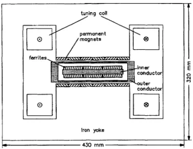
tuning coil permanent magnets ferritess P11111 I W1inner E Iron yoke 430 mm
Figure 2-6: Cross section schematic of the fast ferrite tuner designed by AFT
with a response time of about 4 ms.
A ferrite tuner relies on the change of the magnetic permeability pt in ferrites with an external magnetic field. When a piece of transmission line is partially filled with
ferrimagnetic materials, varying allows to change the electrical characteristics of theA
line, either through the phase velocity v, = j -- or through the boundary conditions. A combination of permanent magnets and magnetic fields coils produces the tuning external field and therefore the electrical length of the line can be adjusted dynam-ically through the current in the coils. The response time of the device, including the data acquisition and control system, is expected to be very low (one to several
milliseconds).
A fast ferrite stub tuner (Figure 2-6) has been developed by the German company Advanced Ferrite Technnologies (AFT) in the early 90's. A double stub tuner system using such devices has been tested under plasma conditions in DiII-D [15] and ASDEX
Upgrade [16] and is to be implemented on ASDEX Upgrade [17]. Under plasma
conditions, an achievable matching speed is ; 500 ms according to these tests. A maximum voltage of 70 KV with 3 bar SF was targeted in the specifications of the initial design.
Liquid stub tuner - LHD
A liquid stub tuner has been developed and implemented on the Large Helical Device
(LHD) [18]. It uses the difference of RF wavelengths between a gas medium and a liquid. By changing the level of the liquid, the electrical length of the device can be varied from 0.26 to 0.45 wavelengths at 36 MHz. An RF power of 1 MW has been transferred to the plasma by a double stub tuner system using such components. The tuners can withstand 63 kV for 10s and 50 kV for 30 minutes. The system has a response time of 7 s, and therefore cannot be considered as a fast-matching option for C-mod.
Traveling wave antenna on DIII-D, JFT-2M
The traveling wave antenna structure [19] is designed to maintain good impedance matching without dynamic tuning during abrupt changes in the antenna loading. Through external components in the transmission line network, the mutual induc-tance of the antenna straps is increased so that the changes in the strap impedance due to the plasma loading evolution are reduced. If the number of straps is sufficient and the array form a set of resonators, all the power is radiated before the traveling wave reaches the end of the structure. The system has a small bandwidth.
The system was implemented and tested on DIII-D [20]. Between 79 and 81
MHz, the reflected power is reduced to 1% to 4 %, showing attractive robustness
without any special fast tuning component. A recirculator circuit is used to reinput the uncoupled power to the TWA structure.
Fast frequency feedback techniques
Another possibility for fast matching relies on fast variations of the generator
fre-quency (typically half a MHz in a few hundred microseconds) . If the length of
the transmission lines in the ICRF network are long enough, varying the frequency changes the effective electrical length of the different sections. This technique effec-tively introduces a fast phase shifter in the system, with a very fast response time.
The JET C and D antennas [21] have been equipped with a system using this technique. The frequency control allows variations as fast as 300 kHZ in 300 Ps. A high characteristic impedance section is used to lower the voltage in the 70 m long transmission line acting as a phase shifter. Finally, an adjustable stub tuner realizes the final impedance matching before the generator. This system is particularly suited to keep the voltage standing wave ratio low during ELM activity.
Before studying the feasibility and attractiveness of these techniques for the Alca-tor C-Mod ICRF system, we will describe the AlcaAlca-tor C-Mod tokamak and its present ICRF systems in the next section.
Chapter 3
Present ICRH system in C-Mod
3.1
The Alcator C-Mod tokamak
3.1.1
Presentation
Alcator C-Mod is the third tokamak of the Alcator series. It started operating at the Massachusetts Institute of Technology in May 1993. It is a compact, high density (up
to 102 1 m-3), high field (up to 8 Tesla) and high power density device, thus exploring
a unique regime in the world fusion program. Typical parameters for Alcator C-Mod discharges are listed in table 3.1. A drawing of the tokamak is shown on figure 3-1.
The vacuum chamber is made of stainless steel and covered with molybdenum tiles. Ten horizontal ports and ten vertical (top and bottom) ports provide access
Table 3.1: Typical parameters of the Alcator C-Mod
Major radius 0.67 m
Minor radius 0.22 m
Toroidal field max 8 T
Elongation 1.6
Triangularity .5
Plasma current max 2 MA
Average density max 102 1m-3
Central electron temperature up to 5 keV
Te -T - Ce"'
----
-
-O
H ~e OH $Nbk pcover Ei EMFigure 3-1: Cross section of the Alcator C-Mod tokamak. This drawing does not take into account the modification of the divertor geometry in 2001.
/~ // / -3- -i - t t I - -- -- - -' - t -- 'Am Z cryewt
to the plasma for diagnostics or auxiliary heating. In addition to the 8 T toroidal field created by the toroidal coils, the plasma shape can be controlled by 4 sets of poloidal coils and its current generated by 3 sets of coils in the central column. All coils are cooled by liquid nitrogen. Both limited and diverted shapes (upper or lower single null and double null) are available. The discharge length is about 2 seconds, during which the required 500 MJ are delivered by an alternator, and about 10 to 20 minutes are needed between discharges both to cool down and to bring the alternator up to speed using electrical power from the grid. Extensive data on different plasma parameters is collected for each discharge by a set of diagnostics devices and made available through the MDS-plus system.
ICRH is the only auxilary heating system in C-Mod, and it is used extensively during experimental campaigns. Currently, three ICRF antennas are installed on the machine, in the D, E and J horizontal ports (figure 3-2). The center-grounded end-fed two-straps antennas at D (figure 3-3) and E port are structurally identical and they operate with fixed dipole phasing at 80.5 and 80 MHz respectively. They have been used since the beginning of the C-Mod tokamak operations in 1994. The antenna at J-port (figure 3-3) is a compact four strap antenna designed and installed in 1998 in collaboration with the Princeton Plasma Physics Laboratory; its operating frequency can be adjusted between 40 and 80 MHz by using an appropriate setup for the transmitters and the transmission line network. Different phasings can be used for J antenna, like (0,7r,0,7r), (0,0,0,0), (0,7r,7r,0), (0,7r/2,7r,3wr/2), and can be used for heating or current drive. Details on the antenna structure and geometry can be found in [22).
Investigation and understanding ICRF heating and current drive is one of the primary objectives of the Alcator C-Mod program ; this includes gaining experience and knowledge in the design and operation of reliable and efficient RF launchers and transmission systems. This present work is part of this effort. Among the other proposed upgrades to the RF system in Alcator, we can mention the design and implementation of a new four strap antenna at E-port, which will replace the existing
E F D & E-port antennas
D G
GH Full Limiter C
AB Split L iter J-port antenna
B
A K
Figure 3-2: Top view of the Alcator C-Mod vessel.
3.1.2 Present ICRF system
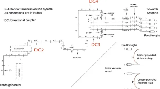
Transmission of the ICRF power from the source to the antenna uses a network of low loss coaxial transmission lines (figure 3-5. Copper is used for the inner conductor while the outer is either copper or aluminum. Close to the antenna structure, high pressure sulfur hexafluoride SF gas is injected after pumping and maintained around 3 bar, which substantially increases the breakdown limits in the corresponding sections. Teflon spacers are used all along the network to hold the central conductor in place. From the transmitter to the antenna feedthrough, the outer to inner diameter ratio in the coaxial lines is set with various combinations so that the impedance of the lines is 50 Q, which corresponds to a good trade-off between power-carrying limits and breakdown limits (fig. 3-6).
The behavior of the network is monitored by a set of directional couplers (DCs), with typically -60 to -70 dB attenuation for the measured direction and -90 dB for the reverse direction. Pairs of such couplers located at the same location give forward and reflected power measurements. The phase is obtained through demodulators boards, and the three channels are digitized to the acquisition system. In addition
Figure 3-3: Picture of D-Antenna as installed in the vacuum vessel.
0
DC4
E-Antenna transmission line system 2 12
All dimensions are in inches 8 ASSTOP
DC: Directional coupler t 6 2 2 22 876 22132G3 TOP2 12 12 2 12 1 8 12 -287 1 72 1 143 22 1 22 2A
I PHASE SHIFTER _JI12
C
8 12 24 12
I"
IIC Inside vac
vessel Towards generator uum 2 602 Towards Antenna 13 6 TOP 6 6 6 60220T1M 6 Feedthroughs Feedthroughs Center grounded Antenna strap Center grounded Antenna strap
Figure 3-5: Schematic diagram of the transmission line network for E-Antenna.
2so 4so6 100
Chaaveiski impedance (Ohms)
B"MWkOMn ImIt
--- Pan oruie opil
.. .. .. .. . l W 0 a
Figure 3-6: Power and voltage limits in a coaxial line as a function of its impedance.
to directional couplers, voltages probes and some current probes are also present at specific locations. Typically, measurements are done close to the high voltages points,
as permitted by possible physical layouts of the sections.
The impedance matching uses a stub tuner/phase shifter pair, which is adjustable
3.8-
between discharges. The phase-shifter/stub tuner matching network will be presented in chapter 5.
Different arc detection systems were initially available on the C-Mod ICRF net-work [23]. They rely on logarithmic demodulator modules with different voltage/current probe or directional coupler positions. High VSWR, high reflected wave power or phase differences induced by arcing can be tracked by the modules, and the excita-tion from the transmitter can be removed within 10 Ms. Although phase difference faults are present in the system, usually arcs manifest themselves through the in-creased VSWR in the matched part of the network. This method is robust and reliable, although in principle high current point arcs remain undetected in principle. Inspection of lines suggest that most breakdown occurrences take place near high voltages points or at insulating surfaces, and therefore the present system is effective in limiting their effect.
3.1.3
Typical loading variations for D and E antennas
Currently, the antenna loading resistance is low compared to the characteristic impedance in the transmission lines and corresponds to reflection coefficient around 0.8 in the unmatched part of the network, with some variations both in magnitude and phase during the discharges. By tuning the phase shifter-stub tuner for average conditions within this range, this mismatch can be reduced in the transmitter side of the network, allowing acceptable high power operations ; the typical reflected power on the trans-mitter side is less than 5 % in most conditions. However, the unmatched part is still subject to high VSWR and strong circulating power, and residual loading variations with plasma conditions lead to a still significant loss of power from the unmatched
reflected power, namely up to 5-10 %. The variations of the coupling with the plasma
parameters have been studied in 2001 and 2002 for the three antennas in C-Mod. Typical Smith Chart loadings at DC2 are shown on fig 3-8 and 3-9 for D and E antennas. The variations of the loading impedance of the antenna are restricted to a small area of the Smith Chart. The loading impedance at DC2 varies from 5 to 10 Q for both D and E.
![Figure 1-1: Reaction rate for DT reactions as a function of temperature. From [1]](https://thumb-eu.123doks.com/thumbv2/123doknet/14686065.560282/20.918.273.650.120.515/figure-reaction-rate-dt-reactions-function-temperature.webp)