Publisher’s version / Version de l'éditeur:
Vous avez des questions? Nous pouvons vous aider. Pour communiquer directement avec un auteur, consultez la première page de la revue dans laquelle son article a été publié afin de trouver ses coordonnées. Si vous n’arrivez pas à les repérer, communiquez avec nous à [email protected].
Questions? Contact the NRC Publications Archive team at
[email protected]. If you wish to email the authors directly, please see the first page of the publication for their contact information.
https://publications-cnrc.canada.ca/fra/droits
L’accès à ce site Web et l’utilisation de son contenu sont assujettis aux conditions présentées dans le site LISEZ CES CONDITIONS ATTENTIVEMENT AVANT D’UTILISER CE SITE WEB.
Internal Report (National Research Council of Canada. Division of Building
Research), 1983-11-01
READ THESE TERMS AND CONDITIONS CAREFULLY BEFORE USING THIS WEBSITE.
https://nrc-publications.canada.ca/eng/copyright
NRC Publications Archive Record / Notice des Archives des publications du CNRC :
https://nrc-publications.canada.ca/eng/view/object/?id=f1e5fb0d-8651-48ee-bc77-fc1de4489330 https://publications-cnrc.canada.ca/fra/voir/objet/?id=f1e5fb0d-8651-48ee-bc77-fc1de4489330
NRC Publications Archive
Archives des publications du CNRC
For the publisher’s version, please access the DOI link below./ Pour consulter la version de l’éditeur, utilisez le lien DOI ci-dessous.
https://doi.org/10.4224/40001325
Access and use of this website and the material on it are subject to the Terms and Conditions set forth at
Fire tests on reinforced concrete columns: specimen no. 9
ltef
Ser
IT H I
National Research
Conseil national
K427
I
Council Canada
de recherches Canada
n. 486
,
FIRE TESTS ON REINFORCED CONCRETE COLUMNS, SPECIMEN NO. 9
by
T.T. Lie and T.D. Lin
Private copy
for:
N I C
-
b t 6 T IBLDG.
RES.
LIBRARY
84-
Dl-
3
1
s t e t ~ o ~ n t
QUE
Rech.
Blirim.
..
,. .
DBR
Internal Repon 486 / / / / , //,,*A/
NATIONAL RESEARCH COUNCIL OF CANADA DIVISION OF BUILDING RESEARCH
DBR INTERNAL REPORT NO. 486
FIRE TESTS ON REINFORCED CONCRETE COLUMNS, SPECIMEN NO. 9 by T.T. Lie and T.D. Lin
Checked by: T
.
2 .H.
Approved by: L. W . Gold Date: November 1983Prepared for: Record Purposes
ABSTRACT
Results of a fire test on a reinforced concrete column are given. The test is one of a series of twelve tests carried out in the first phase of a joint study on the fire performance of concrete columns by the National Research Council Canada and the Portland Cement Association. The column was made with siliceous aggregate.
LLS
secLion size was305
x305
mnl(12
x12
in.). It was tested to investigate the influence of load on the fire resistance of the column.FIRE TESTS ON REINFORCED CONCRETE COLUMNS SPECIMEN NO. 9
by
T. T. L i e and T. D. Lin*
T e s t s were c a r r i e d out on a s e r i e s of r e i n f o r c e d c o n c r e t e columns a s p a r t of a s t u d y t o develop methods f o r t h e d e t e r m i n a t i o n of t h e f i r e r e s i s t a n c e of such columns. The s t u d y was a c o o p e r a t i v e e f f o r t between t h e N a t i o n a l Research C o u n c i l Canada and t h e P o r t l a n d Cement
A s s o c i a t i o n . I n t h e f i r s t phase of t h e s t u d y 12 columns were t e s t e d . The columns were d e s i g n e d and manufactured by PCA i n Skokie, U.S.A., and t e s t e d i n t h e NRCC l a b o r a t o r i e s i n Canada. The specimens, method of t e s t i n g and t e s t r e s u l t s a r e d e s c r i b e d i n s u c c e s s i v e r e p o r t s .
T h i s r e p o r t d e a l s w i t h specimen No. 9, which was t e s t e d t o i n v e s t i g a t e t h e i n f l u e n c e of l o a d on t h e f i r e r e s i s t a n c e of t h e column.
The test specimen c o n s i s t e d of a s q u a r e t i e d r e i n f o r c e d c o n c r e t e column. D e t a i l s of t h e specimen and i t s f a b r i c a t i o n a r e g i v e n below.
D i m e n s i o n s
S e c t i o n s i z e : 305 x 305 mm (12 x 12 i n . ) Height: 3810 mm (12 f t 6 i n . )
Materiala
Cement: Type I , a g e n e r a l purpose cement f o r t h e c o n s t r u c t i o n of r e i n f o r c e d c o n c r e t e s t r u c t u r e s .
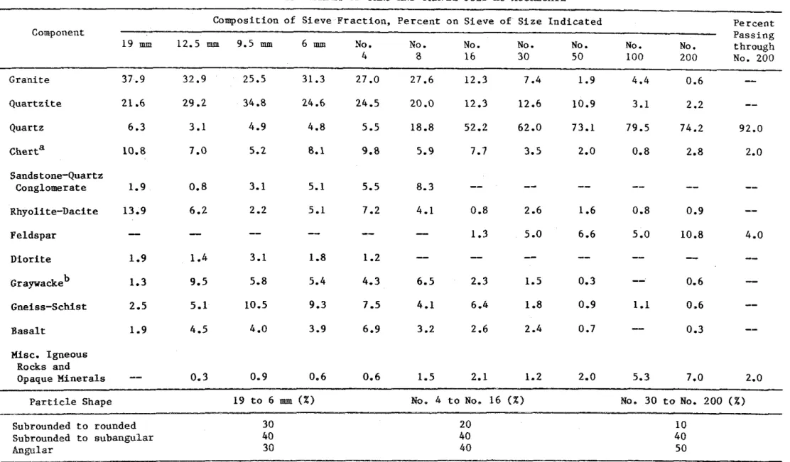
Aggregate: S i l i c e o u s sand and g r a v e l from Eau C l a i r e , Wisconsin. The maximum s i z e of t h e a g g r e g a t e was 19 mm (314 in.). The g r a d a t i o n curve i s shown i n F i g u r e 1. P e t r o r a p h i c i n f o r m a t i o n on t h e a g g r e g a t e ,
7
o b t a i n e d a c c o r d i n g t o ASTM C295-79
,
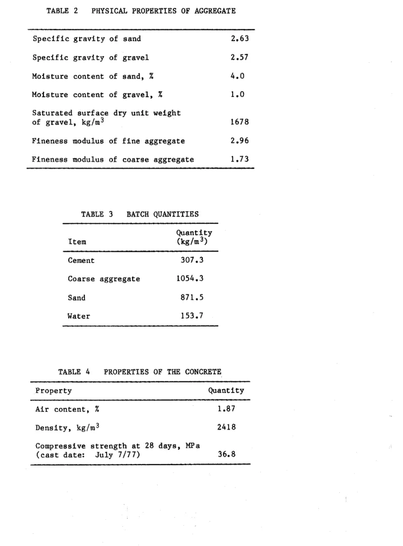
i s g i v e n i n T a b l e 1. The p h y s i c a l p r o p e r t i e s of t h e a g g r e g a t e a r e g i v e n i n Table 2.S t e e l r e i n f o r c e m e n t : Deformed 25M (No. 8 ) l o n g i t u d i n a l
r e i n f o r c i n g b a r s and 10M (No. 3 ) t i e s meeting t h e r e q u i r e m e n t s of ASTM D e s i g n a t i o n ~ 6 1 5 - 6 0 2 were used. The y i e l d s t r e n g t h of t h e 25M b a r s was 443.7 MPa (64.3 k s i ) and t h a t of t h e 10M b a r s 426.5 MPa (61.8 k s i ) . The u l t i m a t e s t r e n g t h s of t h e 25M and 10M b a r s were 730 MPa (105.8 k s i ) and 671 MPa (97 k s i ) r e s p e c t i v e l y .
*Senior r e s e a r c h e n g i n e e r , P o r t l a n d Cement A s s o c i a t i o n , Skokie, I l l i n o i s .
Concrete mix: The c o n c r e t e mix was designed t o produce a 34.5 MPa (5000 p s i ) s t r e n g t h n o n - a i r - e n t r a i n e d c o n c r e t e . A water-cement r a t i o of 0.6 was used. The slump was 10 mm (3.92 i n . ) . Batch q u a n t i t i e s a r e g i v e n i n T a b l e 3 and measured p r o p e r t i e s of t h e c o n c r e t e i n T a b l e 4.
Fabrication
C a s t i n g
The column was c a s t i n a s p e c i a l l y designed form. A t t h e s t a r t of t h e c a s t i n g t h e f r o n t s i d e of t h e form was l e f t open f o r d e p o s i t i n g f r e s h c o n c r e t e . The c o n c r e t e was mixed i n a 0.17 m 3 (6 f t 3, t i l t i n g drum mixer. Shovels and scoops were used t o d e p o s i t c o n c r e t e i n t h e form. A s m a l l i n t e r n a l v i b r a t o r was a p p l i e d t o c o n s o l i d a t e t h e c o n c r e t e . As t h e c a s t i n g p r o g r e s s e d upwards, t h e window p i e c e s were s u c c e s s i v e l y c l o s e d and t i g h t l y b o l t e d t o t h e form t o a v o i d p o s s i b l e m o i s t u r e l e a k s . L i f t i n g hooks were embedded on o p p o s i t e s i d e s of t h e t e s t specimen a t 800 mm ( 2 f t 7 112 i n . ) from t h e t o p of t h e column. A c y l i n d r i c a l humidity w e l l 3 w i t h a d i a m e t e r of 4 mm (5132 i n . ) was
p o s i t i o n e d a t mid-height of t h e column f o r measuring t h e r e l a t i v e humidity a t mid-depth.
R e i n f o r c i n g cage
The r e i n f o r c i n g cage was assembled by welding each end of f o u r l o n g i t u d i n a l main r e i n f o r c i n g b a r s t o a s t e e l end p l a t e . The b a r s were c u t t o 3800 mm (12 f t 5 112 i n . ) and machined a t b o t h e n d s , f o r a
l e n g t h of 19 mm (314 i n . ) t o a d i a m e t e r of 19 mm (314 i n . ) . F i g u r e 2 shows d e t a i l s of t h e f i n i s h e d b a r s . The dimensions of t h e end p l a t e s were 533 x 533 x 25 mm (21 x 21 x 1 i n . ) . I n e a c h c o r n e r of t h e p l a t e , 20.6 cm h o l e s (13116 i n . ) were d r i l l e d t o accommodate t h e l o n g i t u d i n a l b a r s . The c e n t e r s of t h e h o l e s were s p a c e d 92.1 mm ( 3 518 i n . ) from t h e c e n t e r l i n e s of t h e p l a t e s . I n t h i s way a column was o b t a i n e d w i t h a s e c t i o n of 305 x 305 mm (12 x 12 i n . ) and a c o v e r of 47.6 mm
( 1 718 i n . ) t o t h e main r e i n f o r c i n g b a r s and 38.1 mm ( 1 112 i n . ) t o t h e s t i r r u p s . The main b a r s and s t i r r u p s were t i e d t o g e t h e r t o complete t h e s t e e l cage which, i n c l u d i n g t h e s t e e l p l a t e s , was 3810 mm
(12 f t 6 i n . ) long. Welding
The p r o v i s i o n s of AWS D e s i g n a t i o n ~ 1 2 . 1 - 7 5 were followed when welding p l a t e s and b a r s . These members were p r e h e a t e d w i t h a propane
t o r c h t o 288'C (550°F), t o p r e v e n t b r i t t l e f a i l u r e d u r i n g welding. The s i d e f i l l e t weld was done around b a r s on t h e i n n e r f a c e of t h e bottom p l a t e . McKay E10018-D2 and DYTRON-579 welding r o d s were used. Both
t y p e s of welding r o d s have t e n s i l e s t r e n g t h of 834.9 MPa (121 000 p s i ) . M i l d - s t e e l welding r o d s were used t o f i l l up t h e 6 mm (114 i n . ) deep h o l e s on t h e o u t e r f a c e s of t h e p l a t e . The rough s u r f a c e s of t h e welded j o i n t s on t h e o u t e r f a c e of t h e p l a t e were ground t o a smooth f i n i s h .
The top s t e e l p l a t e was welded a f t e r t h e c a s t i n g of t h e columns. Before p o s i t i o n i n g t h e t o p p l a t e , a 6 mm (114 i n . ) l a y e r of mortar was spread over t h e t o p of t h e column t o e n s u r e good c o n t a c t between s t e e l and c o n c r e t e . The m o r t a r was made of one p a r t cement and t h r e e p a r t s s i l i c e o u s sand. Using t h e same procedure a s f o r t h e bottom p l a t e , t h e t o p p l a t e was welded on t h e o u t e r s i d e t o t h e b a r s and smoothed.
Curing
The c o n c r e t e was cured under damp b u r l a p f o r s e v e n days a t 21 t o 24'C (70 t o 75'F). The form was t h e n s t r i p p e d , and t h e column
c o n d i t i o n e d i n an atmosphere c o n t r o l l e d a t 21 t o 24'C (70 t o 75OF) r e l a t i v e humidity. The column was removed from t h e k i l n p e r i o d i c a l l y t o c o o l a t 23OC (73'F) s o t h a t t h e r e l a t i v e humidity i n t h e c o n c r e t e c o u l d be measured.
Two hundred s i x t y days a f t e r t h e column was c a s t , t h e r e l a t i v e humidity i n t h e c e n t e r of t h e column reached 87X, and t h e column was wrapped i n p l a s t i c t o p r e v e n t change i n i t s m o i s t u r e c o n t e n t .
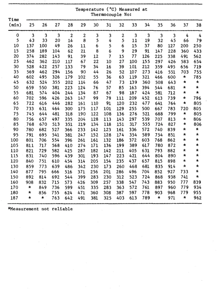
Butt-welded chromel-alumel thermocouples 0.912 mm t h i c k (0.0359 i n . ) were used t o make thermocouple frames f o r measuring
c o n c r e t e t e m p e r a t u r e s a t d i f f e r e n t l o c a t i o n s i n v a r i o u s c r o s s s e c t i o n s of t h e columns. Each frame c o n s i s t e d of a number of thermocouples t i e d t o s t e e l r o d s t h a t were f i r m l y secured t o t h e main r e i n f o r c i n g bars. The thermocouples were a r r a n g e d t o measure t e m p e r a t u r e s a t t h r e e l e v e l s : a t one-quarter h e i g h t , a t mid-height and a t t h r e e - q u a r t e r h e i g h t of t h e column. A t mid-height t h e t e m p e r a t u r e s were measured a l o n g t h e whole l e n g t h of a c e n t e r l i n e and a d i a g o n a l of t h e s e c t i o n ; a t t h e o t h e r two l e v e l s t h e t e m p e r a t u r e s w e r e measured o n l y a l o n g h a l f of t h e c e n t e r l i n e and h a l f of t h e d i a g o n a l of t h e s e c t i o n . The
l o c a t i o n s of t h e thermocouples i n t h e c o n c r e t e and t h e i r numbering a r e shown i n F i g u r e s 3 and 4.
I n a d d i t i o n , a number of thermocouples were mounted on t h e
r e i n f o r c i n g s t e e l b a r s and ties. The l o c a t i o n s of t h e thermocouples on t h e s t e e l a r e shown i n F i g u r e 5 and i n more d e t a i l i n F i g u r e 6. A l l thermocouples were i n s t a l l e d i n such a way t h a t t h e w i r e f o l l o w e d a n i s o t h e r m f o r a t l e a s t 12.7 mm (112 i n . ) from t h e j u n c t i o n .
Test Apparatus
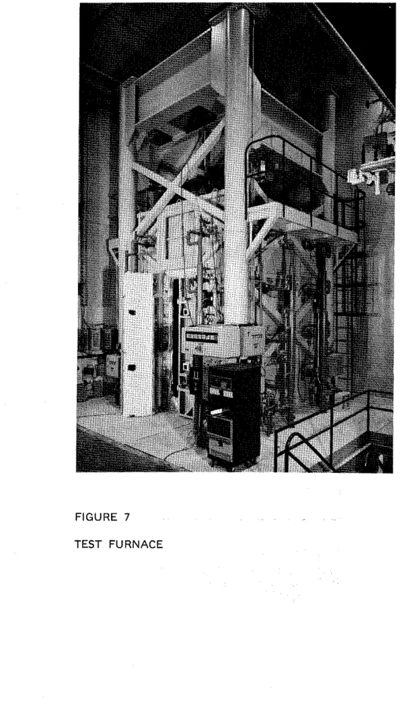
The t e s t was c a r r i e d o u t by exposing t h e column t o h e a t i n a
f u r n a c e s p e c i a l l y b u i l t f o r t e s t i n g l o a d e d coluimns and w a l l s . The t e s t f u r n a c e was designed t o produce t h e c o n d i t i o n s t o which a member might be exposed d u r i n g a f i r e ; f o r example, f i r e t e m p e r a t u r e s , s t r u c t u r a l l o a d s , and h e a t t r a n s f e r . It c o n s i s t s of a s t e e l framework s u p p o r t e d by f o u r s t e e l columns w i t h t h e f u r n a c e chamber i n s i d e t h e framework ( F i g . 7). The c h a r a c t e r i s t i c s and i n s t r u m e n t a t i o n of t h e f u r n a c e a r e
d e s c r i b e d i n d e t a i l i n r e f e r e n c e 5. Only a b r i e f d e s c r i p t i o n of t h e f u r n a c e and t h e main components w i l l be given here.
Loading Device
Three h y d r a u l i c j a c k s produce f o r c e s a l o n g t h e t h r e e p r i n c i p a l axes. The j a c k a c t i n g a l o n g t h e a x i s of t h e t e s t column i s l o c a t e d a t t h e bottom of t h e f u r n a c e chamber. The p l a t e on t o p of t h i s j a c k can be used a s a p l a t f o r m t o which t h e column can b e a t t a c h e d .
Furnace Chamber
The f u r n a c e chamber h a s a f l o o r a r e a of 2642 x 2642 mm
( 8 f t 8 i n . x 8 f t 8 i n . ) and i s 3048 mm (10 f t ) high. It i s made of i n s u l a t i n g m a t e r i a l s t h a t w i l l produce a h i g h h e a t t r a n s f e r t o t h e specimen. There a r e 32 propane g a s b u r n e r s i n t h e f u r n a c e chamber, a r r a n g e d i n e i g h t columns, c o n t a i n i n g f o u r b u r n e r s each. The t o t a l c a p a c i t y of t h e b u r n e r s
i s
4700kW
(16 x l o 6 Btufh). Each b u r n e r c a n be a d j u s t e d i n d i v i d u a l l y t o o b t a i n a h i g h t e m p e r a t u r e u n i f o r m i t y i n t h e f u r n a c e chamber. The p r e s s u r e i n t h e f u r n a c e chamber i s a l s oa d j u s t a b l e . It was s e t somewhat lower t h a n atmospheric p r e s s u r e .
Instrumentation
The f u r n a c e t e m p e r a t u r e s were measured w i t h t h e a i d of e i g h t chromel-alumel thermocouples. The j u n c t i o n of e a c h thermocouple was l o c a t e d 305 mm ( 1 f t ) from t h e t e s t specimen, a t v a r i o u s h e i g h t s . Two thermocouples were p l a c e d o p p o s i t e e a c h o t h e r e v e r y 610 mm (2 f t ) a l o n g t h e h e i g h t of t h e f u r n a c e chamber. The l o c a t i o n s of t h e i r j u n c t i o n s and t h e i r numbering a r e shown i n F i g u r e 8. Thermocouples Nos. 4 and 6 were l o c a t e d a t
a
h e i g h t of 610 mm ( 2 f t ) from t h e f l o o r , thermocouples Nos. 2 and 8 a t 1220 mm (4 f t ) , thermocouples Nos. 3 and 5 a t 1830 mm(6 f t ) and thermocouples Nos. 1 and 7 a t 2440 mm (8 f t ). The
t e m p e r a t u r e s measured by t h e thermocouples were a v e r a g e d a u t o m a t i c a l l y and t h e average t e m p e r a t u r e was used a s t h e c r i t e r i o n f o r c o n t r o l l i n g t h e f u r n a c e temperature.
The l o a d s were c o n t r o l l e d and measured w i t h p r e s s u r e t r a n s d u c e r s . The a c c u r a c y of c o n t r o l l i n g and measuring l o a d s was a b o u t 5% a t lower load l e v e l s and b e t t e r a t h i g h e r l o a d s .
The a x i a l d e f o r m a t i o n of t h e test specimen was determined by measuring t h e d i s p l a c e m e n t of t h e j a c k t h a t s u p p o r t s t h e column. The displacement was measured u s i n g t r a n s d u c e r s w i t h an a c c u r a c y of
0.002 mm.
Test Conditions and Procedure
The column was i n s t a l l e d i n t h e f u r n a c e by b o l t i n g i t s end p l a t e s t o a l o a d i n g head a t t h e t o p and a h y d r a u l i c j a c k a t t h e bottom. For t h i s purpose e i g h t 19 mm (314 i n . ) b o l t s spaced r e g u l a r l y around t h e column 63.5 mm (2 112 i n . ) from t h e s i d e s were u s e d a t e a c h end.
On t h e day of t h e t e s t , t h e m o i s t u r e c o n d i t i o n i n t h e c e n t e r o f t h e column was measured w i t h a Monfore gauge.3 The r e l a t i v e humidity measured p r i o r t o t h e s t a r t of t h e test was 75%. The ambient
temperature a t t h e s t a r t of t h e t e s t was 6.0°C (4Z°F).
The column was c a s t on 16 August, 1977 and t e s t e d on 5 February, 1981. It was s u b j e c t e d t o a l o a d of 1333 irN (300 k i p s ) a p p l i e d a b o u t one hour b e f o r e t h e test. A t t h e t e s t d a t e , t h e c y l i n d e r s t r e n g t h s of t h e c o n c r e t e measured on two c y l i n d e r s were 39.7 MPa (5757 p s i ) and 37.0 MPa (5359 p s i ) r e s p e c t i v e l y .
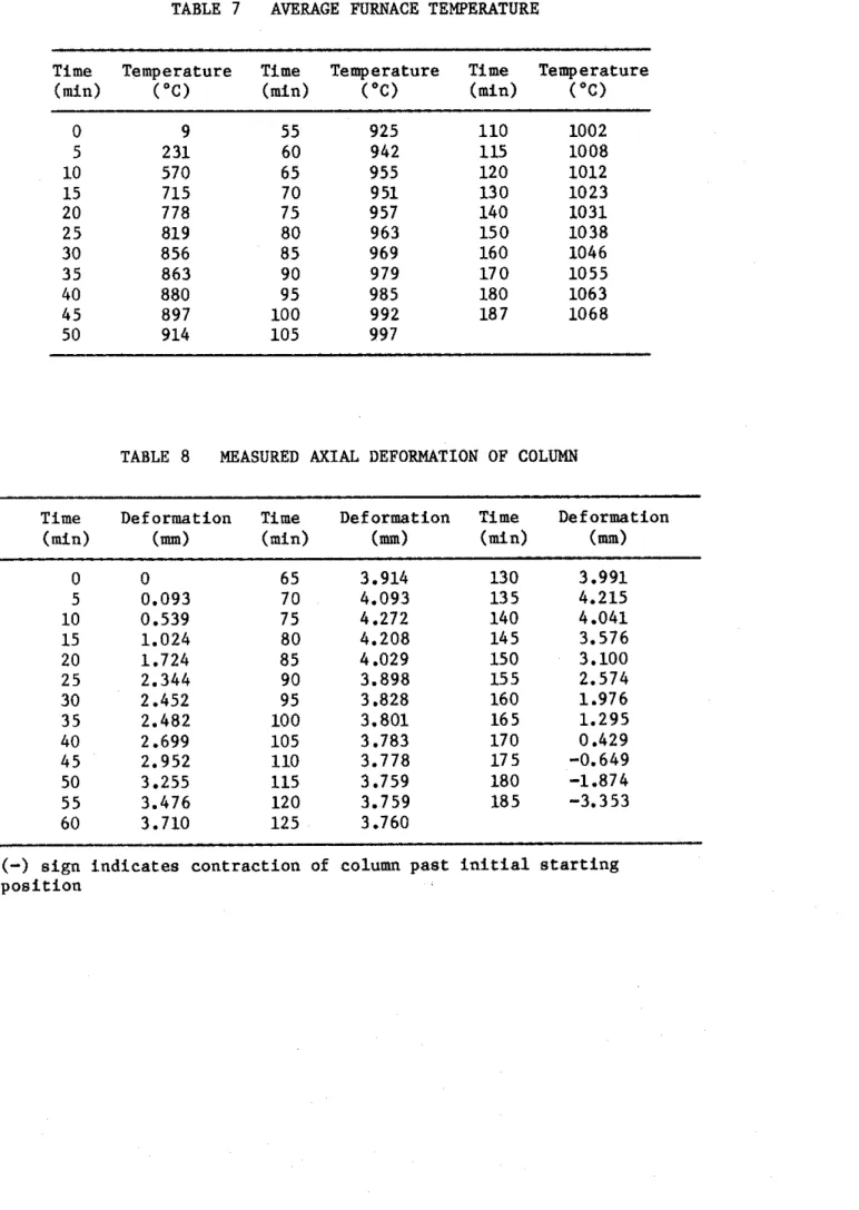
During t h e t e s t t h e column was exposed t o h e a t i n g c o n t r o l l e d s o t h a t t h e average temperaure i n t h e f u r n a c e followed a s c l o s e l y a s p o s s i b l e t h e A S T M - E ~ ~ ~ ~ o r U L C - S ~ O I ~ s t a n d a r d temperature-time curve. T h i s c u r v e can be approximately d e s c r i b e d by t h e f o l l o w i n g equation:
Tf = 20
+
750 [1-exp(-3.79553Si)l+
1 7 0 . 4 1 G (1) where Tf = temperature i n O C , and T = t i m e i n h Tf = 68+
1350 [l-exp(-3.79553431+
3 0 6 . 7 4 6 where Tf = temperature i n OF.During t h e t e s t , temperatures i n t h e f u r n a c e and i n t h e column were measured a t t h e l o c a t i o n s d e s c r i b e d e a r l i e r . The a x i a l
deformation of t h e column was a l s o measured. The column was c o n s i d e r e d t o have f a i l e d and t h e t e s t was t e r m i n a t e d when t h e h y d r a u l i c j a c k , which has a maximum speed of 76 mm/min ( 3 in./min), could no l o n g e r m a i n t a i n t h e load.
TEST
BESLILTSMeasured Temperaturea and Deforratlona
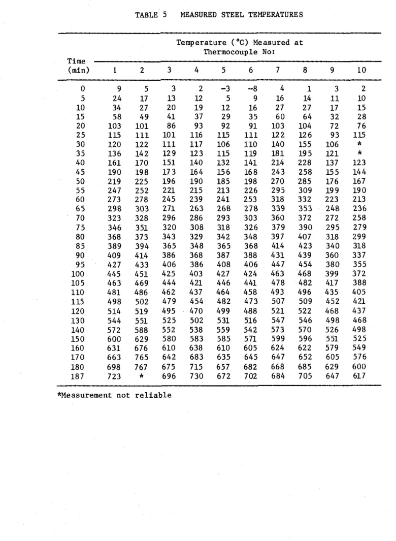
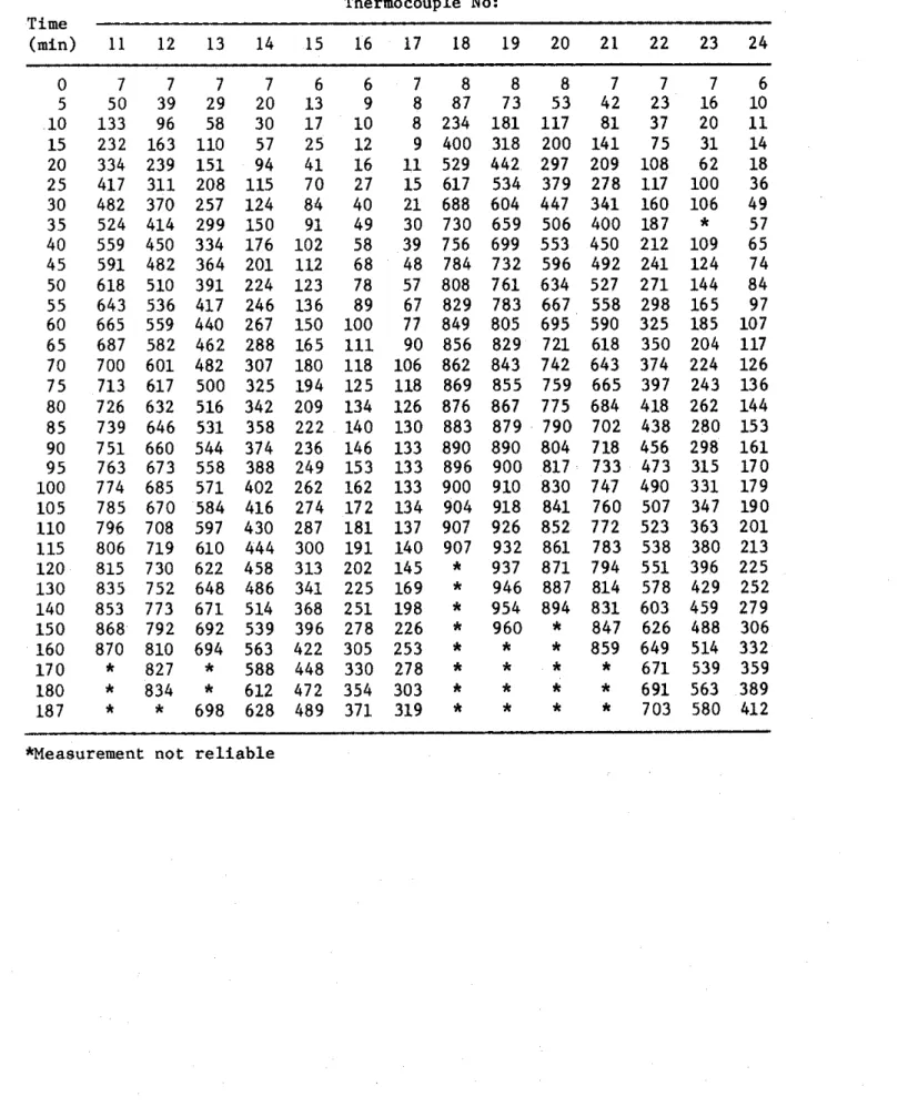
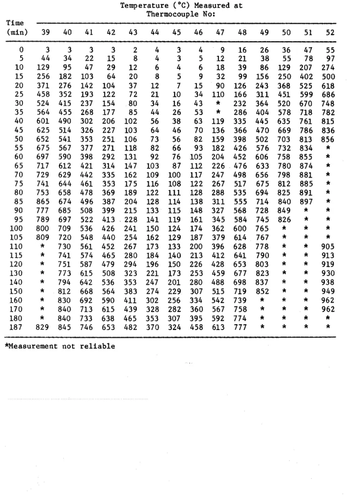
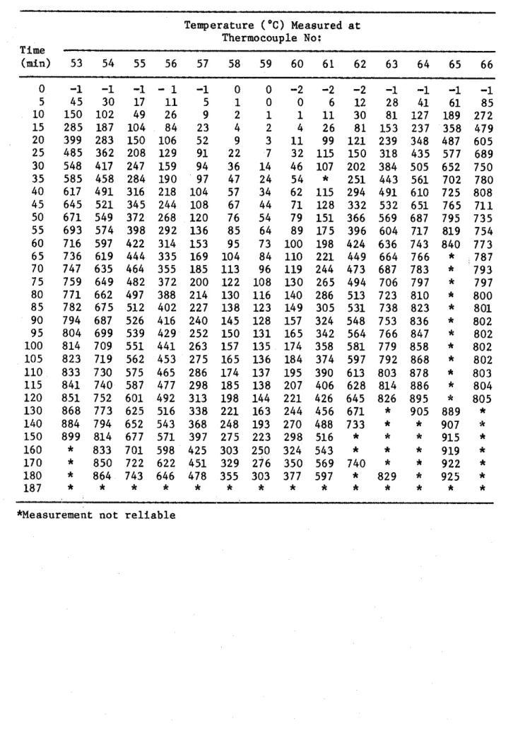
I n Table 5 t h e s t e e l temperatures a r e g i v e n f o r v a r i o u s times. The temperatures measured i n t h e c o n c r e t e s e c t i o n s a r e g i v e n i n T a b l e s 6A-D .
I n Table 7 t h e a v e r a g e f u r n a c e temperature and i n Table 8 t h e measured a x i a l d e f o r m a t i o n of t h e column a r e g i v e n f o r v a r i o u s t i m e s d u r i n g t h e t e s t .
Observations
Specimen was t e s t e d t o s i m u l a t e a n i n t e r i o r column exposed t o f i r e on f o u r s i d e s . A 1333 kN (300 k i p ) l o a d was c o n c e n t r i c a l l y a p p l i e d t o t h e column.
A crack was seen 30 minutes a f t e r t h e f i r e s t a r t e d on t h e n o r t h s u r f a c e of t h e column, a b o u t 60
cm
(2 f t ) from t h e f u r n a c e c e i l i n g .A t 2 h c r a c k s developed on a l l s i d e s of t h e column. The l a r g e s t c r a c k was l o n g e r t h a n 90 cm ( 3 f t ) and n e a r l y 6 mm (114 in.) wide. The t e s t column f a i l e d i n compression a t 3 h 7 min. I n Fig. 9, a p i c t u r e of t h e column, t a k e n immediately afte3r t h e t e s t ,
i s
shown.DISCUSSIOU OF RESULTS
The method d e s c r i b e d i n r e f e r e n c e 9 was used t o c a l c u l a t e t h e t e m p e r a t u r e s of t h e main r e i n f o r c i n g s t e e l , and t h e t e m p e r a t u r e s a t v a r i o u s d e p t h s i n t h e c o n c r e t e s e c t i o n s . For t h e r e i n f o r c i n g s t e e l t h e t e m p e r a t u r e a t t h e c e n t e r h a s been chosen a s r e p r e s e n t a t i v e of t h e average t e m p e r a t u r e of t h e s t e e l . The two a v e r a g e t e m p e r a t u r e s
o b t a i n e d from measurements on two r e i n f o r c i n g b a r s d u r i n g t h e t e s t a r e shown i n F i g u r e 10. These measurements were made w i t h thermocouples Nos. 3 and 9 , l o c a t e d o p p o s i t e e a c h o t h e r w i t h r e s p e c t t o t h e c e n t e r of one b a r , and w i t h thermocouples Nos. 4 and 1 0 , l o c a t e d o p p o s i t e each o t h e r on a n o t h e r b a r ( s e e Fig. 6). The a v e r a g e measured s t e e l
t e m p e r a t u r e s and t h e a v e r a g e s t e e l t e m p e r a t u r e c a l c u l a t e d a c c o r d i n g t o t h e method d e s c r i b e d i n r e f e r e n c e 9 a r e compared i n F i g u r e 10. The comparison shows r e a s o n a b l y good agreement between measured and c a l c u l a t e d t e m p e r a t u r e s .
The t e m p e r a t u r e s measured on t h e s t e e l by t h e i n d i v i d u a l thermocouples are shown i n F i g u r e 11.
The t e m p e r a t u r e s shown i n F i g u r e 12 were measured a l o n g a
c e n t e r l i n e i n t h e c o n c r e t e s e c t i o n a t v a r i o u s depths. The c u r v e s shaw t h a t c a l c u l a t e d t e m p e r a t u r e s a r e somewhat h i g h e r t h a n measured
t e m p e r a t u r e s .
I n F i g u r e 1 3 t h e measured a x i a l d e f o r m a t i o n d u r i n g t h e t e s t and t h o s e c a l c u l a t e d u s i n g t h e method d e s c r i b e d i n r e f e r e n c e 9 a r e shawn. A f t e r a t e s t i n g t i m e of about 1 h , t h e c a l c u l a t e d t e m p e r a t u r e s a r e n o t i c e a b l y l o w e r t h a n t h e measured temperature. The c a l c u l a t e d f a i l u r e time was 156 min, which
i s
about 19% lower t h a n t h e measured f a i l u r e t i m e of 193 min.1.
Standard Practice for Petrographic Examination of Aggregates for
Concrete (1979).
ASTM C295-79, American Society for Testing and
Materials, Philadelphia, PA.
2.
Standard Specification for Deformed and Plain Bullet-Steel Bars for
Concrete Reinforcement (1980).
ASTM A615-80, American Society for
Testing and Materials, Philadelphia, PA.
3. Monfore, G.E. (1962).
A Small Probe-Type Gauge for Measuring
Relative Humidity. Journal of the PCA Research and Development
Laboratories, Vol. 5, No. 2.
4.
Reinforcing Steel Welding Code (1975).
AWS-D12.1-75, American
Welding Society, Manlius, NY.
5. Lie, T.T.
(1980).
New Facility to Determine Fire Resistance of
Columns, Canadian Journal of Civil Engineering, Vol. 7, No.
3.6. Standard Methods of Fire Tests of Building Construction and
Materials (1979).
ANSIfASTM E119-79, American Society for Testing
and Materials, Philadelphia, PA.
7. Standard Methods of Fire Endurance Tests of Building Construction
and Materials (1980).
ULC-SlOl-Ml980. Unde~writers'
Laboratories
of Canada, Scarborough, Ontario.
8.
Lie, T.T. and Harmathy, T.Z. (1972).
A Numerical Procedure to
Calculate the Temperature of Protected Steel Columns Exposed to
Fire. Fire Study No. 28, Division of Building Research, National
Research Council of Canada, Ottawa, Ontario, NRCC 12535.
9.
Lie, T.T., Allen, D.E., Lin, T.D. and Abrams, M.S.
Fire Resistance
of Reinforced Concrete Columns, Division of Building Research,
National Research Council of Canada, Ottawa, to be published.
TABLE 1 P E T R O G W W OF SAND AND GRAVEL USED AS AGGREGATE
Composition of Sieve Fraction, Percent on Sieve of Size Indicated Percent
Component Passing
19 mm 12.5 mm 9.5 mm 6 nun No. No. No. No. No. No. No. through
4 8 16 30 50 100 200 No. 200 Granite 37.9 32.9 25.5 31.3 27
.O
27.6 12.3 7.4 1.9 4.4 0.6-
Quartzite 21.6 29.2 34.8 24.6 24.5 20.0 12.3 12.6 10.9 3.1 2.2--
Quartz 6.3 3.1 4.9 4.8 5.5 18.8 52.2 62.0 73.1 79.5 74.2 92.0 Sandstone-Quartz Conglomerate 1.9 0.8 3.1 5.1 5.5 8.3--
--
--
--
--
--
Rhyolite-Dacite 13.9 6.2 2.2 5.1 7.2 4.1 0.8 2 -6 1.6 0.8 0.9--
Feldspar-
-
--
-
--
-
1.3 5 .O 6.6 5.0 10.8 4.0 Diorite 1.9 1.4 3.1 1.8 1.2-
-
--
--
--
-
--
Graywadre b 1.3 9.5 5.8 5.4 4.3 6.5 2.3 1.5 0.3--
0.6-
Gneiss-Schist 2.5 5.1 10.5 9.3 7.5 4.1 6.4 1 .8 0.9 1.1 0-6--
Basalt 1.9 4.5 4.0 3.9 6.9 3.2 2.6 2.4 0.7-
0.3--
Wise. Igneous Rocks and Opaque Minerals--
0.3 0.9 0.6 0.6 1.5 2.1 1.2 2.0 5.3 7.0 2.0Particle Shape 19 to 6 nun
( % I
NO. 4 to No. 16 (%) No. 30 to No. 200 (%)Subrounded to rounded 30 20 10
Snbrounded to subanylar 40 40 40
Angular 30 40 50
a. Ironstone," made up of jasper and hematite, is included in the chert classification. ?Includes metagraywadre.
%he miscellaneous lgseous rocks were severely altered and posieive identification was irgosible. The opaque minerals occurred in the No. 50 a ~ d smaller sieve sizes and were largely magnetite.
TABLE 2 PHYSICAL PROPERTIES OF AGGREGATE S p e c i f i c g r a v i t y of sand 2.63 S p e c i f i c g r a v i t y of g r a v e l Moisture c o n t e n t of sand, % Moisture c o n t e n t of g r a v e l , % 1.0 S a t u r a t e d s u r f a c e dry u n i t weight of g r a v e l , kg/m3 1678 F i n e n e s s modulus of f i n e a g g r e g a t e 2.96 F i n e n e s s modulus of c o a r s e a g g r e g a t e 1.73
TABLE 3 BATCH QUANTITIES Q u a n t i t y Item (kg/m3) Cement 307.3 Coarse a g g r e g a t e 1054.3 Sand 871.5 Water 153.7
TABLE 4 PROPERTIES OF THE CONCRETE
P r o p e r t y Q u a n t i t y
A i r c o n t e n t , X 1.87
D e n s i t y , kg/m3
Compressive s t r e n g t h a t 28 d a y s , MPa
TABLE 5 MEASURED STEEL TEMPERATURES Temperature ( " C ) Measured a t Thermocouple No: Time (mid 1 2 3 4 5 6 7 8
9
10 *Measurement not r e l i a b l eTABLE 6A CONCRETE TEMPERATURES MEASURED WITH THERMOCOUPLES IN
FRAME
A Temperature ( O C ) Measured a t Thermocouple No: Time (min) 1 1 12 13 14 15 16 17 18 19 20 21 22 23 24 *Measurement not r e l i a b l eTABLE 6B CONCRETE TEMPERATURES MEASURED WITH THERMOCOUPLES I N FRAME B Time (min)
-
0 5 1 0 15 20 2 5 30 3 5 40 45 50 5 5 60 65 7 0 75 80 8 5 90 9 5 100 105 110 115 120 130 140 150 160 170 180 187Temperature (OC) Measured a t
Thermocouple No: 29
-
2 8 11 21 3 9 67 79 90 102 114 124 134 147 l b l 175 190 204 219 233 247 261 274 287 301 314 342 371 399 426 451 471 491 *Measurement n o t r e l i a b l eTABLE 6C CONCRETE TEMPERATURES MEASURED
WITH
THERMOCOUPLES I N FRAME C Temperature ( " C ) Measured a t Thermocouple No: Time (min) 39 40 41 42 43 44 45 46 47 48 49 50 51 52 0 3 3 3 3 2 5 44 34 22 15 8 10 129 95 47 29 1 2 15 256 182 103 64 20 20 371 276 142 104 37 25 458 352 193 122 72 30 524 415 237 154 80 35 564 455 268 177 85 40 601 490 302 206 102 45 625 514 326 227 103 50 652 541 353 251 106 55 675 567 377 271 118 60 697 590 398 292 1 3 1 65 717 612 421 314 147 70 729 629 442 335 162 75 741 644 461 353 175 80 753 658 478 369 189 8 5 865 674 496 387 204 90 777 685 508 399 215 95 789 697 522 413 228 100 800 709 536 426 241 105 809 720 548 440 254 110*
730 561 452 267 115*
741 574 465 280 120*
751 587 479 294 130*
773 615 508 323 140*
794 642 536 353 150*
812 668 564 383 160*
830 692 590 411 170*
840 713 615 439 180*
840 733 638 465 187 829 845 746 653 482 Weasurement n o t r e l i a b l eTABLE 6D CONCRETE TEMPERATURES MEASURED WITH THERMOCOUPLES I N FRAME D Temperature ('C) Measured a t Thermocouple No: T i m e ( m i d 53 54 55 56 57 58 59 60 61 62 63 64 65 66 0 -1 -1 -1 - 1 -1 0 0 -2 -2 -2 -1 -1 -1 -1 5 45 30 17 11 5 1 0 0 6 12 28 41 61 85 10 150 102 49 26 9 2 1 1 11 30 8 1 127 189 272 1 5 285 187 104 84 23 4 2 4 26 8 1 153 237 358 479 20 399 283 150 106 52 9 3 11 99 121 239 348 487 605 25 485 362 208 129 91 22 7 32 115 150 318 435 577 689 30 548 417 247 159 94 36 14 46 107 202 384 505 652 750 35 585 458 284 190 97 47 24 54
*
251 443 561 702 780 40 617 491 316 218 104 57 34 62 115 294 491 610 725 808 45 645 521 345 244 108 67 44 71 128 332 532 651 765 711 50 671 549 372 268 120 76 54 79 151 366 569 687 795 735 55 693 574 398 292 136 8 5 64 89 175 396 604 717 819 754 60 716 597 422 314 153 95 73 100 198 424 636 743 840 773 65 736 619 444 335 169 104 84 110 221 449 664 766*
787 70 747 635 464 355 185 113 96 119 244 473 687 783*
793 75 759 649 482 372 200 122 108 130 265 494 706 797*
797 80 771 662 497 388 214 130 116 140 286 513 723 810*
800 8 5 782 675 512 402 227 138 123 149 305 531 738 823*
801 90 794 687 526 416 240 145 128 157 324 548 753 836*
802 95 804 699 539 429 252 150 1 3 1 165 342 564 766 847*
802 100 814 709 551 441 263 157 135 174 358 581 779 858*
802 105 823 719 562 453 275 165 136 184 374 597 792 868*
802 110 833 730 575 465 286 174 137 195 390 613 803 878*
803 115 841 740 587 477 298 185 138 207 406 628 814 886*
804 120 851 752 601 492 313 198 144 221 426 645 826 895*
805 130 868 773 625 516 338 221 163 244 456 671*
905 889*
140 884 794 652 543 368 248 193 270 488 733*
*
907*
150 899 814 677 571 397 275 223 298 516*
k*
915*
160*
833 701 598 425 303 250 324 543*
*
*
919*
170*
850 722 622 451 329 276 350 569 740*
*
922*
180*
864 743 646 478 355 303 377 597*
829*
925*
187*
*
x*
*
*
x*
*
x x x x x *Measurement n o t r e l i a b l eTABLE 7 AVERAGE FURNACE TEMPERATURE
Time Temperature Time Temperature T i m e Temperature
( m i d ("C) b i n ) ( " 0 b i n ) ("C)
TABLE 8 MEASURED AXIAL DEFORMATION OF COLUMN
Time Deformation Time Deformation Time Deformation
( m i d (mm) ( m i d (mm) (mm)
- - - - - -- - - -
-
s i g n i n d i c a t e s contraction of column past i n i t i a l s t a r t i n g p o s i t i o n100
50
30
16
84
9 . 5
1 9
3 7 . 5
m m
m r n
m m
S T A N D A R D S I Z E O F S Q U A R E M E S H S I E V E
F I G U R E 1
P L A T E
P L A T E
F I G U R E
2T / C F R A M E A
27
S E C T I O N A - A
T / C
F R A M E B
O N B A C K
TIC
F R A M E C
ON F R O N T -
S E C T I O N B - B
T / CF R A M E D
@I
S E C T I O N C - C
TIC
F R A M E
F I G U R E
3
L A Y O U T O F T H E R M O C O U P L E F R A M E S
TIC
FRAME 17 16 15 14 13 1 2 1 1 A 3130
29 28 27 26 25B
45 44 43 42 4140
39 C 59 58 57 56 55 54 53D
F I G U R E 4 L O C A T I O N A N D N U M B E R S O F T H E R M O C O U P L E S I N A S E C T I O N48 mm CLEAR COVER TO MAIN REINFORCING BAR
TIC
4, 5, 6, 104 25 M BAR 3 5 m m
TIC
1, 2. 3. 9305 mm 533 x 533
x
25 mmTHICK STEEL PLATE 7 I
F I G U R E 5
S E C T I O N A - A S E C T I O N 5 - 6 ( F R O N T ) I F R O N T I S E C T I O N C - C S E C T I O N D - D I I ( F R O N T ) ( F R O N T ) F R O N T O R D O O R S I D E F R O M T H E T O P F I G U R E 6 T H E R M O C O U P L E S O N R E I N F O R C I N G B A R S ( 3 0 5 rnrn x 3 0 5 rnrn C O L U M N )
FIGURE 7 TEST FURNACE
T O P V I E W 1 . 2 C O L U M N 5 , 6 F U R N A C E 3 , 4 C H A M B E R 7, 8 I I I D O O R ( E A S T S I D E ) F I G U R E 8 L O C A T I O N A N D N U M B E R S O F T H E R M O C O U P L E S I N C O L U M N F U R N A C E C H A M B E R
FIGURE 9
T I M E , m i n F I G U R E 10 C A L C U L A T E D A N D M E A S U R E D A V E R A G E T E M P E R A T U R E S OF M A I N R E I N F O R C I N G B A R S T I M E , rnin F I G U R E 11 T E h l ? t R A T j R E S Y F A S J R I D OI\ f:Al\ R E t f . F O i l U I l G B A R S
C A L C U L A T E D M E A S U R E D 0 1 0 0 2 0 0 T I M E , w i n F I G U R E 1 2 C O N C R E T E T E M P E R A T U R E S I N M I D - H E I G H T S E C T I O N A L O N G C E N T R E L I N E A T V A R I O U S D E P T H S C A L C U L A T E D