Publisher’s version / Version de l'éditeur:
Journal of the Acoustical Society of America, 104, July 1, pp. 266-274, 1998-07-01
READ THESE TERMS AND CONDITIONS CAREFULLY BEFORE USING THIS WEBSITE. https://nrc-publications.canada.ca/eng/copyright
Vous avez des questions? Nous pouvons vous aider. Pour communiquer directement avec un auteur, consultez la
première page de la revue dans laquelle son article a été publié afin de trouver ses coordonnées. Si vous n’arrivez pas à les repérer, communiquez avec nous à PublicationsArchive-ArchivesPublications@nrc-cnrc.gc.ca.
Questions? Contact the NRC Publications Archive team at
PublicationsArchive-ArchivesPublications@nrc-cnrc.gc.ca. If you wish to email the authors directly, please see the first page of the publication for their contact information.
Archives des publications du CNRC
This publication could be one of several versions: author’s original, accepted manuscript or the publisher’s version. / La version de cette publication peut être l’une des suivantes : la version prépublication de l’auteur, la version acceptée du manuscrit ou la version de l’éditeur.
For the publisher’s version, please access the DOI link below./ Pour consulter la version de l’éditeur, utilisez le lien DOI ci-dessous.
https://doi.org/10.1121/1.423277
Access and use of this website and the material on it are subject to the Terms and Conditions set forth at
Effect of electrical outlet boxes on sound insulation of a cavity wall
Nightingale, T. R. T.; Quirt, J. D.
https://publications-cnrc.canada.ca/fra/droits
L’accès à ce site Web et l’utilisation de son contenu sont assujettis aux conditions présentées dans le site LISEZ CES CONDITIONS ATTENTIVEMENT AVANT D’UTILISER CE SITE WEB.
NRC Publications Record / Notice d'Archives des publications de CNRC:
https://nrc-publications.canada.ca/eng/view/object/?id=2b585ffc-eeeb-4109-8c94-926b63657fe1 https://publications-cnrc.canada.ca/fra/voir/objet/?id=2b585ffc-eeeb-4109-8c94-926b63657fe1
Effect of electrical outlet boxes on sound insulation of a cavity wall
Nightingale, T.R.T.; Quirt, J.D.
NRCC-41912
A version of this document is published in / Une version de ce document se trouve dan
Journal of the Acoustical Society of America, v. 104, no. 1, July 1998, pp. 266-274
EFFECT OF ELECTRICAL OUTLET BOXES ON SOUND INSULATION OF A CAVITY WALL
T.R.T Nightingale, J.D. Quirt Acoustics Laboratory
Institute for Research in Construction, National Research Council Canada
K1A 0R6
Suggested PACS numbers: 43.55.Rg
ABSTRACT
The results of a systematic study investigating the effect on the sound insulation of wood stud walls having penetrations made by electrical outlet boxes are presented. The effect on sound insulation is shown to be almost negligible, regardless of box separation, if the boxes are themselves airtight and form an airtight seal with the gypsum board surfaces. However, if the boxes are not airtight, then the degradation to the sound insulation is strongly dependent on the separation between the boxes. Other significant factors include the presence of cavity absorption, and its method of
installation. A series of retrofits for poorly installed boxes is examined and show that commonly available devices for reducing airflow (and sound insulation) through electrical boxes can be very effective but are highly dependent on installation.
INTRODUCTION
Many authors have studied the effect of penetrations in walls in the form of slits or cylinders both experimentally and analytically. In previous studies of penetrations through walls, two simplifications were common:
a) The penetration can be treated as a cylinder1, 2 or slit3,4 (in the case of
the slit a further restriction is usually added requiring the length to be much greater than the width),
b) The wall is monolithic such that the slit or cylinder is continuous and vented only to the source and receive side of the wall. Mechel5, 6
provided a theoretical description which included addition of a fibrous absorbing material of variable airflow resistance in the penetration. But again, the penetration did not vent into a cavity. Most of the work on slits originated from investigations of door and window seals.
These previous studies have indicated that penetrations through walls in the form of slits or cylinders can be very detrimental to the sound insulation especially for frequencies above the quarter wavelength frequency
corresponding to the depth of the slit or cylinder.
This may have helped the growth of the generally accepted feeling that the presence of closely spaced electrical outlet boxes in a party walls can degrade the sound insulation.
In a limited set of double leaf walls containing cavity absorption, Royle7
investigated the effect of slits around a wall’s perimeter, as well as
penetrations by a cylinder and by back-to-back electrical boxes. It was shown experimentally that the type of wall penetration or “leak” affects the sound insulation in different ways, indicating that work for slits and cylinders might not be applicable to outlet boxes. Royle concluded from the work done with walls containing cavity absorption that penetrations by back-to-back electrical boxes did not present a serious problem if the wall cavity contained glass fiber insulation, 80 mm thick.
In this paper, which presents a systematic study of the factors affecting the sound insulation of gypsum board cavity walls having penetrations in the form of electrical boxes (see Figures 1 and 2), it is shown that the offset distance between penetrations is only one factor and is often of secondary importance. Royle’s conclusion regarding offset distance is shown to be correct for a subset of the cases considered in his study, but in general the conclusion is not valid.
TEST SPECIMENS
The study examined the reduction in sound insulation caused by installing electrical outlet boxes in two types of load-bearing wood framed party walls that nominally (i.e. without penetrations) provide a sound insulation greater
than STC 50. The wall details, the box locations, and the nomenclature to identify box locations are given in Figures 1 and 2 for the double- and single-stud framing types considered, respectively.
All the walls had gypsum board surfaces and 38x89 mm wood studs separated 400 mm o.c. The wall specimens were 3.05 m wide and 2.44 m high and were installed in the specimen frame between the reverberation chambers of the Institute for Research in Construction (IRC) at the National Research Council of Canada (NRCC). The electrical boxes were positioned with the bottom of each box approximately 300 mm from the bottom of the wall. All wiring needed to simulate normal field installation was installed. These specimens allowed for a systematic investigation of the following factors:
• Box type (standard metal box or plastic box with a built-in air barrier, see Figure 3);
• Box placement (back-to-back, same cavity or adjacent stud cavity, Figures 1 and 2) for the two wall constructions;
• Box treatment including gaskets to seal the opening and inserts or other materials for lining the boxes;
• Baffles in the wall cavity to block line-of-sight between boxes;
• Possible structural vibration transmission through the electrical boxes when the gypsum board is mounted on resilient channels;
• Frequency dependence of the sound insulation degradation due to boxes of various dimensions.
The tests to assess the sound insulation of each assembly were conducted in accordance with the requirements of ASTM E90-19908, Standard Method for
Laboratory Measurement of Airborne Sound Transmission Loss of Building Partitions. The Sound Transmission Class (STC) was determined in
accordance with ASTM Standard Classification E413-19909.
The test procedure was designed to optimize the accurate comparison
between the different electrical outlet positions for the same wall specimen. For the two types of framing considered, a base wall specimen was
constructed with no penetrations and the sound insulation was measured. The gypsum board was removed and saved for later re-installation.
The four or five electrical outlet boxes, complete with duplex outlets, face plates, and associated wiring were installed in accordance with the Canadian Electrical Code10 (which is essentially equivalent to the National Electrical
Code11 used in the USA). Holes were cut in the gypsum board to
accommodate the boxes and the gypsum board was re-installed. The
openings in the gypsum board for each outlet were masked with covers made from a double layer of 12.7 mm thick gypsum board that overlapped about 25 mm beyond the edges of the opening. A 3 mm neoprene gasket formed an air-tight seal between the masks and the gypsum board. The masks were held in place by screws into the threaded tabs of the electrical box. With the masks installed, the wall was re-tested.
In all cases considered in this study, the difference between the result with all the outlets masked and the original result (with no penetrations) was less than the known reproducibility uncertainty associated with removing and replacing a layer or layers of gypsum board in the IRC laboratory, r95 2 dB or
2 STC points for lightweight walls. (This value not only contained any effect due to fabrication anomalies but also uncertainties associated with the test method which are laboratory dependent.) This small uncertainty justified
using the case with no penetrations as the reference case relative to which the results with various outlet configurations were assessed.
Duplex electrical outlet fittings and cover plates were then installed and tested for each outlet configuration in turn, with the other outlet positions masked. This masking technique allows the examination of many different box locations without reconstructing the wall specimen, thus enabling accurate measurement of changes in sound insulation resulting from small changes to the location and/or treatment(s) of the electrical outlet.
FACTORS AFFECTING SOUND INSULATION
The key factors affecting the sound insulation of wood stud walls with electrical outlets were systematically investigated. Unless otherwise noted the electrical boxes under test were fitted with duplex electrical outlet fittings and face plates.
Effect of Box Type
Two types of boxes were investigated: standard metal boxes, and plastic vapor barrier boxes. Typical installation details are shown in Figure 3. Standard metal boxes (nominal dimensions: height, 75 mm; width, 47 mm; depth, 63 mm) were used in all specimens, unless specifically noted. (Later the frequency dependence of the degradation will be related to the
dimensions of the box.) The metal boxes had over-sized cable penetrations and mounting holes on the back side of the box which permitted free
movement of air in and out of the box. These penetrations represent about 370 mm2 or about an 11% open area when normalized to the area of the face
of the box in the plane of the wall.
Plastic vapor barrier (PVB) boxes are designed to be placed in walls where maintaining the integrity of the air/vapor barrier is important (e.g. exterior
walls). The boxes tested had total dimensions of 140 mm height, 105 mm width, 75 mm depth. Like the metal boxes, they were mounted to the studs using nails and were able to accept four NMD type cables. In the case of the PVB boxes, a closed-cell foam membrane provided an airtight seal around cable(s) inserted into the box.
The greatest difference in overall air-tightness arises from the method of sealing the box to the gypsum board wall surface. In the case of the metal boxes, the nominal 6—12 mm gap between the gypsum board cutout and the box remains unsealed; this represents an open area of 1000 – 2200 mm2. The
PVB boxes utilize a backer plate that is 25 mm larger than the outside box dimensions, with closed cell foam to form an airtight seal with the gypsum board. If the cutout in the gypsum board is sized properly then the opening will be completely covered when the faceplate is installed. However, this may not always be the case and will be shown later to cause some variability in the effectiveness of retrofit techniques for poorly placed boxes.
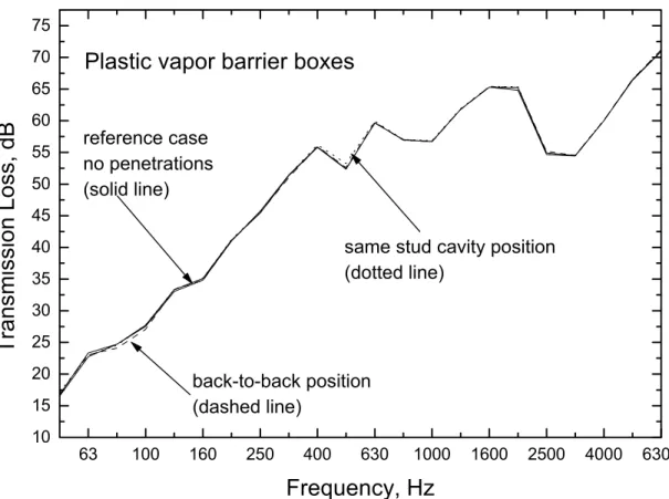
The sound insulation for standard metal boxes without any treatment was compared to that with the PVB boxes, when installed in the double wood stud wall without cavity absorption (a sensitive case). The results are shown in Table 1. The plastic boxes provided consistently better sound insulation than the untreated metal boxes, especially in the back-to-back configuration. The transmission loss data shown in Figure 4 indicate that the sound insulation of a party wall with plastic boxes installed in any position, even back-to-back, was nearly identical to that without any penetrations.
The correlation between air-tightness and sound insulation has been
employed by several authors12,13 as a method of estimating the degree of
air-tightness of the separating building element(s).
To establish the effect of different types of electrical fittings, single toggle light switch fittings were installed in the same metal boxes of the double
wood stud wall. Figure 5 shows that the transmission loss of the wall
assembly for the two types of fittings is similar in the ranges 63-500 Hz and 2.5-6.3 kHz. However, there is a marked difference in the range
800-1250 Hz; the wall containing the light switches offers up to 15 dB better performance. This may be attributed to the fact that the light switch assembly does not have penetrations, quite unlike the duplex outlet which has 6 holes to accept the prongs of two electrical plugs.
Thus, if electrical boxes can be made relatively airtight, there is negligible effect. This should not be surprising, as Mechel5 has previously shown
numerically that even a very light weight impervious material at either end of a penetration can improve the sound reduction significantly. However, when the installed boxes are not airtight and allow the unimpeded passage of air (i.e., the metal boxes with the duplex outlets) the effect on the sound insulation can be significant.
Box Placement and Cavity Absorption
The degradation of sound insulation that was observed when electrical boxes were placed in the back-to-back configuration in a double wood stud wall is shown in Figure 5. The effect is strongest in the frequency range around 1 kHz, where an 18 dB degradation was observed. This is much greater than the 6 point reduction in STC would suggest. The change in the sound
insulation in the 1 to 2 kHz frequency range will be shown to be a function of the box dimension and is discussed later.
Table 2 shows the change in sound insulation relative to the reference case, without penetrations, for various locations of the untreated metal boxes. From the table it can be seen that the effect of electrical boxes on the sound insulation of a wall can be large and the reduction in the sound insulation depends on several factors: the separation (horizontal offset) of the electrical boxes, the construction of the wall, and the location of wall cavity absorption.
Within the scope of this study, these cannot be fully separated, but general trends can be identified.
The greatest reduction of the STC occurred when there was a short
unimpeded path between boxes — that is, the sound did not have to travel through the cavity absorption (or in the case of the double wood stud wall through the 25 mm gap between studs into the next cavity). This is shown by the reduced sound insulation for walls with boxes in the back-to-back and same cavity positions without cavity absorption, and the back-to-back position with the batts displaced around the boxes as shown in Figure 1b. Conversely, when the sound energy must travel through, or at grazing incidence to, the cavity absorption (i.e. all other absorption cases), the effect is greatly reduced.
Table 2 and Figure 6 show the change in sound insulation for the double stud wall with cavity absorption installed in two ways: displaced around the side of the box or placed completely over the back of the box. The table shows that having the layer of cavity absorption between back-to-back electrical boxes greatly minimizes the reduction in the STC rating. This is not surprising since for each 90 mm thickness of glass fiber building insulation that the sound energy passes through the sound energy may be attenuated by as much as 10 dB at 1000 Hz.
It is evident from Table 2 that when the boxes are offset by 350 mm or more there is very little degradation when compared to the wall without
penetrations except, when no cavity insulation is present. For the single stud wall, this may be explained by the fact that the sound energy propagating between the boxes will be highly attenuated in the fibrous medium. Unlike the single stud wall, the double stud constructions of Figure 1a and 1b have a nominal 25 mm cavity between the frame and the layers of insulation that might allow a relatively short and unimpeded path. Yet there is also very
little degradation when the boxes are separated by 350 mm or more. This may be explained by the work of Mechel6 where it was shown in a series of
numerical simulations that the amount of energy transmitted through a narrow cavity or slit could be significantly reduced if the cavity walls were lined with a fibrous porous absorber. Similar grazing incidence propagation over an absorbing surface occurs in transmission between the offset boxes of the double stud walls having cavity absorption in Table 2.
For walls having cavity absorption the effect of boxes separated by 350 mm or more is very small, typically one STC point. However, results from the
double stud wall with no cavity absorption indicate that introducing a
350 mm separation between the boxes by moving them from the back-to-back position reduces the sound insulation. This may be attributed to directional radiation from the boxes or standing waves in the cavity. To determine the cause an examination of the sound pressure field in the cavity would be required which was beyond the scope of this study. Moving the box an additional 40 mm from the same stud cavity position so that it is in the adjacent cavity position caused the line-of-sight to be broken by a stud which resulted in a 4 STC improvement.
Cavity absorption reduces the effect that poorly placed electrical boxes have on the sound insulation of a party wall. The batt insulation should not be displaced around the electrical boxes as shown in Figure 1b as this will reduce the effectiveness of cavity absorption. The combination of absorptive material and a horizontal offset greater than the stud separation ensure transmission through the electrical boxes does not significantly reduce the sound insulation of the wall assembly.
Retrofit Box Treatments
The section that considered box type has shown that as the air-tightness of the box is increased, so too is the sound insulation of the wall assembly
increased. With this in mind several metal box retrofit techniques were investigated that would improve the air-tightness of the wall assembly when the boxes were poorly located. The methods investigated are described and measured sound insulation improvements given.
Draft Stopper: This is a gasket of closed-cell foam that is placed between the gypsum board of the wall and the face plate of the electrical outlet and has cutouts designed to form a tight fit with the electrical fitting (duplex outlet or light switch).
Electrical Box Inserts: Also designed to reduce airflow through the electrical box, inserts are placed inside the box. These are made from a rubber or plastic material. A hole or slit must be cut in the insert to allow the wires to pass through to the electrical fitting. (The penetration to the insert was sealed with a latex caulk). The insert tested had a flange designed to provide a seal with the gypsum board.
Caulking: Filling the gap between the electrical box and the cut-out in the gypsum board with a bead of caulk may help to increase the airflow
resistance and hence increase the sound insulation of the wall. However, this method still allows air to flow through the electrical fitting (outlet or switch) into the electrical box then into the cavity via the penetrations in the box. Mass-Loaded Materials: Lining the interior of an electrical box with a pliable material impervious to air will help to increase the airflow resistance and hence the acoustic performance. The gap between the box and the gypsum board was also filled. In this series, a mastic-type material designed to fill cracks was used.
Table 3 shows the change in sound insulation of the wall with various box treatments which are listed in order of their effectiveness. The increase in sound insulation due to a treatment is somewhat variable. This may be
partly attributed to the fact that the effectiveness of treatments is largely determined by the ability of the treatment to form an airtight seal with the gypsum board. Poorly cut holes and poorly installed boxes will reduce the ability of the treatment to be airtight and hence limit the sound insulation improvement. The best and most consistent improvement was obtained for retrofit treatments that both provided a seal between the box and the gypsum board and also blocked the passage of air through the penetrations at the back of the box.
Baffles and Fire Resistance
Electrical outlets are also of potential concern where fire resistance is required. Unfortunately, no data were found on the effect of such penetrations on fire resistance of full-scale wall assemblies.
Two small-scale tests were performed in the NRCC Fire Laboratory, to
examine the effect of electrical boxes in a gypsum board wall assembly. Each specimen was a 0.91 m x 0.91 m wall section with 12.7 mm type X gypsum board directly applied to both faces of 38 mm x 89 mm wood studs and no insulation in the inter-stud cavities. The studs were spaced approximately 400 mm o.c., dividing the specimen into two cavities. The first specimen, a reference assembly, had no penetrations. The other specimen had a single metal box installed in the first stud cavity and a single PVB box installed in the other. Both boxes were installed on the side of the wall exposed to the flames. The times for failure were: 142 minutes for the reference assembly, 121 minutes for the single metal box, and 130 minutes for the PVB box. These results cannot be applied directly to full-scale assemblies or to cases where boxes are more widely separated but suggest that the presence of electrical outlets may be a serious concern for fire resistance of party walls. Some better building practice guides suggest the use of baffles in walls having electrical boxes. Figure 7 shows a sketch of a baffle that might be
used in a double stud wall. The baffle constructed from 13 mm gypsum board extended from the sole plate to a height 300 mm above the top of the
electrical boxes. Table 4 shows the measured effect of adding this baffle, for two box locations.
The effectiveness of a partial-height baffle depends on the presence of cavity absorption. This is to be expected since the absorption controls the
reverberant field in the cavity and a baffle will only be effective if the
reverberant energy is much less than that traveling directly between the two boxes. Consequently, reducing the direct component with the use of a baffle will only provide marginal improvement without cavity absorption as shown in Figure 8.
However, when there is significant cavity absorption the amount of
reverberant energy is very low and reducing the direct energy with the use of a baffle will be most effective. This is demonstrated in Figure 9.
Baffles that are designed correctly (so that structural isolation between the two faces of the wall is maintained) can improve the acoustical performance, and may improve the fire-resistance performance, especially if there is cavity absorption.
Resilient Channels
A specimen with a single row of wood studs was used to establish whether the effectiveness of resilient channels would be limited by electrical boxes, which might provide an effective alternate path for vibration energy to travel from the gypsum board surfaces to wood stud framing.
Figure 10 shows the measured sound insulation (with and without electrical boxes) of a wall with one gypsum board surface mounted on resilient
channels (as shown in Figure 2). The duplex electrical outlet fitting and the face plate were screwed firmly against the gypsum board.
The figure shows that placement of the electrical boxes in a wall having resilient channels did not affect the wall's sound insulation significantly. Transmission Through Open Penetrations to a Cavity Wall
Figure 11 shows that there is very little effect on the sound insulation for frequencies below 315 Hz as a result of having back-to-back 47 x 75 mm holes in the double wood stud wall of Figure 1b. The cavity absorption was
displaced so that there was an unimpeded passage across the wall cavity from one hole to the other. For frequencies above 315 Hz (frequency at which the wall depth 257 mm represents a quarter wavelength) the degradation of the hole is pronounced. The onset of the degradation at the quarter
wavelength frequency has been observed for slits in monolithic walls, i.e., walls without cavities3. Typically, for slits and cylinders in monolithic walls
the sound reduction begins to drop for frequencies greater than the quarter wavelength frequency and has a local minimum at the half wavelength frequency. This is not exhibited by the double leaf wall of this study.
Presumably, the monotonic reduction in the sound insulation with increasing frequency above the quarter wavelength frequency is due to the fact that the wall cavity is not a one dimensional system and will allow propagation in all three orthogonal directions many of which will satisfy the boundary
conditions necessary for strong transmission, which differs from the problem of the hard-walled cylinder or slit.
Also shown in Figure 11 is a simple prediction of the total sound insulation based on the commonly used worst-case assumption that the transmission coefficient through an open penetration is unity and is independent of
frequency. Using this simple assumption the 0.099% open area would reduce the sound insulation of the wall assembly to about 30 dB across the frequency range 125 to 6300 Hz. The figure indicates that this assumption is far too conservative for estimates of room-to-room sound transmission through open penetrations in a thick double leaf wall.
Transmission Characteristics of an Electrical Box
In this section electrical box insertion loss values are presented (relative to the case with empty holes in the wall) to evaluate the effect of systematic changes to box dimension and hole treatment. The method of mounting the electrical boxes was changed to allow boxes of varying depth and interior treatment to be examined without removing the gypsum board of the wall. This was done by placing each electrical box in a thin hardboard mounting plate. As shown in Figure 12 the mounting assembly formed an airtight seal to both the mouth of the box and the gypsum board of the wall.
From Figure 13 which shows the measured insertion loss for a series of different box conditions, it can be seen that the 63 mm deep box offers virtually no insertion loss in the 1250 Hz third octave band when
penetrations to the box for electrical cables and mounting fasteners were open (see Figure 3a). However, when an aluminum tape covers the
penetrations the insertion loss minimum at 1250 Hz becomes an insertion loss maximum. If it is assumed that the system can be considered one dimensional and that only one set of boundary conditions are changing as a result of taping the holes, then by inspection it can be seen that the quarter wavelength frequency of the system is about 1250 Hz. This corresponds to an actual length of about 69 mm which is very close to the box depth of 61 mm. With the holes sealed and the box volume open, the insertion loss value at 1250 Hz is greater than if the box and gaps to the gypsum board had been completely filled with a mastic-like material. Again, this behavior strongly suggests the presence of a coupled resonant system with the holes at the back of the box coupling the wall cavity and the electrical box.
Electrical boxes designed to accommodate only a single fitting tend to have a standard opening dimension (47 mm width, 75 mm height) while the depth of the box can vary from 51 mm to 78 mm depending on the intended
minima in the sound insulation would occur, boxes of three different depths were examined; 51, 62, and 78 mm. Figure 14 shows that for all three cases the local minimum transmission loss occurred at different frequencies with the deepest box having the lowest frequency for this minimum, further supporting that the depth of the box is a factor in the transmission characteristic.
Figure 15 shows that a 78 mm deep box can be made to perform almost identically to a 51 mm box (with the holes at the back of the box filled) if a hardboard filler is glued in the larger box so that the nominal interior depth as measured from the mouth is identical. This illustrates the fact that it is the interior depth, or the volume, of the box that is important and not the exterior dimensions.
It should be noted that due to the strong dependence on the depth of box and nature of box penetrations, the data presented in this paper may not be applicable to all types of electrical boxes which also includes boxes used for data and telecommunication receptacles.
CONCLUSIONS
Penetrations to a cavity wall, in the form of electrical boxes, can severely reduce the sound insulation. The magnitude and frequency dependence of the degradation is a complex function involving, the wall thickness, the presence of cavity absorption and method of its installation, the box location and air-tightness, as well as the type of electrical fitting installed in the boxes.
To minimize the degradation, locate the boxes as far apart as possible and use cavity absorption that is placed so that the backs of the boxes are covered.
It was shown that if the boxes are airtight (i.e., plastic vapor barrier type) then the STC rating of a wall is not affected as a result of poor box location. Similarly, if existing poorly placed boxes can be made airtight through
retrofits then the sound insulation of the wall assembly can be greatly improved. Sealing the inside of the box with a mastic-type material and caulking the gap between the box and the gypsum board cut-out proved to be the most effective. Baffles placed in the cavity were shown to be effective only if cavity absorption was present.
Penetrations to the double stud assemblies considered in this study had virtually no effect for frequencies below 315 Hz, (the quarter wavelength frequency for the thickness of the wall). This result was consistent with previous studies of penetrations to monolithic walls. Above the quarter
wavelength frequency the wall with open penetrations and no boxes exhibited a monotonic reduction in sound insulation with increasing frequency. This differed from previous studies of penetrations to monolithic walls. An
examination of the insertion loss associated with placing a single box on one side of the wall indicated that resonance effects associated with the interior dimension of the box play a significant role in determining the magnitude of the degradation. Sealing the holes in the back of the box were found to change the frequency at which the electrical box offers minimum insertion loss.
Electrical box in back-to-back position, no horizontal offset
Electrical box in same stud cavity position,
350 mm horizontal offset Electrical box in adjacent stud cavity position, 400 mm horizontal offset Fixed electrical box Figure 1 (a), Figure 1 (b), Figure 1 (c).
Figure 1: Positions of the electrical boxes in the double stud wall. The double wood stud wall was constructed in the following manner: two layers 12.7 mm regular gypsum board, 38x89 mm wood studs 400 mm o.c, 25 mm air space, 38x89 mm wood studs 400 mm o.c., two layers
12.7 mm regular gypsum board. (a) No cavity absorption, (b) Cavity absorption 90 mm thick displaced around boxes allowing an unimpeded path between boxes in the back-to-back
configuration, (c) Cavity absorption 90 mm thick covering backs of the boxes. In all three cases there was no connection or contact between sets of framing.
Fixed electrical box
Electrical box in adjacent stud cavity close position, 60 mm horizontal offset Electrical box in back-to-back position, no horizontal offset Electrical box in same stud cavity position, 350 mm horizontal offset
Electrical box in adjacent stud cavity far position, 750 mm horizontal offset
Figure 2: Positions of electrical boxes in the single stud wall. The single stud wall was constructed as follows: two layers 15.9 mm Type X gypsum board, 38x89 mm wood studs 400 mm o.c., 90 mm glass fiber batts displaced around electrical boxes, 13 mm resilient metal channel spaced 600 mm o.c., single layer 15.9 mm Type X gypsum board.
Oversized openings top and bottom for cables entering box
Attachment plate
Gypsum board wall surface
Wood stud
Gypsum board cut-out 6 -- 13 mm gap around box typical Figure 3(a), Backer plate around box Closed-cell foam seal for cables entering box
Attachment plate
Closed-cell foam gasket around box
Gypsum board wall surface
Wood stud
Gypsum board cut-out 6 -- 13 mm gap around box typical
Figure 3(b).
Figure 3: Plan view sketches showing typical installation details for a metal electrical box, Figure 3a, and a plastic vapor barrier box, Figure 3b. (Note that in both sketches the electrical fittings and face plates are not shown). The metal box had in addition to the unsealed cable openings, two on the top and bottom, several 3 mm diameter penetrations on the rear of the box that are used for surface mount applications. The plastic vapor barrier box had no unsealed penetrations. The box height and width are the dimensions in the plane of the box mouth, while the box depth refers to the dimension in the direction normal to box mouth.
63 100 160 250 400 630 1000 1600 2500 4000 6300 10 15 20 25 30 35 40 45 50 55 60 65 70 75
same stud cavity position (dotted line) back-to-back position (dashed line) reference case no penetrations (solid line)
Plastic vapor barrier boxes
Transmission Loss,
dB
Frequency, Hz
Figure 4: Measured sound insulation for a double wood stud wall without cavity absorption (Figure 1a), with plastic electrical boxes installed for the following conditions: no wall penetrations (reference case), boxes in the back-to-back, and same stud cavity positions. The performance with the plastic boxes is almost
indistinguishable from that of the reference case without penetrations. All achieved STC 55.
63 100 160 250 400 630 1000 1600 2500 4000 6300 10 20 30 40 50 60 70 80 90
Effect of electrical fittings
back-to-back position
light switches duplex outlets reference case
no penetrations
Transmission Loss,
dB
Frequency, Hz
Figure 5: Measured transmission of a double wood stud wall with cavity absorption displaced around the back-to-back metal boxes (Figure 1(b)) with two types of
electrical fittings; standard duplex electrical outlet (STC 55), and a standard single light switch (STC 59). The reference case with no penetrations is shown for
63 100 160 250 400 630 1000 1600 2500 4000 6300 20 30 40 50 60 70 80 90 reference case no penetrations cavity absorption covering back of boxes
cavity absorption
displaced around boxes
Effect of method of cavity
insulation installation
Transmission Loss,
dB
Frequency, Hz
Figure 6: Comparison of the sound transmission loss of a double stud wall with and without the cavity absorption displaced around the boxes (STC 55 and 61,
respectively). The reference case wall without any penetrations is given for comparison (STC 61). The electrical boxes are in the back-to-back configuration (Figure 1(b)).
Gypsum board baffle Electrical box Electrical box
Figure 7: Sketch of a baffle for a double stud wall (note that the structural isolation between the two faces is preserved).
63 100 160 250 400 630 1000 1600 2500 4000 6300 10 20 30 40 50 60 70 reference case
no penetrations without baffle with baffle
Effect of a baffle
without cavity insulation
Transmission Loss,
dB
Frequency, Hz
Figure 8: Effect of a baffle separating back-to-back electrical boxes in a double wood stud wall that does not have cavity absorption (Figure 1(a)). The data show that there was only a marginal improvement as a result of adding the baffle
(STC 51 to STC 52). The reference case without any penetrations (STC 55) is given for comparison.
63 100 160 250 400 630 1000 1600 2500 4000 6300 20 30 40 50 60 70 80 90 reference case
no penetrations without baffle with baffle
Effect of a baffle
with cavity insulation
Transmission Loss,
dB
Frequency, Hz
Figure 9: Effect of a baffle separating back-to-back electrical boxes in a double wood stud wall that has 90 mm glass fiber cavity absorption (Figure 7). The data show that there is a significant improvement as a result of adding the baffle (STC 55 to STC 62) when there is cavity absorption. The reference case without any
63 100 160 250 400 630 1000 1600 2500 4000 6300 10 20 30 40 50 60 70
Effect of boxes
in a wall with
resilient channels
reference case no penetrations boxes offset 350 mm in the same stud cavityTransmission Loss,
dB
Frequency, Hz
Figure 10: Comparison of the sound insulation for a single stud wall having
resilient channels with (STC 54) and without (STC 55) electrical boxes installed in the same cavity position (a 350 mm offset as shown in Figure 2).
63 100 160 250 400 630 1000 1600 2500 4000 6300 20 30 40 50 60 70 80 90
simple prediction based on
percentage of open area (0.099%) reference case
no penetrations
open penetrations no boxes installed
Effect of open wall penetrations
Transmission Loss,
dB
Frequency, Hz
Figure 11: Measured transmission loss for a double wood stud wall (Figure 1b) with back-to-back open penetrations representing 0.099% open area. Cavity absorption was displaced so that there was an unobstructed path from one opening to the other.
Hardboard mounting plate Gypsum board wall surface Wood stud Metal box adhered to the hardboard mounting plate Latex caulk Open mouth to the box Box depth
Figure 12: Plan view sketch showing the method of mounting the electrical box to a hardboard plate. This was done to allow the boxes of various depths to be removed and replaced without removing the gypsum board of the wall. The mounting was used when investigating effect of sealing the holes in the back of the box. The hardboard mounting plate was sealed to the gypsum board with aluminum tape. As shown in the figure the depth of the box is measured in the direction normal to the plane containing the mouth of the box.
63 100 160 250 400 630 1000 1600 2500 4000 6300 0 10 20 30 box treated with mastic material holes at the rear of the box taped
untreated box penetrations covered
with gypsum board masks
In
se
rt
io
n Lo
ss
,
d
B
Frequency, Hz
Figure 13: Measured insertion loss of a single electrical outlet box when placed in a double stud wall assembly having open back-to-back penetrations. The electrical box was 63 mm deep without faceplate and electrical fitting and the cavity
absorption was displaced around the box and open penetration(s). The data indicate that the insertion loss of an electrical box is highly dependent on the presence of penetrations on the backside of the box.
63 100 160 250 400 630 1000 1600 2500 4000 6300 20 30 40 50 60 70
Effect of box depth
78 mm deep box
63 mm deep box 51 mm deep box
Transmission Loss,
dB
Frequency, Hz
Figure 14: Measured transmission loss for the double wood stud wall assembly with back-to-back penetrations and a series of different box depths; 51, 63, and 78 mm. Cavity absorption was displaced around the box, and a box was installed on one side only, with no face plate.
63 100 160 250 400 630 1000 1600 2500 4000 6300 20 30 40 50 60 70 80 90 78 mm deep boxes with filler to make interior depth 51 mm
51 mm deep boxes
Effect of box depth
Transmission Loss,
dB
Frequency, Hz
Figure 15: Measured transmission loss for the double wood stud wall assembly with back-to-back boxes of similar interior dimension, but different exterior
dimension. A filler was placed in a box of 78 mm depth to create an interior depth of 51 mm. The wall had cavity absorption displaced around the box.
COMPARISON OF BOX TYPE Electrical Box Location
Box Type Reference
Case Back-to-Back no offset Adjacent Cavity 400 mm offset Metal (untreated) 55 51 53 Plastic Vapor Barrier (untreated) 55 55 55
Table 1: Measured sound insulation expressed in STC, for untreated metal boxes and plastic vapor barrier boxes with built-in air barrier, when installed in the double wood stud wall without cavity absorption (Figure 1a). Reference case data, without penetrations, is included for comparison.
UNTREATED METAL BOXES Electrical Box Location Wood Stud Framing Cavity Absorption Reference Case Back-to-Back no offset Same Cavity offset 350 mm Adjacent Cavity offset > 400 mm Double stud None 55 51 49 53 90 mm displaced 61 55 60 61 90 mm 62 61 61 61 Single stud 90 mm displaced 55 50 54 54
Table 2: Wall sound insulation expressed as STC for walls with untreated metal boxes at various locations. The sound insulation of the reference case wall without penetrations is given for comparison.
Treatments Double Stud back-to-back (no absorption) Single Stud back-to-back None 51 50 Gap Caulked 52 -- Draft Stopper under Face plate 52 54 Gap Caulked and Insert in box 54 53 Mass Loaded Material -- 55 No Penetrations 55 55
Table 3: Wall sound insulation expressed in STC for the same wall subject to the various treatments. The sound insulation of the reference case wall without penetrations is given for comparison.
Electrical Box Location METAL ELECTRICAL
BOXES
Back-to-Back (no offset)
Same Stud Cavity (350 mm offset) Cavity Absorption Reference Case No Treatment Baffle No Treatment Baffle None 55 51 52 49 52 90 mm displaced 61 55 62 60 61
Table 4: Comparison of the effectiveness of a gypsum board baffle in a double stud wall with and without absorption to reduce the effect of poorly located electrical boxes. The sound insulation is expressed in terms of the STC.
REFERENCES
1 M.C. Gomperts, T. Kihlman, “The sound transmission loss of circular and
slit-shaped apertures in walls”, Acoustica Vol. 18, pp.144—150 1964.
2 M.C. Gomperts, “The influence of viscosity on sound transmission through small
circular apertures in walls of finite thickness,” Acoustica Vol. 15, No. 4, pp. 191– 198, 1965.
3 Ljudtransmission genom sprigor, Tor Kihlman, Byggforskiningen Repport 93,
1963.
4 D. J. Oldham, X. Zhao, “Measurement of the sound transmission loss of circular
and slit-shaped apertures in rigid walls of finite thickness by intensimetry,” Journal of Sound and Vibration, Vol. 161, No. 1 pp. 119—135 1993.
5 von F.P. Mechel, “Schalldurchgang durch Löcher und Schlitze mit Absorberfülling
und Versiegelung,” Acoustica Vol. 61, No. 2, pp. 87—104 1986.
6 von F.P. Mechel, “Die Schalldämmung von Schalldämpfer-Fugen,” Acoustica
Vol. 62, No. 3, pp. 177—193 1987.
7 P. Royle, “The effect of leakage on the sound insulation of plasterboard
constructions,” Proceedings of the Institute of Acoustics, Vol. 8, Part 4, 184—188 1986.
8 ASTM E90, Standard Test Method for Laboratory Measurement of Airborne
Sound Transmission of Building Partitions.
9 ASTM E413, Classification for Rating Sound Insulation.
10 Canadian Electrical Code Part 1, CSA Standard C22.1-94, Safety Standard for
Electrical Installations, Canadian Standards Association, Rexdale, Ontario, Canada, 1994.
11 National Fire Protection Agency, National Electrical Code, Section 70, Article
370, 1996 Edition.
12 M. Ringger, P. Hartmann, “Evaluation of an acoustical method for detecting air
leaks,” Air Infiltration Review, Vol. 11 No. 1 pp. 6—9 1989.
13 T. Sonoda, F. Peterson, “A sonic method for building air-leakage measurements,”