Publisher’s version / Version de l'éditeur:
Vous avez des questions? Nous pouvons vous aider. Pour communiquer directement avec un auteur, consultez la première page de la revue dans laquelle son article a été publié afin de trouver ses coordonnées. Si vous n’arrivez pas à les repérer, communiquez avec nous à [email protected].
Questions? Contact the NRC Publications Archive team at
[email protected]. If you wish to email the authors directly, please see the first page of the publication for their contact information.
https://publications-cnrc.canada.ca/fra/droits
L’accès à ce site Web et l’utilisation de son contenu sont assujettis aux conditions présentées dans le site LISEZ CES CONDITIONS ATTENTIVEMENT AVANT D’UTILISER CE SITE WEB.
Technical Paper (National Research Council of Canada. Division of Building
Research), 1963-09
READ THESE TERMS AND CONDITIONS CAREFULLY BEFORE USING THIS WEBSITE. https://nrc-publications.canada.ca/eng/copyright
NRC Publications Archive Record / Notice des Archives des publications du CNRC : https://nrc-publications.canada.ca/eng/view/object/?id=0e1e7e58-644b-47a2-b215-bd2b322cfcb2 https://publications-cnrc.canada.ca/fra/voir/objet/?id=0e1e7e58-644b-47a2-b215-bd2b322cfcb2
NRC Publications Archive
Archives des publications du CNRC
For the publisher’s version, please access the DOI link below./ Pour consulter la version de l’éditeur, utilisez le lien DOI ci-dessous.
https://doi.org/10.4224/20386287
Access and use of this website and the material on it are subject to the Terms and Conditions set forth at
Trussed rafters for houses
n r . 1 5 3 : e . 2
DIVISION Or. BUILDING RESEARCH
TH,USSED RAS'TEN,S FOR }IOUSs
by
A . T . H a n s e n
At'l,r:r?-YZf D
T e c h n i c a l P a p e r N o . 1 5 3 of the
Divislon of Building Reeearch
OTTAWA S e p t e m b e r 1 9 6 3
FOREWORD
An extensive serlee of tests on conventional and trussed
roof conetruction used in housee wae undertaken to examine the etrength of conventional construction and to develop truse deeigne for Canadlan uae. Conventional rafter -joi.st conetruction of the type butlt prior to
1 9 6 2 e h o w e d a w i d e r a n g e o f s t r e n g t h e , w h i c h v a r l e d a c c o r d i n g t o tlpe of support, member eizes and joint details. Tests on nailed ItI trues deeigne exarnined the effect on strength and stiffnees of variatlons in roof slope, span, member eize, nailing, duration of loadl.ng,
Iocation of partitions, and cantilevering.
On the baeis of thie teet work, and simlLar work carried out b y t h e F o r e s t P r o d u c t s R e s e a r c h B r a n c h o f t h e D e p a r t m e n t of Forestry, p e r f o r m a n c e c r i t e r i a w e r e d e v e l o p e d t o a s s e e e t h e suitability of trusses used in houses built under the National Houeing Act. These performance requirements are now included in the Housing Standards, Supplernent No. 5 to the Natlonal Building code of canada 1960. In addltlon, a number of nailed \{ t1rye truss deelgne that satiefy theee requiremente were developed for epans of frorn 16 to zB f.t (in z-ft increments) and f o r r o o f s l o p e s o f . 3 / l z , 4 / t z and s/tz. D e s r g n e a r e i n c r u d e d f o r 3 0 , 4 0 a n d 5 0 p s f s n o w l o a d a r e a s .
A. T. Hansen
In 1955, the Division of Building Research, Natlonal Research Councll, ln co-operation with the Forest Products Research Branch of the Department of Forestry,'undertook an investigation of the strength a n d d e f l e c t i o n c h a r a c t e r i s t i c s o f w o o d r o o f t r u s s e s . T h i s p r o g r a m h a s continued at intervals over a period of seven years, during which tirne a total of about 150 test structures have been examined. This paper outlines the results of that portion of the test program undertaken by the Division of Bullding Research.
S c o p e
The original objective was to develop and test truss designs s u i t a b l e f o r g e n e r a l u s e i n h o u s e s a c r o s s C a n a d a . T o d o t h i s i t w a s n e c e s € l a r y t o h a v e c r i t e r i a t o a s s e s s t h e p e r f o r m a n c e o f t r u s s e s . I t was recognized that those designed according to standard engineering procedures were rnuch stronger and more expensive to build than conventional roof frarnes. As there appeared to be no need for roof trusses to be stronger than well built conventional roof frarning, which h a s a h i s t o r y o f g e n e r a l l y s a t i s f a c t o r y p e r f o r m a n c e , c r i t e r i a w e r e established on the basis of an evaluation of different t14res of these j o i s t a n d r a f t e r f r a m i n g systerns. These criteria were used first by Central Mortgage and Housing Corporation in accepting trusses for houses built under the National.Housing Act and later were incorporated into the Housing Standards (Supplement No. .5 to the National Building C o d e o f C a n a d a 1 9 6 0 ) .
Most of the work carried out by the Division was concerned wlth W trusses with nailed plywood gusset plates, although at the beginning o f t h e Program a series of comparative tests was carried out on trusses with other types of joint connections including glued, splitring, and b o l t e d j o i n t s . T h e s e t r u s s e s w e r e f o r t h e m o s t p a r t m o d i f i c a t i o n s of designs developed in the united States. AII tests, however, were of an e><ploratory nature and were rneant only as a guide in deterrnining the direction of the truss testing program. The results of these initial t e s t s , t h e r e f o r e , a r e n o t i n c l u d e d i n t h i s p a p e r . o n t h e b a s i s o f t e s t s a n d f o r p r a c t i c a l c o n s i d e r a t i o n s i t was decided to proceed with the development of trusses with nailed plywood gusset plate connections only.
z
-Orlginally, it had been planned that the trusses should be loaded to failure with short term loading to cornpare their strength with that
o f c o n v e n t i o n a l c o n s t r u c t i o n . A s t e s t l n g p r o c e e d e d , h o w e v e r , i t w a s thought advisable to carry out a number of tests wlth longer terrn loading in an atternpt to correlate the results with those of short term loadlng. I n a d d i t i o n , o t h e r a s p e c t s o f t r u s s p e r f o r r n a n c e w e r e i n v e s t i g a t e d . T h e s e i n c l u d e d t h e e f f e c t s o f l o c a t i n g p a r t i t i o n s b e n e a t h t r u s s e s a n d o f c a n t i l e v e r i n g t r u s s e s o v e r t h e s u p p o r t s , a s w e l l as the effect on truss performance of varying the nailing and changing the mernber sizes. Variations in span and slope were algo investigated.
T e s t i n g E q u i p m e n t a n d P r o c e d u r e
All structures were tested in pairs and sheathed to provide Iateral stability. During the early part of the prograrn board sheathlng was used, but it did not provide sufficient lateral stability, especially at higher loads. Plywood sheathing was used instead in rnost of the later tests and provided sufficient restraint to prevent lateral buckling without additional bracing.
Short term roof loads were applied with eight equally spaced hydraulic tension jacks anchored to the floor, and located at the panel q u a r t e r p o i n t s m i d - w a y b e t w e e n t h e p a i r o f t r u s s e s o r r a f t e r s ( F i g u r e l 2 l . The weight of the test assernbly approxirnated the dead weight of the
roof covering so that the reported loads are those over and above the dead weight of roof shingles and sheathing.
For the longer term loading tests roof loads were applied with concrete blocks stacked to prevent arching action between the units
( F i g u r e l 3 ) . I n a l l c a s e s a ceiling load equivalent to I0 Lb/sqft was applied to the lower chords with weights located at the quarter points of e a c h p a n e l .
In rnost cases deflections were rneasured at each panel point and mid-way between for both the upper and lower chords. Deflectlons were measured with piano wire weighted at one end and stretched along t h e c h o r d m e m b e r s . C o n v e n t i o n a l j o i s t a n d r a f t e r a s s e m b l i e s w e r e t e s t e d b o t h o n f i x e d e n d s u p p o r t s b o l t e d r i g i d l y t o t h e f l o o r to resist
outward thrust and on roller supports. The former represented walls that could effectively resist lateral thrust; the latter, walls that could not r e e i s t l a t e r a l t h r u s t . T h e j o i s t s w e r e a l s o s u p p o r t e d a t c e n t r e -s p a n n e a r t h e -s p l i c e ( F i g u r e l ) .
Exploratory tests indicated that the type of end support did not have an irnportant affect on truss perforrnance. Most of the trusses,
therefore, were simply supported on 2 x 4 plates resting directly on concrete blocks during the tests.
Loading Procedure
In the flret series,trusses and tradltlonal frarning assemblies were loaded with a l0 psf ceiling load and 40 psf roof load applied in i n c r e m e n t s . T h e r o o f l o a d w a s r e m o v e d t o r e c o r d t h e r e c o v e r y characteristics, based on deflectlons caueed by roof load only, and
then re-applied in incrernents until failure. Loads were applied 5 rninutes b e f o r e d e f l e c t i o n s w e r e r e c o r d e d .
During the latter part of the program this procedure was modified slightty. After application of a l0 psf cetling load, the trusees were loaded in lncrernenta up to a load corresponding to the snow load antlcipated for the truss. This load was maiirtained for one hour and deflections were recorded after both 5 minutes and one hour. The roof load was then increased in increments to twice the anticipated snow load and maintalned f.or 24 hours, after which the loads were increased ln increments until failure occurred.
A nurnber of fairly long terrn tests were conducted in which etructures were loaded for one rnonth, then unloaded and allowed to recover for another rnonth. In two caees the structure€r were reloaded for 2 weeks. The deflections were recorded in every case 5 minutee after load application or removal and at increaslng tirne intervals thereafter.
Tests to determine the effect of truss deflections on the
partitions beneath them were of the short term type. In these cases the trusses were loaded in incrernents. After each lncrernent of loading the bottom chord of the truss was raised to a position of zero deflection at a point where a partition wasr assumed to be. The load at this locatlon was then measured with proving rings and the over-all truss deflections r e c o r d e d . T h i s p r o c e d u r e w a s r e p e a t e d a t s e v e r a l p o s i t i o n s a l o n g the bottorn chord for each increment of loading.
T e s t s t o d e t e r m i n e t h e e f f e c t o f c a n t i l e v e r i n g t r u s s e s were also short terrn, and the sarne general test procedure was followed as for simply supported trusses, except that the cantilevered portion was loaded with a uniforrn loading (Figure 1I).
4
-T y p e s o f S t r u c t u r e s -T e s t e d
The conventional roof constructions tested are shown in
Figures I and 2. The nailing at the joints conformed to the requirernents o f t h e 1 9 5 3 e d i t i o n o f t h e N a t i o n a l B u i l d i n g C o d e a n d t h e I 9 5 8 H o u s i n g S t a n d a . r d s . W h e r e t h e r e w e r e n o s p e c i f i c r e q u i r e r n e n t s f o r s o m e
d e t a i l s , n a i l i n g c o n s i d e r e d t o r e p r e s e n t g o o d b u i l d i n g p r a c t i c e w a s u s e d . It is worth noting that the nailing specified in both the Code and the
S t a n d a r d s w a s c o n s i d e r a b l y s u p e r i o r t o n a i l i n g o b s e r v e d i n a c t u a l c o n s t r u c t i o n s a c r o s s t h e c o u n t r y ( a c c o r d i n g t o a s u r v e y m a d e p r i o r t o t h e t e s t p r o g r a m ) .
Since this series of tests on conventional construction was
carried out, further investigations of conventional roof structures have
b e e n u n d e r t a k e n a s a s e p a r a t e r e s e a r c h p r o g r a r n t o d e t e r m i n e t h e
effect of nailing, roof slope and span length on the performance of
conventional construction. This work falls outslde the scope of this
p a p e r , h o w e v e r , a n d w i l l b e r e p o r t e d s e p a r a t e l y b y o t h e r s .
T h e t r u s s d e s i g n s t e s t e d w e r e d e v e l o p e d r n o r e o r l e s s o n a n a d h o c d e s i g n b a s i s a n d w e r e m o d i f i e d t h r o u g h t e s t s t o p r o v i d e , a s s t a t e d
earlier, trusses at least as strong as well-built conventional construction
a n d r e a s o n a b l e d e f l e c t i o n c h a r a c t e r i s t i c s .
N o . I s p r u c e w a s u s e d f o r a l l t e s t s o n c o n v e n t i o n a l j o i s t -r a f t e -r a s s e m b l l e s a n d f o -r m o s t t -r u s s t e s t s . S o m e t r u s s e s , h o w e v e r ,
were rnade of construction grade Douglas fir. Mernber size for the
top and bottom chords was generally 2 x 4 in. but this was increased in a nurnber of cases to 2 x 5 or 2 x 6 in. for additional strength or to obtain cornparative test results.
T h e n u m b e r o f n a i l s i n t h e e a r l i e r t e s t s w a s b a s e d o n a d e s i g n roof load of 35 lb/sq ft and a ceiling load of l0 fb/sq ft. The allowable lateral load per 3 in. nail was assurned to be I0Z lb in double shear
with spruce and 155 lb for Douglas fir. The allowable lateral load for
Zt-in. nails in spruce was assumed to be 43 lb/nail in single shear. The
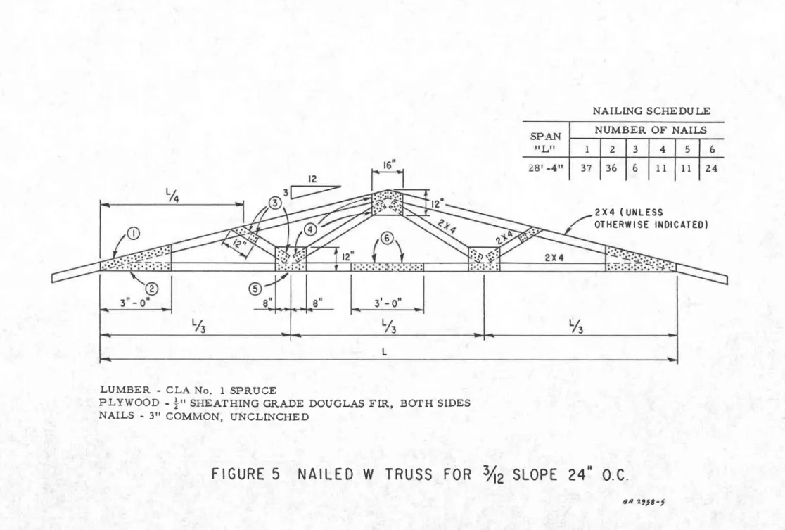
d e s i g n s d e t e r r n i n e d o n t h i s b a s i s a r e s h o w n i n F i g u r e s 3 t o 5 , i n c l u s i v e . In later tests the number of nails was reduced to two thirds and one half the original nailing to deterrnine the effect of nail reduction on over-all strength and stiffness of the assembly.
R e s u l t s o f T e s t s
A s u m m a r y o f r e s u l t s o f s h o r t t e r m t e s t s o n c o n v e n t i o n a l c o n s t r u c t i o n i s s h o w n i n T a b l e I . T a b l e I I s u m m a r i z e s t h e r e s u l t s o f
t h e f l r s t s e r i e s o f s h o r t t e r m t e s t s o n t r u s s e s , T a b l e I I I , t h e l a t e r s e r l e s . A s m e n t l o n e d e a r l l e r , t h e t e e t p r o c e d u r e l n t h i s l a t e r s e r i e s h a d b e e n s l i g h t l y r e v i s e d . T h e t e s t r e s u l t e a r e s h o w n o n t h e b a s i s o f
I6-in. spacings for conventional construction and 24-in. spacings f o r t r u s s e s . E x c e p t a s i n d i c a t e d i n T a b l e I I t h e r e s u l t s i n T a b l e s I t o I I I a r e b a s e d o n a n a v e r a g e o f t h r e e t e s t s ( s i x r o o f f r a r n e s ) i n e a c h c a s e .
The curves in Figure 5 show the effect of roof slope on the deflection characteristic of trusses with similar spans and main m e m b e r s i z e s .
Figure 7 shows the effect of span length on trusses having equal roof slopes and tnain mernber sizes.
Figure 8 illustrates the effect of increasing the rnain rnernber s i z e s o n t h e d e f l e c t i o n o f t r u s s e s .
The variation in truss stiffness caused by variations in nailing a r e i l l u s t r a t e d b y t h e c u r v e s i n F i g u r e 9 .
Figure I0 shows a typical over-all deflection pattern of a truss sirnply supported at each end, the deflection pattern of the same truds having a partition located at various positions beneath the lower chord. The loads measured at each partition locatlon are also shown in Figure 10.
T h e r e s u l t s o f t e s t s s h o w n i n F i g u r e s 6 t o l I i n c l u s i v e a r e b a s e d o n s h o r t t e r r n t e s t s o n s p r u c e t r u s s e s . T h e t e s t r e s u l t s i l l u s t r a t e d i n F i g u r e s 5 , 7 a n d 9 a r e b a s e d o n t h e a v e r a g e o f t h r e e t e s t s ( 6 t r u s s e s ) i n a l l c a s e s . T h o s e s h o w n i n F i g u r e s B , l 0 a n d I I a r e b a s e d o n a s i n g l e t e s t ( t w o t r u s s e s ) , e x c e p t a s o t h e r w i s e n o t e d i n F i g u r e 8 .
The results of long terrn tests on conventional joist and rafter construction are shown in Table IV and are based on single tests of the type of constructibn shown in Figure l. The surnmary of long term test r e s u l t s o n t r u s s e s i s s h o w n i n T a b l e V , a n d i s b a s e d o n s i n g l e t e s t s (two trusses) of the design shown in Figure 3.
DISCUSSION OF TEST RESULTS
Conventional C onstruction
Conventional roof fr arnes wide range of failure loads frorn l8
t h a t w e r e t e s t e d s h o w e d a n e x t r e m e l y t o l Z 5 l b / s q f t , d e p e n d i n g o n t h e h e e l
6
-joint details, size of rafter and fixation of the end supports*:When t e s t e d o n r o l l e r s u p p o r t s , t h e y w e r e l Z p e r c e n t s t r o n g e r w i t h 2 x 6 rafters and 59 per cent stronger with Z x 8 rafters than with 2 x 4 r a f t e r s ( F i g u r e l ) , e v e n t h o u g h f a i l u r e s o c c u r r e d f o r t h e m o s t p a r t a t t h e s a m e l o c a t i o n ( h e e l j o i n t o r c e n t r e j o i s t s p l i c e s ) . I n t h e c a s e o f the construction shown in Figure 2, assernblies rnade with 2 x 8 rafters were over Zt times as strong as those with 2 x 4 rafters, even though the nailing was the same; all failures occurred at the heel joints. Thle
increase in strength with rafter size is probably due in part to the fact that the stiffer the rafter, the less the collar beam will contribute to the outward thrust of the rafter.
In practice, the most comrr-ron type of construction is that shown in Figure I with 2 x 6 rafters. This type had failure loads of between 62 and I I3 fb/sq ft depending on whether the supports were on rollers or were fixed so that they could not rrrove outwards. Norrnally, the exterior walls of a house would provide little resistance to rafter spread and the failure load in practice would probably be closer to a
value of.62 fb/sq ft. It may be of interest to note that nailing requirements for roof framing in Canada have been upgraded sornewhat since these
t e s t s w e r e c a r r i e d o u t , s o t h a t p r e s e n t r e q u i r e m e n t s a s o u t l i n e d i n the I963 Housing Standards should ensure a minirnum failure load of about 70 Lb/sqft for conventional framing built in snow load areae of 5 0 f b / s q f t o r m o r e . T h e s e f a i l u r e l o a d s , o f c o u r s e , r e f e r t o s h o r t terrn loading tests; for longer duration loading the failure load mlght be c o n s i d e r a b l y l o w e r .
P e r f o r m a n c e C r i t e r i a
Conventional framing, constructed in accordance with
requirernents in the 1953 edition of the National Building Code, has been used for a number of years with few if any reported failures. It seems reasonable, therefore, to use past e>cperience with conventional construction in establishing an'acceptable standard of performance for truss
c o n s t r u c t i o n . I t a l s o s e e m s r e a s o n a b l e t o r e l a t e t h e p e r f o r m a n c e s t a n d a r d t o t h e d e s i g n s n o w l o a d f o r t h e a r e a i n w h i c h t h e t r u s s i s t o b e u s e d ,
so that a uniform factor of safety can be established across the country. T h e p e r f o r m a n c e c r i t e r i a f o r t r u s s e s i n t h e 1 9 5 3 e d i t i o n o f t h e H o u s i n g
Standards is a reasonable atternpt to achieve these goals. The criteria require that a truss be able to withstand at least twice the design roof load plus the ceiling load for 24hr, and that it rnust not deflect more than
I / 3 6 0 o f t h e s p a n u n d e r t h e f u l l d e s i g n l o a d a f t e r I h r . T h e s e c r i t e r i a
ensure that truss construction will be at least as strong as good conventional r o o f f r a m i n g .
T r u s s e s
T h e t r u s s r e s u l t s r e p o r t e d i n T a b l e I I I a r e b a s e d o n t e s t s c o n d u c t e d i n t h e l i g h t o f t h e s e p e r f o r m a n c e c r i t e r i a , w h e r e a s the t r u s s t e s t s r e p o r t e d i n T a b l e I I w e r e c o n d u c t e d b e f o r e t h e s e c r i t e r i a h a d b e e n d e v e l o p e d . B e c a u s e o f t h e l a r g e n u m b e r o f t e s t s o n trusses, however, there are sufficient data available on the factors affecting
s t r e n g t h a n d d e f l e c t i o n t o p e r m i t a s s e s s m e n t o f t h e t r u s s r e s u l t s i n T a b l e I I .
E f f e c t o f T r u s s S I o p e
The effect of roof slope on truss deflections is shown in
F i g u r e 5 , w h i c h i n d i c a t e s t h e a v e r a g e ' m i d - s p a n deflection f.or 28-ft span s P r u c e t r u s s e s w i t h s i m i l a r s i z e m a i n r n e r n b e r s and nailing calculated for the same design load. At a deflection of. l/360 of the span, the roof l o a d p l u s t h e c e i l i n g l o a d ( 1 0 p s f ) w a s 48 psf for a truss slope of. lf tz, 7 I p s f f o r a s l o p e o f . a / L Z a n d 96 psf for a slope of.5/tZ.
U n d e r a r o o f l o a d o f 5 0 p s f , 3 / t Z s l o p e t r u s s e s d e f l e c t e d 0 . 9 5 i n . , 4 / 1 2 s l o p e t r u s s e s a b o u t 0 . 6 5 i n . ,
" r r d 5 / t Z s t o p e t r u s s e s 0 . 4 5 i n . , even though the load per nail was approximately the same in a l l c a s e s . T h i s c a n b e e x p l a i n e d b y t h e f a c t that the deflection caused by a given amount of nail slip at the joints and the deflection caused by a x i a l s t r a i n s i n t h e r n e m b e r s i s i n c r e a s e d as the slope is decreased.
T h e a v e r a g e f a i l u r e l o a d f o r t h e s e s l o p e o f . 3 / t 2 , l 3 l a n d I 3 5 p s f f o r a s l o p e o f o f 5 / t Z . T h i s r n e a n s t h a t + / t Z s l o p e t r u s s e s s t r o n g e r a n d 5 / L 2 s l o p e t r u s s e s a b o u t 35 per s l o p e t r u s s e s . t r u s s e s w a s 1 0 7 p s f f o r a + f t Z , a n d 1 4 5 p s f . f o r a s l o p e w e r e a b o u t Z 5 p e r c e n t cent stronger fnan 3/lZ
E f f e c t o f T r u s s S p a n
F i g u r e 7 s h o w s t h e e f f e c t o f t r u s s s p a n o n truss deflectlon. A I I t r u s s e s i n t h i s c a s e a r e s p r u c e w i t h a slope of. a/ IZ and nailing c a l c u l a t e d t o s u p p o r t t h e s a r n e d e s i g n loads. A roof load of ?l psf was r e q u i r e d t o c a u s e a d e f l e c t i o n e q u a l to l/360 of the span for the zg-ft t r u s s ; l o a d s o f . 8 4 p s f f o r t h e z 6 - f t span, and g7 psf for t]ne z4-ft span w e r e r e q u i r e d t o p r o d u c e t h e s a m e deflection ratio. That is, at a d e f l e c t i o n o f . r / 3 6 0 o f t h e s p a n the 26-ft trusses supported lg per cent r n o r e r o o f l o a d a n d t h e Z L - f . t t r u s s e s about 23 per cent rnore roof load than t h e Z t J - f t s p a n trusses. T h e s e v a l u e s i n d i c a t e a t r e n d t o w a r d s s t i f f e r
- 8 -
P*,
The failure load for Z 6 - f t t r u s s e s i t w a s f 3 0 l b / s q
T r u s s M e r n b e r S i z e s
Z B - f t t r u s s e s w a s l 3 I L b / s q f t ; f o r
f t ; a n d f o r 2 4 - f t t r u s s e e i t w a s 1 6 5 l b / s q f t .
The deflection curves in Figure B,show the relative effect of m e m b e r s i z e s o n d e f l e c t i o n c h a r a c t e r i e t i c s a n d s t r e n g t h . T h e s e c u r v e g
show the mid-span deflection of. 28-ft span, +/tZ'sLope spruce trusses with identical nailing. Although these curves are in rnost instances based
o n a s i n g l e t e s t ( t w o t r u s s e s ) t h e r e s u l t s i n d i c a t e a t r e n d , s h o w i n g a n increase in stiffness by substituting 2 x 6 chord rnembers for 2 x 4 m e m b e r s . T h e r o o f l o a d n e c e s s a r y ! o c a u s e a d e f l e c t i o n o f l / 3 6 0 of the span, for example, is about 68 psf if. Z x 4 rnernbers are used t h r o u g h o u t , 7 9 p s f i f . Z x 5 t o p c h o r d s a r e u s e d , 8 l p s f i f . 2 x 6 b o t t o r n c h o r d s a r e u s e d , a n d 1 0 2 p s f i f . 2 x 5 t o p a n d b o t t o r n c h o r d s a r e u s e d . Bottom chords of Z x 6 seem to contribute more in reducing deflections than 2 x 6 top chords at roof loads below 90 psf, but the revef se seerns t r u e a t l o a d s a b o v e 9 0 p s f . T h e f a i l u r e l o a d w a s 1 3 5 p s f f o r t r u s s e s r n a d e e n t i r e l y o f 2 x 4 t e , a n d i n c r e a s e d o n l y t o I 4 0 p s f i f . 2 x 6 b o t t o r n c h o r d s w e r e u s e d . W h e n 2 x 6 t o p c h o r d s w e r e u s e d , h o w e v e r , t h e f a i l u r e l o a d w a s i n c r e a s e d t o l 7 l p s f , a n d i f Z x 6 c h o r d s w e r e u s e d b o t h t o p a n d b o t t o m t h e f a i l u r e l o a d w a s i n c r e a s e d o n l y t o 1 7 6 L b / s q t t . T h i s p a t t e r n o f i n c r e a s e i s understandable when one considers that the failures in trusses with 2 x 4 top chords occurred when the top chord broke in bending. When
2 x 6 t o p c h o r d s w e r e u s e d f a i l u r e o c c u r r e d i n o n e i n s t a n c e a t t h e c e n t r e splice in a mernber containing dry rot, and in the other case by lateral instability of the structure.
The sarne pattern of behaviour may be seen in the results l i s t e d i n T a b l e I I I , w h e r e t h e f a i l u r e l o a d f o r Z 8 - f t s p a n 3 / t Z s l o p e t r u s s e s w a s i n c r e a s e d f r o r n 1 0 7 t o 1 8 4 p s f i f . 2 x 6 t o p c h o r d s w e r e
substituted for 2 x 4ts, even though the nailing was the sarne. This change a l s o r e d u c e d t h e d e f l e c t i o n f r o m 0 . 9 5 t o 0 . ? 5 i n . ( a b o u t 2 l p e r c e n t
l e s s ) a t a 5 0 p s f r o o f l o a d .
Nailing
A s r n a y b e s e e n i n F i g u r e 9 , d e f l e c t i o n l s c o n s i d e r a b l y i n f l u e n c e d by the nailing. Figure 9 is based on tests of.}B-ft span +f tZ slope spruce trusses. At a deflection equal to l/360 of the span the roof load was
7 l p s f w h e n f u l l n a i l i n g w a s u s e d , 5 5 p s f w h e n i t w a s reduced by one third, and 44 psf when it was reduced by one half. In other words, when
t h e n a i l i n g w a s r e d u c e d 3 3 p e r c e n t , a d e f l e c t i o n o f l / 3 6 0 o f t h e s p a n w a s a 50 per cent reduction the roof load b y o n l y 3 8 p e r c e n t .
the roof load carrying capacity at reduced by only 23 per cent; and at c a u s i n g t h i s d e f l e c t i o n w a s r e d u c e d
The failure load for these trusses with full nailing was I 3 l l b / s q f t ( T a b l e I I ) ; a t t w o - t h i r d s n a i l i n g i t w a s 1 0 5 p s f ( T a b l e I I I ) , or about 80 per cent of value for full nailing; at one-hatf nailing it was 8 7 l b / s q f t ( T a b l e I I I ) , o r a b o u t 5 6 p e r c e n t o f s t r e n g t h w i t h f u l l nailing. It is of interest to note that the trusses did not fail at the joints, even at one-half nailing; failure was invariably structural - in the chord m e m b e r s . I t m u s t b e a s s u r n e d , t h e r e f o r e , t h a t t h e r e d u c t i o n i n l o a d -c a r r y i n g -c a p a -c i t y w a s -c a u s e d b y a n i n -c r e a s e i n total stresses resulting f r o r n t h e g r e a t e r d i s t o r t i o n o f t h e t r u s s with reduced nailing.
Duration of Loading
T h e d e f l e c t i o n o f t r u s s e s u n d e r a r e l a t i v e l y l o n g t e r m l o a d i n g m a y b e s e e n i n T a b l e V f o r v a r i o u s r o o f l o a d s . The percentage increase in deflection after a given tirne interval was fairly constant and relatively independent of the applied load. The average increase in deflection after one hour of loading was 6 per cent; after one day, 26 per cent; after one week, 55 per cent; and after one rnonth, 9T per cent. During this s e r i e s o f t e s t s t r u s s e s s u b j e c t e d t o an 80 psf roof load collapsed due to l a t e r a l i n s t a b l l i t y a f t e r I Z d a y s , and those subjected to 60 psf roof load c o l l a p s e d a f t e r Z Z d a y s f o r t h e sarne reason. These failures were not c o n s i d e r e d t r u e f a i l u r e s , h o w e v e r , because the sarne trusses installed i n a h o u s e r o o f w o u l d r e c e i v e c o n s i d e r a b l y rnore lateral restraint than w a s Provided in this test for only one pair of trusses sheathed with I x 6 board sheathlng. The rernaining trusses continued to show deflection recovery for one month after the loads had been rernoved.
Location of Partitions
It has been cofirr''on practice among sorrre authorities to
c o n s i d e r p a r t i t i o n s l o c a t e d b e n e a t h trusses as non-load bearing. Atthough to the authorrs knowledge this has not caused any difficulties, tests
i n d i c a t e t h a t t r u s s e s d e f l e c t i n g under load can exert considerable force o n a p a r t i t i o n r e s t r a i n i n g t h i s deflection (Figure l0). At a 40 psf roof l o a d a n d l 0 p s f c e i l i n g l o a d , f o r example, this load has been measured at 44o lb/truss if the partition is located at the centre of the span, 1800 lb/truss if the partition is located at the junction of the diagonal members, and 240 lb/truss if it is located mid-way between the end panel p o i n t s . T h e s e v a l u e s a r e f o r a ? 6 - f t span, 4/tz srope spruce truss of the tlpe shown in Figure 4.
1 0
-I f t h e p a r t i t i o n y i e l d s , t h e s e l o a d s w i l l , o f c o u r s e ' b e reduced, but the amount of yielding to eliminate load should equal the t r u s s d e f l e c t i o n a t t h e l o c a t i o n o f t h e p a r t i t i o n w h e n t h e t r u s s i s s i m p l y s u p p o r t e d a t t h e e n d s o n l y . T h e r e i s a p o s s i b i l i t y , t h e r e f o r e , t h a t i f o p e n i n g s i n p a r t i t i o n s a r e f r a r n e d a s n o n - l o a d b e a r i n g s o l r r e d a r n a g e t o t h e w a l l f i n i s h m a y r e s u l t i f t r u s s e s a r e s u b j e c t e d t o s u b s t a n t i a l s n o w l o a d s . T h e r e i s n o q u e s t i o n o f s t r u c t u r a l c o l l a p s e , h o w e v e r , b e c a u s e t h e l o a d i s r e d u c e d a s t h e p a r t i t i o n y i e l d s .
Cant il ever in g of T rus s e s
T h e c a n t i l e v e r i n g o f r o o f t r u s s e s ( o r i g i n a l l y d e s i g n e d t o b e e n d s u p p o r t e d ) i n s u c h a w a y t h a t t h e s u p p o r t o n t h e c a n t i l e v e r e d e n d l i e s b e t w e e n t w o e n d p a n e l p o i n t s c a n l o w e r t h e u l t i m a t e s t r e n g t h o f a t r u s s . T h i s c a n t i l e v e r i n g r n a y a l s o c a u s e a r e v e r s a l o f s t r e s s i n t h e w e b m e m b e r s o n t h e c a n t i l e v e r e d s i d e a s w e l l a s t h e c a n t i l e v e r e d p o r t i o n s o f t h e c h o r d r n e r n b e r s . F u r t h e r w o r k s e e m s t o b e r e q u i r e d i n d e v e l o p i n g a s t a n d a r d d e t a i l f o r c a n t i l e v e r i n g t r u s s e s o r i g i n a l l y d e s i g n e d t o b e e n d s u p p o r t e d . T h e r n e t h o d u s e d h e r e , w h e r e b y t h e c h o r d r n e r n b e r s o n t h e c a n t i l e v e r e d e n d w e r e i n c r e a s e d f r o m 2 x 4 t o Z x 6 a n d a v e r t i c a l s t r u t w e d g e d b e t w e e n t o p a n d b o t t o r n c h o r d s , w a s n o t a d e q u a t e t o develop strength equal to that of the end supported trusses with sirnilar n a i l i n g . F i g u r e I I s h o w s t h e r e s u l t s o f t h r e e t e s t s o n c a n t i l e v e r e d t r u s s e s i n w h i c h t h e s u p p o r t o n t h e c a n t i l e v e r e d e n d w a s l o c a t e d r n i d -w a y b e t -w e e n p a n e l p o i n t s a n d a Z x 4 s t r u t -w a s -w e d g e d b e t -w e e n t h e t o p a n d b o t t o r n c h o r d s a t t h e s u p p o r t . I n F i g u r e l l ( a ) t h e t r u s s e s w e r e o f t h e sarne t1rye as those shown in Figure 3, except that the top chord rnernbers o n t h e c a n t i l e v e r e d s i d e w e r e Z x 6 a n d t h e n a i l i n g w a s r e d u c e d t o Z / 3 , t h e n a i l i n g s h o w n i n F i g u r e 3 . T h e l o n g d i a g o n a l ( l i n . t h i c k ) b e g a n t o b u c k l e i n c o r n p r e s s i o n a t f a i r l y l o w l o a d i n g a n d f i n a l l y b r o k e b e f o r e a t o t a l r o o f l o a d o f 8 0 p s f h a d b e e n r e a c h e d , a t a b o u t t h e s a r n e t i r n e a s t h e t o p a n d b o t t o m c h o r d s b r o k e a t t h e c a n t i l e v e r i n g s u p p o r t . A t r u s s w i t h sirnilar nailing using Z x 4 top chords and supported at the ends would h a v e a f a i l u r e l o a d o f a p p r o x i m a t e l y 1 0 5 l b / s q f t ( T a b l e I I I ) .
T r u s s e s i n F i g u r e 1 l ( b ) a n d ( c ) w e r e s i r n i l a r t o t h e d e s i g n i n Flgure 4, except that Z x 6 top and bottom chord rnernbers were used on t h e c a n t i l e v e r e d e n d . T h e s e t r u s s e s h a d f a i l u r e l o a d s o f 8 0 a n d 1 0 0 I b / s q and failure occurred on the cantilevered end with the breaking of the top and bottorn chords in bending at the support. A sirnilar truss with 2 x 4 m e m b e r s t h r o u g h o u t s h o u l d h a v e a f a i l u r e l o a d o f 1 3 5 p s f w h e n s u p p o r t e d a t t h e e n d s ( T a b l e I I ) .
Application of Results
This test prograrn has shown that lf the design load per nail a n d t h e m e r n b e r s i z e s a r e c o n s t a n t t h e r e s u l t s o f t e s t s o n trusses of a given span and roof slope rrray be conservatively applied to shorter s P a n s a n d s t e e p e r s l o p e s w i t h o u t t h e n e c e s s i t y f o r f u r t h e r tests to d e v e l o p t r u s s d e s i g n s o f a t I e a s t e q u a l p e r f o r m a n c e . T h e n u m b e r o f n a i l s , a l s o , c a n b e s a f e l y r e d u c e d l n proportion-to the roof 1oad, or m o r e c o n s e r v a t i v e l y s t i l l , i n p r o p o r t i o n t o the total load (roof plus c e i l i n g ) , s o t h a t i f a g i v e n d e s i g n i s p r o o f tested for adequacy
in a given snow load area, the nailing may safely be reduced in proportion t o t h e t o t a l l o a d t o d e v e l o p d e s i g n s f o r trusses for areas with lower
s n o w l o a d s .
A s m e n t i o n e d p r e v i o u s l y , t h e r e s u l t s o f t h e t e s t s in Table II a r e f o r s h o r t t e r m t e s t s o n l y a n d w e r e d e t e r r n i n e d before accepted p e r f o r m a n c e c r i t e r i a h a d b e e n d e v e l o p e d . However, on the basis of t h e t e s t r e s u l t s s h o w n i n T a b l e s I I I and V, one rrlay attempt to assess t h e p e r f o r r r r a n c e o f t h e t r u s s e s i n T a b l e II in relation to these performance c r i t e r i a .
The precise relationship between the rnaxirnurn load that c a n b e c a r r i e d b y a t r u s s o v e r a z4-howr period as compared to the short term failure load is difficult to establish without extensive testing. s o m e u s e c a n , h o w e v e r , b e m a d e o f the data in Table III, s h o w i n g t h e r n a x i m u m p r o o f l o a d c a r r i e d b y the trusses, and the corresponding fallirre l o a d s w h e n t h e t r u s s e s w e r e t e s t e d to destruction. T l n e } 4 - h o u r p r o o f I o a d s s h o w n i n T a b l e I I I are not necessarily the largest Z4-hour load that could have been carried, however, since tine z4-hour proof loads w e r e a p p l i e d o n l y i n 2 0 p s f i n c r e m e n t s .
I n e x a m i n i n g t h e r e s u l t s o f T a b l e I I I , i t c a n b e s e e n t h a t the ratio of the Z4-hour proof load to the short terrn failure load was 0.76 f.or zB-f.t span 4/rz slope trusses with z/l tne nailing shown in Figure 3. In applying this ratio to the measured failure loads shown in Table II to predict the maximurn z4-hour proof loading that can be carried, the results should be on the conservative side. By rnultiplying this ratio by the failure loads in Table I I, it can be shown that all but t w o t r u s s e s w o u l d s u p p o r t a 24-hour proof loading of 100 psf; and that of these two the weakest truss should be able to withstand a Z4-hour p r o o f l o a d i n g o f 9? psf. A 9? psf proof load should be acceptable for s n o w l o a d a r e a s o f 4 8 . 5 L b / s q f t . c o n s i d e r i n g t h a t t h e 0 . 7 6 f . a c t o r r n a y be slightly low (in view of the 20 psf incrernent of proof loading) it would s e e m r e a s o n a b l e f o r a l l p r a c t i c a l purposes to consider all trusses in T a b l e I I a s m e e t i n g t h e perforrnance requirement of supporti4g twice the d e s i g n s n o w l o a d o f 5 0 p s f f . o r 24 hours.
I ' - r t ?
-With regard to the requirements for lirniting deflection, it may be seen from Table V that an increase in deflection after one hour of loading should not be more than about 6 per cent. If this increase in d e f l e c t i o n i s a p p l i e d t o t h e d e f l e c t i o n s s h o w n i n T a b l e I I f o r 5 0 p s f r o o f loads, the deflections would still be well within the limit of. l/360 of the
span. It would appear reasonable to conclude therefore that the trusses i n T a b l e I I m u s t r n e e t t h e a c c e p t e d p e r f o r m a n c e c r i t e r i a f o r t r u s s e s f o r a 5 0 p s f s n o w l o a d . O n t h e b a s i s o f t h e s e c o n s i d e r a t i o n s t h r e e n a i l i n g s c h e d u l e s h a v e b e e n p r e p a r e d t o p r o v i d e t r u s s d e s i g n s t o c o v e r a r a n g e o f s p a n s , s l o p e s a n d s n o w l o a d s t o s a t i s f y t h e p e r f o r m a n c e r e q u i r e m e n t s e e t a b l i s h e d i n t h e 1 9 6 3 H o u s i n g S t a n d a r d s . T a b t e V I l s a n a l l i n g s c h e d u l e f ^ o r 4 f 1 2 a n d 5 / I 2 s l o p e s p r u c e t r u s s e s w i t h s p a n s o f f r o m 1 6 t o 2 8 f t a n d s n o w Ioads of 30, 40 and 50 psf for the type of truss shown in Flgure 3,
Table VII Is slmllar except that lt applies to the type of truss shown ln Figure 4. Table VIII is the nailing schedule f.or 3/12 slope spruce trusses of the t1rye shown in Flgure 5. In thls case the spans also range frorn 16 to ZB ft and nalling is deterrnined for 30, 40 and 50 psf s n o w l o a d s .
C o n c l u s i o n s
l. Conventional constructions butlt prior to the introduction
o f t h e l 9 6 Z a n d I 9 6 3 H o u s i n g S t a n d a r d s s h o w a w i d e r a n g e o f l o a d c a r r y i n g capacities, sorne of which are as low as l8 psf under a short terrn loading.
z .
T h e c r i t e r i a o f a c c e p t a b l e p e r f o r m a n c e s t a t e strusses must withstand twice the design snow Load fot 24 not deflect rnore than l/360 of the span under design load It provides for roofs that are considerably stronger than f r a m e d r o o f s .
that roof
hours and must after one hour. most conventionally
3 . T h e s t i f f n e s s o f t r u s s e s w i t h m e r n b e r s o f s i r n i l a r s i z e a n d n a i l e d j o i n t s d e s i g n e d f o r t h e s a r n e l o a d i s i n c r e a s e d a s t h e s l o p e i s i n c r e a s e d o r a s t h e s p a n i s d e c r e a s e d .
4. Increasing the rnember sizes frorn 2 x 4 to Z x 6 in the top or b o t t o r n c h o r d s i n c r e a s e s t h e s t i f f n e s s a n d s t r e n g t h o f t r u s s e s . I n c r e a s e l n s t r e n g t h i s m o s t r n a r k e d w h e n t h e t o p c h o r d r n e m b e r s a r e i n c r e a s e d i n s i z e .
5 . T r u s s s t i f f n e s s i s d e c r e a s e d a s t h e n a i l i n g l s d e c r e a s e d . I f t h e n u m b e r o f n a i l s i s r e d u c e d b y a c e r t a i n p e r c e n t a g e , t h e l o a d r e q u i r e d
t o c a u e e e q u a l d e f l e c t i o n w i l l b e d e c r e a s e d by a smaller percentage.
6 .
T r u s s s t r e n g t h i s d e p e n d e n t t o s o m e e x t e n t upon truss s t i f f n e s s . l f t r u s s e s o f s i m i l a r m e m b e r s i z e and geometry, but with j o i n t s d e s i g n e d for different loadings, are tested to failure and failure o c c u r s i n t h e m e m b e r s a n d n o t at the joints, the stiffer trusses will h a v e h i g h e r f a i l u r e l o a d s .7 . T h e p e r c e n t a g e i n c r e a s e i n t r u s s d e f l e c t i o n s over an extended p e r i o d o f t i m e s e e m s l a r g e l y unrelated to the magnitude of the load. F o r t r u s s e s m a d e w i t h 2 x 4 mernbers, the increase in deflection is about 6 per cent after one hour, 26 per cent after one day, 55 per cent after one week, and 9T pet cent after one month.
8. contrary to popular conception, partitions located beneath
t r u s s e s c a n b e s u b j e c t e d t o l o a d s in excess of those born by partitions l o c a t e d b e n e a t h f r a m e d roofs. 9 . so that it 1 0 . p r o g r a m r n e e t t h e a b o v e criteria s i n c e b e e n i n c o r p o r a t e d i n t o t h e r o o f s o f a d e q u a t e p e r f o r m a n c e in w e r e d e v e l o p e d . c a n t i l e v e r i n g o f t r u s s e s b e y o n d t h e i r d e s i g n e d e n d s u p p o r t i s l o c a t e d b e t w e e n p a n e l p o i n t s can seriously weaken thern.
T h e r o o f t r u s s d e s i g n s d e v e l o p e d on the basis of this test o f a c c e p t a b l e p e r f o r m a n c e ( w h i c h h a s H o u s i n g S t a n d a r d s ) a n d s h o u l d p r o v l d e t h o s e s n o w l o a d a r e a s f o r w h i c h t h e y
Acknowledgment
W o r k o n r o o f t r u s s e s u n d e r t a k e n by the Division of Building R e s e a r c h h a s b e e n d e v e l o p e d j o i n t l y with the Forest Products Research B r a n c h - T h e i r c o - o p e r a t i o n i n t h e s e studies is very rnuch appreciated.
Bibliography I .
z.
3 . 4 . 5 . N a t i o n a l B u i l d i n g C o d e , C a n a d a , 1953. N a t i o n a l B u i l d i n g C o d e , C a n a d a , 1960.H o u s i n g s t a n d a r d s , D i v i s i o n of Building Research, National R e s e a r c h C o u n c i l , J a n u a r y I 9 5 8 .
H o u s i n g S t a n d a r d s , C a n a d a , L963, Supplement No. 5, National B u i l d i n g C o d e .
c l i r n a t e i n f o r m a t i o n f o r B u i l d i n g Design in canada, 196I, supplernent No. I, to the National Building code, canada.
TABLE I
SUMMARY OF RESULTS OF SHORT TERM TESTS ON CONVENTIONAL CONSTRUCTIONS WITH SPRUCE JOISTS
AND RAFTERS SPACED t6 in. O. C. T y p e o f C o n s t r u c t i o n R a f t e r S i z e : -t r l . Collar T i e S i z e i n . T y p e o f E n d Supports >F Ultimate R o o f Load ( P s f ) S e e F i g u r e Z x 4 2 x 4 2 x 4 Z x 4 R o l l e r s Fixed 5 6 7 Z Z x 6 2 x 6 Z x 6 2 x 6 l x 5 I x 5 ? x 4 Z x 4 R o l l e r s Fixed R o l l e r s Fixed 6 3 I I 3
6 z
r 0 8
Z x 8 Z x B ? x 4 Z x 4 R o l l e r s F i x e d 8 9rz5
S e e Figur e 2 x 4 Z x 4 ? x 4 2 x 4 R o l l e r s F i x e d I 8 t 8 ? x 8 2 x B 2 x 4 2 x 4 R o l l e r s Fixed4 6
46
d ' I n a d d i t i o n to l0 psf ceiling loadON NAILED w TRUSSES SPACED 24 in. O. C. T y p e of T r u s s Span ft S l o p e U p p e r C h o r d S i z e i n . L o w e r C h o r d S i z e i n . L o w e r C h o r d D e f l e c t i o n R a t i o f o r 4 0 . x p S l l ( O O f J - o a c l P e r c e n t a g e o f R e c o v e r y a f t e r 4 0 p s f R o o f L o a d R e m o v e d L o w e r C h o r d Deflection R a t i o f o r 5 0 p s f R o o f L o a d { F a i l u r e L o a c l ' (psf) S p r u c e ( s e e F i g u r e 3 )
z 4
z 4
z 6
2 hz 8
z 8
z 8
5 / 4/ 4/ 4/ 4/z
?z
z
2z
z
2 x 4 2 x 4 Z x 4 2 x 4 2 x 4 Z x 4 Z x 5 Z x 4 Z x 4 Z x 4 Z x 4 Z x 4 Z x 4 Z x 4 L / 9 L o L / 8 z o L / B 7 o r /8oo | /890 L / 6 0 0 r / 6 9 0 6 9 7 8 6 9 t ) 7 Z 7 L 7 7 r / 7 4 0 t / 6 7 0r / 7 z o
r / 6 6 0 r / ? 4 0r /5oo
r / 5 7 0 1 6 3 l b 5 143 1 3 0 t 4 5 l 3 l t 4 2 Spruce ( s e e F i g u r e 4 )z 6
z 8
z 8
z 8
z 8
4 / rz
+ / rz
4 / rz
4 / r z
4 / r z
2 x 4 Z x 4 2 x 6 Z x 4 Z x 6 Z x 4 Z x 4 Z x 4 2 x 6 2 x 6t / 6 r o
r /6 L o
L /650r /8oo
t / Lo3o
7 L 7 0 7 3 7 9 7 9| /5oo
L / 5 r c
r / 5 5 0
r / 6 5 0
r /B4o
I Z ? r 3 5 I 7 I ' l ' * 140>i<v'< I ? 6r,.* D o u g l a s F i r ( s e e F i g u r e 4 ) ) Az 8
+ / tz
+ / tz
Z x 4Z x 4 Z x 4 Z x 4 | /.650r /590
6 67 4 r /,520r /470 I T 7r 3 6
, i . In addition to 10 psf ceiling load ' k ' l Based on one test onlv
T A B L E I I I
SHORT TERM TESTS ON TRUSSES TO DETERMINE ACCEPTABILITY FoR vARIous sNow LOAD AREAS. TRUSSES spAcED 24 i... o, c. T y p u of T r u s s Span Slope U p p e r C h o r d S i z e L o w e r C h o r d S i z e L o w e r c h o r d d e f l e c t i o n r a t i o s a f t e r I - h r l o a d i r r s M a x . r o o f l o a d s u s t a i n e d f o r 2 4 h r { ' ( p s f ) A v e r a g e f a i l u r e l o a o ( p s f ) 3 0 p s f Roof Loado' 4 0 p s f R o o f . L O a O 5 0 p s f Roof L o a d ' F 6 0 p s f R o o f Loadx S p r u c e ( s e e F i g u r e 5 )
z 8
z 8
3 / r z
3
/ r z
Z x 4 2 x 6 Z x 4 2 x 4 r /4 1 5 L /390 8 0 l z 0 1 0 7 1 8 4 S p r u c e ( s e e N o t e I b e l o w ) 2 84 / r z
Z x 4 2 x 4| /5rc
6 0 8 7 S p r u c e ( s e e N o t e 2 b e l o w )z 8
4 / L z 2 x 4 2 x 4 r /470 8 0 I 0 5Note I - T!us3€3 sirnilar to those in Figure 3 except that the nurnbe! of nails $?as teduc€d to 50 per cert of the nurhber shown in Figule 3
-\ Note 2 - Trusses similar to those ir Figure 3 except that th€ nurnber of nails was reduced to Z/3 of. tb,e
a \ nurnber shown ia figure 3
lz4-ft spAN, 5/LZ SLOPE, Z x 6 SFRUCE RAS.TERS A N D J O I S T S S P A C E D 16 in. O. C. (FICURE t))
TESTED ON ROLLER SUPPORTS L o a d i n g P h a s e A p p l i e d R o o f L o a d ( p s f )
Joist Splice Separation ( i n . )
P e a k D e f l e c t i o n s (in. )
Mid -span Rafter D e f l e c t i o n s , P erpendicular t o S l o p e ( i n . ) 5 Min. I H o u r I Dev I W e e k I Month - 5 Min. I Hour l Day t W e e k I Month 5 Min. I Hour I Day I W e e k I Month F i r s t a p p l i c a t i o n o f ' l o n g t e r r r r r o o f and ceiling load
z 0
4 0 0 . 0 3 ? 0 . i 0 g 0 . 0 3 9 0 . l i 5 0 . 0 5 0 0 . r 4 4 0 . 0 6 ? 0 . 2 3 3 1 0 9 384 0 . 0 .0 . rz
0 . 3 9 0 . 0 . l 3 4 3 0 . l 6 0 . 5 5 0 . 2 3 v . I I 0 . 3 5 r . 0 9 0 . 0 80 . z z
0 . 0 8 0 . 2 4 0 . n l 0 3 0 0 . 1 4 0 . 4 3 0 . 1 9 0 . 6 3 R o o f l o a d s a n d c e i l i n g l o a d s r e m o v e d 0 0 0 . 0 6 0 0 . 3 l g 0 . 0 5 9 0 . 3 1 6 0 . 0 5 7 o . 3 t z 0. 04rl 0 . 3 1 0 047 3 0 3 0 0o . z 0
0 . 8 2 0 . z o 0 . 8 1 0 . z 0 0 . 8 0 0 . 1 9 0 . 7 8 0 . l g u . { 6 0 . l 0 0 . 4 2 0 . l 0 0 . 4 0 0 . 0 9 0 . 3 9 0 . 0 9 0 . 3 8 0 . 0 8 0 . 3 5' i ' Structure originally loaded with Z0 psf roof load ' i ' : l < S t r u c t u r e o r i g i n a l l y l o a d e d w i t h 4 0 p s f r o o f l o a d
T A B L E V
SUMMARY OF LONG TERM TRUSS TESTS (26.ft SPAN, 4/12 SLOPE SPRUCE TRUSSES SPACED 24 in. O. C. OF DESIGN SHOWN
IN FIGURE 3 vrITH 2 x 4 TOP AND BOTTOM CHORDS)
L o a d i n g P h a s e
A , p p I i e d R o o f L o a d s
MID SPAN DEFLECTIONS OF LOWER CHORDS
5 M i n u t e s I H o u r I D a v I W e e k M o n t h I n . I n . P e r c e n t a g e I n c r e a s e o v e r 5 - m i n D e f l e c t i o n s r n _ P e r c e n t a g e I n c r e a s e o v e r 5 - m i n D e f l e c t i o n s I n . P e r c e n t a g e I n c r e a s e o v e r 5 - m i n D e f l e c t i o n s P e r c e n t a g e I n c r e a s e o v e r 5 - m i n D e f l e c t i o n s F i r s t a p p l i c a t i o n o f I o n g t e r m r o o f l o a d s a n d c e i l i n g l o a d s a i 40 O U 8 0 0 . 3 0 0 . 5 5 0 , 7 9 5 I . T Z 0 . 3 1 5 0 . 5 8 0 , 8 4 I . Z l 5 5 6 8 0 . 3 8 5 0 . 6 8 0 . 9 8 5 r . 4 2 z 8 z 4 2 4 z 7 0 . 4 8 0 . 8 3 l . l 9 t - I ) ) 6 0 l l ) U ) t 0 . 5 0 r . 0 6 1 0 0 o ? R o o f l o a d s a n d c e i l i n g l o a d s r e m o v e d I n . P e r c e n t a g e R e c o v e r v P e r c e n t a g e R e c o v e r v P e r c e n t a g e R e c o v e r v I n . P e r c e n t a g e R e c o v e r v Tn P e r c e n t a g e R e c o v e r y J J f 5 U 5 4 4 5 Z 0 . 3 2 0 . 4 9 4 7 5 4 n 2 a ( o. 445 5 I f 6 v . a o ) 0 , 3 9 5 6 o 5 5 8 o a S e c o n d a p p l i c a t i o n o f l o n g t e r m r o o f l o a d s a n d c e i l i n g l o a d s z 0 4 0 I n . P e r c e n t a g e o f O r i g i o a l I - m o D e f l e c t i o n s I n . P e r c e n t a g e o f Or i ginal I - m o D e f l e c t i o n s I n P e r c e n t a g e o f O r i g i n a l I - m o D e f l e c t i o n s I n . P e r c e n t a g e o f O r i g i n a l l - m o D e f l e c t i o n s I n . P e r c e n t a g e o f O r i g i n a l I - m o D e f l e c t i o n s . 5 2 5 8 8 6 ) o . 5 4 5 0 . 9 1 5 8 6 n 5 5 5 9 4 a ? 8 9 0 . 5 8 r , 0 0 9 7 9 4 * T r u s s e s o r i g i n a l l y l o a d e d w i t h 2 0 p s f r o o f l o a d / t * T r u s s e s o r i g i n a l l y I o a d e d w i t h 4 0 p s f r o o f l o a d * t r * S t r u c t u r e c o l l a p s e d d u e t o l a t e r a l i n s t a b i l i t y a f t e t 2 2 d a y s * * * * S t r u c t u r e c o l l a p s e d d i . r e to l a t e r a l i n s t a b i l i t y a f t e r l 2 d a y s .
DII.I.ERENT SNOW LOAD AREAS. TRUSS DESIGNS IN FIGURE 3 S P A C E D 2 4 i n . O . C . S P R U C E - 2 x 4 T O P A N D B O T T O M C H O R D S Snow
l o a d a r e a
Slope Span Joint Ioeation
( s e e F i g u r e 3 )
l n .
o
3 -in. nails 3 -in. nails
@
2* -in. nailso
2* -in. nails@
@
3 -in. nails 3 0 p s f4 / r z
l 6 I 8 z 0z z
z 4
z 6
z 8
4 4 4 4 4 4 4 9 l 0 I I TZ l 3 t 4 I 5 8 9 l 0 I I T Z l 3 l 4 5 5 5 . 5 5 t 5 5 6 7 7 8 9 9 5 6 I 7 8 o 9 3 0 p s f5 / r z
r 6
I 8 z 0z z
z 4
z 6
z 8
4 4 4 4 4 4 4 7 8 9 I O t 0 I I T Z 7 7 I 9 I O t 0 l l ) t 5 5 5 f ) 6 6 T 8 8 9 f 5 6 6 ( t 8 4 0 p s f 4 / t z 1 6 l 8zo
zz
z 4 z 6 z 8 4 4 4 4 4 ^ t 4 LZ t 3 1 5 l 5 I ? l 9z 0
I I L Z l 3 l 4 l 6 t 7 l 8 f 5 t 5 t ) 5 7 8 9 I O l l l l LZ I 8 9 t 0 I I 1 l t 2 4 0 p s f 5 / L z 1 6 l 8z o
z z
z 4 z 6 z 8 4 4 4 4 4 4 4 t 0 I I I Z l 3 T 4 l 5 l 6 9 I O I It z
I 3 t 4 l 5 5 ) f f 5 5 7 I I 9 l 0 l t I Z 6 7 8 I 9 I O l 0 5 0 p s f4 / r z
l 6 l 8 z 0z z
z 4 2 6 Z B 4 4 4 4 ^ 4 4 L 7 I 9 Z I z 3 z 5 z 7 z 9 I 6 I Bzo
Z L z 3 z 5 z 7 5 f f 5 5 5 5 t lt z
I 3 I 4 l 6 t 7 l 8 l l I Z I 3 t 4 r 6 l 7 I 8 5 0 p s f5 / rz
r 6 l 8 z 0z z
z 4 z 6 Z B 4 4 4 4 4 i I A I T l 6 L 7 1 0z o
z z
z 4
l 3 t 4 I 6 t 7 l 9zo
z 2 5 5 5 5 5 5 5 l 0 I I I Z I 4 l 5 l 6 I ' 9 l 0 l l t z t 3 t 4 I 5N U M B E R O F 3-in.
DIFFERENT SNOW
S P A C E D 24 in. O. C.
T A B L E V I ]
NAILS REQUIRED AT VARIOUS JOINTS FOR
LOAD AREAS. TRUSS DESIGN IN T'IGURE 4
S P R U C E - Z x 4 T O P A N D B O T T O M C H O R D S Snow Ioad a r e a S l o p e Span J o i n t l o c a t i o n ( s e e F i e u r e 4 ) f+ I n . I
(z)
( 3 ) & \ (5) (6) 3 0 p s f4 / r z
l 6 l 8z 0
z z
z 4
z 6
z 8
4 4 4 4 4 4 4 q l 0 l lt z
l 3 t 4 l 5 8 9 l 0 l l I Z l 3 T 4 ) 7 ) 7 3 3 3 3 3 5 A 4 4 4 5 4 4 4 5 5 5 6 1 a 7 I 9 9 3 0 p s f 5 / L z T 6 l 8z o
z z
z 4
z 6
z 8
4 4 4 4 4 4 4 7 8 9 l 0 I O l l L Z I I 7 8 9 l 0 l 0 l lz
z
z
z
z
3 3 ) 3 3 3 3 4 ^ = 3 3 4 A T 4 5 5 5 5 6 6 I 7 8 4 0 p s f+ / t z
r 5
1 8 ? 0z z
z 4
z 6
z 8
4 4 + 4 4 4 4 T Z I 3 l i r I 6 I 7 l 9z o
l lt z
I 3 L 4 l 6 t 7 l 8 ) 3 3 3 4 4 4 4 4 4 5 5 6 6 4 5 f 6 6 I I 7 8 9 l 0 I I t l LZ 4 0 p s fs / r z
I 6 l 8 2 0z z
z 4
z 6
) 9 4 4 4 4 4 4 4 l 0 I I I Z l 3 L 4 l 5 l 6 9 i 0 t l I Z l 3 T 4 l 5 ) 3 3 3 3 4 4 3 4 4 4 4 5 5 4 4 f 5 6 6 6 6 8 8 9 l 0 l 0 5 0 p s f+ / rz
l 6 l 8z 0
z z
z 4
z 6
Z B 4 4 4 4 4 4 4 L I I 9 z l z 3 z 5 z 7 ) q l 6 I 8z 0
Z Iz 3
z 5
z 7
3 4 4 4 5 5 5 5 5 6 7 7 8 8 6 I a 8 9 l 0 l 0 l l l z I 3 L 4 l 6 I 7 l 8 5 0 p s f 5 / L z I O I Bz 0
z z
) A z 6 L 6 4 4 4 4 4 t 4r 6
L 7 t 9z o
z z
) 4 l 3 I +r 6
t 7 l q ) nz z
3 A I 4 4 5 5 4 5 5 6 6 7 5 6 7 I I 9 q 9 l 0 1 I 1 Z I 3 I A t a I 5DIFFERENT SNOW LOAD AREAS. TRUSS DESIGN IN FIGURE 5 SPACED 24 in. O. C. SPRUCE - 2 x 4 LOWER CHORDS
Snow I o a d a r e a
Span Joint location
( s e e F i g u r e 5 ) ft ln. I
z
3 4 5 6 3 0 p s f ( Z x 4 t o p c h o r d ) t 6 I Bz 0
z z
z 4
z 6
ZB 4 4 4 4 4 4 + I 7 I 9 2 Zz 3
z 6
ZB 3 0 I 7 I 9 Z T 2 3z 5
z 7
z 9
3 3 4 4 4 5 56
6
7 I8
9
9
6 6 7 7 8 9 9 I Ir 3
l 4 I 5 L 7 I 8 1 9 3 0 p s f ( 2 x 6 t o p c h o r d ) I 6 I Bz 0
z z
2 4z 6
z 8
4 4 4 4 4 1 4t z
L 4t 6
L 7 } Bz 0
Z L TZ t 3 I 5 T 7 I Bz 0
z l
J 3 3 3 3 4 4 4 4 5 5 6 7 7 4 4 5 5 6 t 7 89
I O I I TZ l 3 t 4 4 0 p s f ( ? x 4 t o p c h o r d ) I 6 I 8z 0
z z
z 4
z 6
ZB 4 4 4 4 A .*' 4 4 ZTz 4
z 7
z 9
3 Z 3 5 3 7z l
z 3
z 6
z 9
3 I 3 4 3 6 4 A .+ 5 5 5 6 6 7 7 89
I O
I I t l 7 7 B9
1 0
I I I tr 4
I 6 t 7r g
Z Lz 3
z 4
4 0 p s f ( 2 x 6 t o p c h o r d ) I 6 I Bz 0
z z
z 4
z 6
Z B 4 + + + 4 4 4 I 5 L 7 I 9 Z L 2 3z 5
z 7
I 5 t 7 1 9 Z Lz z
z 4
z 6
3 3 4 4 4 5 5 5 5 6 7 7 B B 5 5 6 7 7 B B I O I I I Z T 4 I 5 t 7 I 7 5 0 p s f ( Z x 6 t o p c h o r d ) I 6 I 8z o
z z
z 4
z 6
z 8
4 + 4 4 4 4 4 I Bz l
z 3
z 5
z 8
3 0 3 Z I Bz 0
2 2z 5
z 7
) Q 3 l 4 4 5 5 5 5 5 6 6 I I 9 I O l 0 6 6 7 8 9 I O I O L Z T 4 I 5 I 6 t 8z 0
z l
2 X 4
( U N L E S S O T H € R T Y I S E I N O I C A T E D I 2 X 4 . 2 X 6 0 R 2 X 8
LUMBER - CLA No. I SPRUCE NAILS - 3*" COMTTaON
3 NAILS JOIST TO RAFTER
3 NAII.S JOIST TO JOIST AT CENTER
2 TOE NAII.S EACH END OF EACH JOIST TO PLATE 3 TOE NAILS EACH RAFTER TO PLATE
3 NAIIS EACH END OF COLLAR TIE TO RAFTER
F I G U R E
I T Y P E I C O N V E N T I O N A L
C O N S T R U C T I O N
S P A C E D
1 6 , . O . C
1 t n 2 9 1 8 - t 2 4 ' - 4 " 2 4 ' - 4 " L U M B E R NATLS 3 3 z l l 3 z-CLA No. I SPRUCE
3+" Jolsr ro JoIST AT CENTER 3j" coLLAR TIE To RAFTER
4II HEADER TO END OF JOIST 4I' RAFTER PLATE TO JOTST 4II RAFTER PLATE TO HEADER 3 + ' , R A F T E R T o R A F T E R P L A T E 3j" JOrST TO JOTST PLATE (TOE
(TOE NAILED) NAILED)
F I G U R E
2 T Y P E
1 I C O N V E N T I O N A L
C O N S T R U C T I O N
S P A C E D
I 6 . ' O . C .
3 r ' n a i l s 3 r ' n a i l s 2 j l n a i l s Z j i l n a i l s 3 r t n a i l s 5 / L z z 4 t - 4 t l z 6 t - 4 t l z g t - 4 t l
z0
zz
2 4 T 9 7 6 z 2 5 5 5 l 5 l 6 't '7 l 3 L 4 I f 4 / L z z 4 t _ 4 t l z 6 t - 4 t l z g t - 4 t l 2 5 z 7 2 Q z 3 2 5 z ? 5 5 I 5 L ] l 8 I 6 t 1 l 8 2 X 4 S T R U T i -Z ,Za'rUrr-S' I X 6 T I E T O S T R U TLUN{BER - CLA No. I S,PRUCE
PLYWOOD - j" SHEATHING GRADE DOUGLAS FIR, BOTH SIDES NAILS - z*" AND 3'r COMMON - UNCLINCHED
2 E X C E E D E D Z O E X C E E D E D I 2 T O E I I A I L E A C H E T O O F 2 X 4 S T R U T W I T H 2 . 3 " I { A I L S 2 X 4 ( U I | L E S S H E R T I S E I I I O I C A T E D ) N O T E I
IZ;Fr-ers usED vrHEN No. oF NArrs FoR I AND
NOTE 2
I x 8 DIAGONALS USED WHEN NO. OF NAILS FOR 4
F IGURE 3
N A I L E D
W T R U S S
S P A C E D
2 4 " O . C .
S P R U C E T R U S S
LUMBER - CLA No. I SPRUCE OR CONST. GRADE DOUGLAS FIR P L Y W O O D - |" SHEATHING GRADE DOUGLAS FIR, BOTH SIDES N A I L S - 3 r ' C O M M O N , U N C L I N C H E D
DOUGLAS FIR TRUSS N A I L I N G S C H E D U L E
2 X 4 ( U N L E S S
O T H E R W I S E I N D I C A T E D ) NAILING SCI{EDULE
NUMBER OF NAII-S NUMBER OF NAILS
F I G U R E
4 NAILED
W T R U S S
S P A C E D
2 4 , , 0.C.
LUMBER - CLA No. I SPRUCE
PLYWOOD - j" SHtrAIHING GRADE DOUGLAS FIR, BOTH SIDES NAILS - 3I' COMMON, UNCLINCHED
2 X 4 ( U N L E S S
O T H E R W I S E I N D I C A T E O }
Ytz SLOPE
24" O.C.
iu{t
FIGURE
5 NAILED
W TRUSS
FOR
r 8 0 r 6 0
t
0 . 5 t . 0 t . 5 M I D - S P A N D E F L E C T I O N S , L O W E R C H O R D , I N . F I G U R E 6 D E F L E C T I O N C U R V E S F O R 2 8 ' S P A N , S P R U C E T R U S S E S W I T H 2 X 4 U P P E R A N D L O W E R C H O R D S W t T H N A I L I N G C A L C U L A T E D F O R S I M I L A R L O A D I N G S ,- 140 !) (L . t 2 0 o 3 t00 lr3 B o
G 3 6 0 f o-c 4 0 20 r 8 0 t 6 0 l . 1 4 0 U, a-- t 2 0 a9 roo
E8 o o
G 3 6 0 f o-o- 40 2 0 0 . 5 M I D - S P A N F I G U R E 7 D E F L E C T I O N C U R V E S F O R A N D L O W E R C H O R D S W I T H t . 0 t . 5 D E F L E C T I O N S , L O W E R C H O R D , I N . a / 1 2 S L } P E , S P R U C E T R U S S E S w l T H 2 X 4 U P P E R N A I L I N G C A L C U L A T E D F O R S l M I L A R L O A D I N G S I M I L A R T O D E S I G N S I M I L A R T O O E S I G N S I M I L A R T O D E S I G N I N F I G . 3 l N F l G . o a / t z SLOPE l N F l c . 5 f i / i -T R U S S D E S I G N A S P E R F I G 3 2 4 F l,- 160 an o-ci 3 t 2 0 J l! o
8 B o
ct lrl = t 4 0 2'X 6" TOP CHoRDS zn x 4" Borroli cHoRos 2-x 4" IoP CHORDS 2r x 6" B0TT0[, cHoR0s 2" X 6' ToP CHORDSzi'x
5' BorToM
cHoRDs
z"x c" ToP
cHoRDs
2" X 4' BOTTOM CHORDS ( O N E T E S T O N L Y ) ( O N E T E S T O N L Y ) ( O N E T E S T O N L Y ) ( A V G O F 3 T E S T S ) L E G E N Do
@
@
@
F I G U R E 8 L O A D V S D E F L E C T I O N C U R V E S 2 8 . S P A N , % z S L O P E , ( D E S I G N S I M I L A R T O F I G 4 ) M E M B E R S I Z E S B U T S I M I L A R N A I L I N G S P R U C E T R U S S E S F O R D I F F E R E N T An zrrt-t j/3.0 or senN cErLmG L O A O t . 2 0 r . 6 0 2 . 0 0 | 2 - 4 0 2 . 8 0 M I D - S P A N O E F L E C T I O N S , L O I Y E R C H O R D , I N .ra0
t50 E 140 v, o. . t 8 0 q {3 roo
tl8 a o
c3 B o
o.t 4 0
20 0 -'/'-\ r a r r - r i l G R E o u c E D 8Y lz j/sso spAN c E r L i l t G L O A DI
I( , C
0 . 5
t . o
t . 5
I
z . o
I r 0 - S P A N 0 E F I E C T t o t t s , L o W E R G H o R D . m . F I G U R E 9 O E F L E C T I O N C U R V E S F O R S P R U C E T R U S S E S W I T H V A R I A T I O N S I NN A f L f N G
z B ' s p A N ,
4 / z s L o p E
( F r c
3 l a x 4 u p p E R
A N D
L o w E R
c H o R D s
T R U S S D E F L E C T I O N S W I I H O U T IN I E R i l E O I A T E S U P P O R T S I I { T E R T E D I A T E S P A i I O F T H E R O O F L O A O 4 0 P S F 8 0 P S F R O O F L O A D 4 0 P S F 8 0 P S F R O O F L O A D 0 E r L E C T t 0 l l 99AL E a 0 . 0 0 " I - { o.60' I J t . o o ' OE FL ECT IOX S C A L E --l 0.oo' 1 o.so' J t . o o " T R U S S D E F T E C T I O I I S W I T H S U P P O R T L O C A T E D A T M I D L O W E R C H O R D L O A O O I { P A R T I T I O l I ( P E R T R U S S I 4 4 0 L B ? 5 0 L 8 L 0 a 0 0 1 ' t P A R T l T l 0 l { I P E R T R U S S I r 8 0 0 L 8 2 9 0 0 L B L O A O O N P A R T I T I O i I ( P E R T R U S S I 2 4 0 L 8 4 I O L B T R U S S D E F L E C T I O N S W I T H I N T E R M E O I A T E S U P P O R I L O C A T E D B E I I E A T H D I A G O } , I A L I ' E T B E R S I R U S S O E F L E C T I O N S T Y I T H I N T E R N E O I A T E S U P P O R T L O C A T E D 4 . - . I " F R O I I I O N E E N D I{OT E R O O F L O A D S A R E I I I A D D I I I O N T O I O P S F C E l L l l r l G L o A D
F IG U R E
I O
4 0 P S F 8 0 P S F L E G E I ' I O - s H A p E O F T R U S S 8 E F o R E A P P L t C A T t 0 N 0 F L o A D - - - - A F T E R A P P L I C A T I O ? { O F 4 0 P S F R O O F L O A D A I { D I O P S F C E I L I N G L O A D A F T E R A P P L I C A T I O N O F 8 0 P S F R O O F L O A D A I { D I O P S F C E I L I I I G L O A DD E F L E C T T 0 N
P A T T E R N S
F o R 2 6 ' . S P A N
, 4 / t 2 S L O P E ,
S P R U C E
T R U S S E S , 2 X 4
T O P A N D B O T T O M
C H O R D S
( F I G 4 ) F O R
V A R I O U S
P A R T
I T IO N L O C A T I O N S
____
_--__:*rr2
( A l
0 . 4 4 "
T R U S S DESIGNS SIMILAR TO FIG. 3 ExCEpT Z x 6 TOp CHORD U S E D O N CANTILEVERED E N D , A N D NAILINC REDUCED B\ I/3, BOTTOM CHORD DEFLECTIONS AT 40 PSF ROOF LOAD AND I O P S F CEILING LOAD ONE HOUR AFTER LOADING. D E F I . F C -T I O N O F OVERHANC - 0.44I" DEFLEC-TION R A T I O B E T W E E N S U P P O R T S = I/377, FAILURE LOAD - LESS THAN 80 PSF ROOF LOAD.
T R U S S D E S I G N S SIMILAR TO FIG. 4, EXCEPT Z x 6 TOp AND B O T T O M CHORDS USED ON CANTILEVERED E N D . B O T T O M C H O R D D E F L E C T I O N S A T 5 0 P S F ROOF LOAD AND IO PSF C E I L I N G LOAD AFTER ONE HOUR LOADING. D E F I , E C T I O N O F O V E R H A N G - O,26I" DEFLECTION RATIO BETWEEN
S U P P O R T S = l/497, FAILURE LOAD - t00 pSF ROOF LOAD AFTER 45 MIN LOADING.
0 o.50
1.00
T R U S S D E S I G N S SIMILAR TO FIG. 4 ExCEpT Z x 6 T O p A N D B O T T O M C H O R D USED ON CANTILEVERED E N D . B O T T O M C H O R D D E L F E C T I O N S A T 5 0 P S F R O O F LOAD AND IO PSF CEILING
LOAD AFTER ONE HOUR LOADINC. DEFLECTION OF OVERHANG -O . 3 5 I I , D E F I , F C T I -O N R A T I o B E T W E E N S U P P o R T S = I / 4 5 6 ,
FAILURE LOAD - 80 PSF ROOF LOAD AFTER 6 MIN LOADING.