Chemical Vapor Deposition and Functionalization of
Fluorocarbon-Organosilicon Copolymer Thin Films
by
Shashi Krishna Murthy B.S. Chemical Engineering The Johns Hopkins University, 1999
Submitted to the Department of Materials Science and Engineering in Partial Fulfillment of the Requirements for the Degree of
DOCTOR OF PHILOSOPHY IN POLYMER SCIENCE AT THE
MASSACHUSETTS INSTITUTE OF TECHNOLOGY June 2003
2003 Massachusetts Institute of Technology. All rights Reserved.
Signature of Author ... Department of Materials Science and Engineering May 2, 2003
Certified by ... Karen K. Gleason Professor of Chemical Engineering Thesis Supervisor
Accepted by ... Harry L. Tuller Professor of Ceramics and Electronic Materials Chair, Departmental Committee on Graduate Students
Chemical Vapor Deposition and Functionalization of
Fluorocarbon-Organosilicon Copolymer Thin Films
by
Shashi Krishna Murthy
Submitted to the Department of Materials Science and Engineering on May 2, 2003 in Partial Fulfillment of the Requirements for the Degree of
Doctor of Philosophy in Polymer Science
ABSTRACT
Neural prostheses are micron-scale integrated circuit devices that are under development for the treatment of brain and spinal cord injuries. A key challenge in the fabrication of these silicon-based devices is the protection of the electronic components from the ambient body environment. There is a need for a biopassivation coating on these devices that is chemically inert and electrically insulating with good adhesion to the underlying silicon substrate. Fluorocarbon-organosilicon copolymers are of interest for this application because they have the desirable attributes of both fluorocarbon and organosilicon polymers, such as low dielectric constant, thermal stability, and good adhesion to silicon. Chemical vapor deposition (CVD) is an attractive synthetic technique for this application because it is single-step, requires no solvent, and allows conformal coatings to be deposited on substrates with complex topographies and small dimensions.
Fluorocarbon-organosilicon copolymers have been synthesized by hot-filament CVD, a thermal CVD technique. Control over deposition rate and chemical structure is achieved by precursor choice and variation of filament temperature. Chemical characterization by infrared (FTIR), x-ray photoelectron (XPS), and solid-state nuclear magnetic resonance (NMR) spectroscopies indicates that the copolymer films range from highly cross-linked films to flexible films comprised mostly of linear polymer chains. This variation in chemical composition influences physical properties such as thermal stability and flexibility. The possibility of creating bioactive surface coatings has been explored by using the techniques of CVD and solution chemistry in combination. Chains of poly(acrylamide) have been grafted onto fluorocarbon-organosilicon films as a first step towards the design of bioactive coatings that could potentially enhance the performance of medical implants. Thesis Supervisor: Karen K. Gleason
Acknowledgments
The completion of this thesis represents the culmination of four eventful and fruitful years of my life. A number of things came together in perfect harmony over these years, thanks to the efforts of many.
I thank my advisor, Prof. Karen Gleason, for being a wonderful mentor. Your patient guidance and constant support have been valuable to me over the last four years. Your pragmatic approach in identifying and solving problems and developing new ideas has taught me a great deal. I am grateful to the members of my thesis committee, Profs. Michael Rubner and Caroline Ross, for being very supportive and appreciative of my work. I would also like to thank Dr. David Edell for his guidance on work done in the area of biopassivation coatings.
My years at MIT would have been very different and considerably more difficult had it not been for the assistance of my UROP student, Brad Olsen. Students of your intellect and ability are rare, even at an institution like MIT. I consider it a privilege to have had the opportunity to work with you and am deeply grateful for the contributions that you have made to this thesis. The experience of working with you has contributed immensely to my intellectual growth. I hope that I have been able to teach you a few things in return.
Many thanks are due to the past and present members of the Gleason group. I am especially grateful to Ken Lau, who has been a mentor since my very first days in the group and a good friend. A special nod goes to Dan Burkey, whose lively personality and witty repartee gave color to life in the windowless 66-419 office.
I am grateful to Prof. Rubner for encouraging me to join the PPST program during my visit to MIT as a prospective graduate student in the spring of 1999. I also acknowledge the support and guidance provided by Prof. Rubner to me and other members of my PPST class during our first year as we navigated our way through the core curriculum and qualifying exams. Special thanks are due to Prof. Sam Allen for being an invaluable source of advice on academic careers.
I am grateful to the folks in the DMSE administration, in particular Gloria Landahl, Angelita Mireles, Kathy Farrell, Ken Greene, Steve Malley, and Jenna Picceri who have always been there to answer my questions with a smile and help me out with matters big and small.
Table of Contents
Abstract 2
Acknowledgments 3
List of Figures 6
List of Tables 9
List of Notations and Abbreviations 11
CHAPTER ONE__________________________________________________________________ 12
Introduction
1.1 Motivation 13
1.2 Chemical Vapor Deposition 14
1.3 Fluorocarbon Polymers 16 1.4 Organosilicon Polymers 19 1.5 Fluorocarbon-Organosilicon Copolymers 21 1.6 Thesis Framework 23 1.7 References 24 CHAPTER TWO _________________________________________________________________ 26
Fluorocarbon-Organosilicon Copolymer Synthesis by Hot Filament Chemical Vapor Deposition
Abstract 27
2.1 Introduction 28
2.2 Experimental Section 30
2.3 Results and Discussion 32
2.4 Conclusions 44
2.5 References 44
CHAPTER THREE________________________________________________________________ 47 Initiation of Cyclic Vinylmethylsiloxane Polymerization in a Hot-Filament
Chemical Vapor Deposition Process
Abstract 48
3.1 Introduction 49
3.2 Experimental Section 50
3.3 Results and Discussion 52
3.4 Conclusions 62
CHAPTER FOUR_________________________________________________________________ 65
Effect of Filament Temperature on the Chemical Vapor Deposition of Fluorocarbon-Organosilicon Copolymers
Abstract 66
4.1 Introduction 67
4.2 Experimental Section 68
4.3 Results and Discussion 70
4.4 Conclusions 90
4.5 References 90
CHAPTER FIVE _________________________________________________________________ 93
Graft Functionalization of Fluorocarbon-Organosilicon Copolymer Thin Films
Abstract 94
5.1 Introduction 95
5.2 Experimental Section 97
5.3 Results and Discussion 100
5.4 Conclusions 106
5.5 References 107
CHAPTER SIX__________________________________________________________________ 109
Summary and Suggestions for Future Work
6.1 Summary 110
6.2 Suggestions for Future Work 112
6.3 References 114
APPENDIX_____________________________________________________________________ 115
Adhesion and Electrical Properties of Fluorocarbon-Organosilicon Copolymer Films
A.1 Introduction 116
A.2 Experimental Section 116
A.3 Results and Discussion 119
A.4 Conclusions 122
List of Figures
CHAPTER ONE____________________________________________________________________
Figure 1.1 Problems encountered in the operation of implantable integrated circuits.
Figure 1.2 Comparison of continuous PECVD (top) and pulsed PECVD (bottom) coating of 75 µm diameter wires. In the pulsed PECVD case, the crosslinking density has been reduced below the percolation of rigidity, allowing the structural integrity of the coating to be maintained even after tying the wires into 800 µm diameter loops.
Figure 1.3 Cross-sectional view of a CVD fluorocarbon coated silicon microribbon. (a) Full view with scale bar = 20 µm. (b) Corner magnification with scale bar = 10 µm.
Figure 1.4 Environmental scanning electron micrograph of Iridium neural probe with a 9 mm PECVD fluorocarbon coating.
Figure 1.5 Pulsed plasma enhanced CVD organosilicon coated silicon microribbon cable.
Figure 1.6 Pulsed plasma enhanced CVD organosilicon coated UM neural probe.
CHAPTER TWO ___________________________________________________________________
Figure 2.1 FTIR spectra of (a) copolymer, (b) silicone, and (c) fluorocarbon films, all deposited by HFCVD under the same conditions.
Figure 2.2 Low-wavenumber region from the FTIR spectrum of the copolymer film.
Figure 2.3 Carbon (1s) high-resolution scan of the HFCVD copolymer film showing CF2 and
CH3 peaks.
Figure 2.4 Solid-state 19F NMR spectrum of the HFCVD copolymer film. The feature at –72
ppm is a spectrometer artifact.
Figure 2.5 Solid-state 13C NMR spectra of the HFCVD copolymer film obtained with (a) 1H and
(b) 19F decoupling.
Figure 2.6 Solid-state 29Si NMR spectra of the HFCVD copolymer film obtained with (a) 1H and
(b) 19F cross-polarization and decoupling.
CHAPTER THREE__________________________________________________________________
Figure 3.1 Deposition rates of HFCVD films deposited from V3D3 and PFOSF as a function of
from V3D3 and PFOSF. The data point marked with a square represents a film
deposited from V3D3 alone.
Figure 3.2 Solid-state 19F NMR spectrum of the HFCVD film deposited at a filament temperature of 370 °C. The feature at –72 ppm is a spectrometer artifact.
Figure 3.3 Solid-state 13C NMR spectra of the HFCVD film deposited at a filament temperature
of 370 °C obtained with (a) 19F decoupling and (b) 1H decoupling. Figure 3.4 FTIR spectrum of the film deposited at a filament temperature of 370°C.
CHAPTER FOUR___________________________________________________________________ Figure 4.1 13C NMR spectra of the HFCVD films deposited at filament temperatures of (a) 370
°C, (b) 440 °C, and (c) 540 °C. Spectra were obtained by direct polarization with proton decoupling.
Figure 4.2 29Si NMR spectra of the HFCVD films deposited at filament temperatures of (a) 370
°C, (b) 440 °C, and (c) 540 °C. Spectra were obtained with proton cross-polarization and proton decoupling.
Figure 4.3 FTIR spectra of the films deposited at filament temperatures of (a) 370 °C, (b) 440 °C, and (c) 540 °C.
Figure 4.4 Expanded FTIR spectra of the films deposited at filament temperatures of (a) 370 °C, (b) 440 °C, and (c) 540 °C showing the region of the CH3 symmetric bending mode in
Si-CH3 groups.
Figure 4.5 TGA results of the HFCVD films deposited at three different filament temperatures.
Figure 4.6 Environmental scanning electron micrographs of fluorocarbon-organosilicon copolymer wire coatings on 50 µm diameter platinum wires deposited using filament temperatures of (a) 370 °C, (b) 440 °C, and (c) 540 °C.
CHAPTER FIVE ___________________________________________________________________ Figure 5.1 Carbon (1s) high-resolution scan of the fluorocarbon-organosilicon copolymer film
before and after PAM grafting. Peak assignments are taken from refs. 21 and 22. the presence of PAM on the surface is evidenced by the presence of the carbonyl group peak.
Figure 5.2 Atomic force micrographs of a fluorocarbon-organosilicon film deposited on a silicon wafer (a) before and (b) after PAM grafting. The image area for both micrographs is 500 nm2, and the vertical scale is 35 nm/division.
APPENDIX________________________________________________________________________
Figure A.1 Schematic diagram of soak test assembly.
Figure A.2 Optical micrographs of a fluorocarbon-organosilicon copolymer film before (left) and after (right) saline soak testing. The surface of the film is covered with particles that appear to suffer corrosion upon immersion in saline.
List of Tables
CHAPTER TWO ___________________________________________________________________
Table 2.1 Absorption band assignments for FTIR spectra.
Table 2.2 XPS survey scan data.
Table 2.3 Chemical shift assignments for the 19F NMR spectrum.
Table 2.4 Chemical shift assignments for the 13C NMR spectra. Table 2.5 Chemical shift assignments for the 29Si NMR spectra.
CHAPTER THREE__________________________________________________________________
Table 3.1 Chemical shift assignments for the 19F spectrum. Table 3.2 Chemical shift assignments for the 13C NMR spectra. Table 3.3 Absorption band assignments for FTIR spectrum.
CHAPTER FOUR___________________________________________________________________
Table 4.1 Chemical shift assignments for the 13C NMR spectra of Figure 4.1. Table 4.2 Chemical shift assignments for the 29Si NMR spectra of Figure 4.2. Table 4.3 Absorption band assignments for FTIR spectra of Figure 4.3.
Table 4.4 FTIR peak fit areas and vinyl group loss quantification.
Table 4.5 Percolation of rigidity calculations for the HFCVD film deposited with a filament temperature of 370 °C.
Table 4.6 Percolation of rigidity calculations for the HFCVD film deposited with a filament temperature of 440 °C.
Table 4.7 Percolation of rigidity calculations for the HFCVD film deposited with a filament temperature of 540 °C.
CHAPTER FIVE ___________________________________________________________________
Table 5.1 XPS survey scan data.
Table 5.2 Water contact angles on fluorocarbon-organosilicon copolymer film before and after PAM grafting.
APPENDIX________________________________________________________________________ Table A.1 Adhesion test results for HFCVD films.
List of Notations and Abbreviations
AFM atomic force microscopy ASM asymmetric stretching mode CF4 tetrafluoromethane
C6F6 perfluorobenzene
CP cross-polarization CVD chemical vapor deposition D3 hexamethylcyclotrisiloxane
DD dipolar decoupling
ESEM environmental scanning electron microscopy FTIR Fourier transform infrared spectroscopy H4D4 1,3,5,7-tetramethylcyclotetrasiloxane
HFCVD hot-filament chemical vapor deposition HFPO hexafluoropropylene oxide
HMDSO hexamethyldisiloxane MAS magic angle spinning MFC mass flow controller
NMR nuclear magnetic resonance PAM poly(acrylamide)
PDMS poly(dimethylsiloxane)
PECVD plasma-enhanced chemical vapor deposition PFOSF perfluorooctane sulfonyl fluoride
PTFE poly(tetrafluoroethylene) <r> average connectivity number RF radio frequency
TGA thermogravimetric analysis UV ultraviolet
V3D3 1,3,5-trivinyl-1,3,5-trimethylcyclotrisiloxane
V4D4 1,3,5,7-tetravinyl-1,3,5,7-tetramethylcyclotetrasiloxane
VIS visible
Chapter One
1.1 Motivation
An important milestone in the treatment of neurological disorders (such as stroke, paralysis, and Parkinson’s disease) has been the development of implantable integrated circuit devices.1 These devices are typically silicon-based integrated circuits that are designed to send and receive electrical signals to and from neurons in the central nervous system. The devices can be used to stimulate areas of the brain and spinal cord to restore functions of the body that are lost due to injury or disease. A key challenge in the fabrication of these prosthetic devices is the protection of the integrated circuitry from the ambient body environment. Figure 1.1 illustrates some of the problems encountered in the operation of these devices. Electrochemistry at contacts Corrosion of chip coatings Corrosion of substrate Leakage between interlevel dielectrics Corrosion of
bond-bondpad Lead insulation failure
Diffusion along unprotected surfaces
Bond area encapsulation failure Degradation of gate oxide
Sodium contamination of PN junctions Leakage between sites
at chip surface
Figure 1.1 Problems encountered in the operation of implantable integrated circuits.
The electronic components of these devices therefore need to be protected with a biopassivation coating that adheres well to the underlying silicon substrate, and is also electrically insulating, chemically inert, non-permeable, and thermally stable at the temperature of assembly of the device (~ 150 °C). Furthermore, since neural prostheses have complex topographies and micron-scale dimensions, it is important to have coatings that are
extremely thin, in order to minimize tissue damage.2 An additional requirement is that the technique used to apply the coating be compatible with the vacuum-based methods of integrated circuit fabrication.
1.2 Chemical Vapor Deposition
The use of conventional gel or liquid coating techniques to apply biopassivation coatings onto neural prostheses is undesirable because surface tension and capillary effects can damage the fine, micron-scale features on the devices. In addition, thin, conformal coatings cannot be made reproducibly. Chemical vapor deposition (CVD) is a technique by which thin, conformal coatings can be synthesized and applied onto substrates with complex topographies and small overall dimensions. This method is particularly attractive for neuroprosthetic applications because it is compatible with integrated circuit manufacturing processes.
Two CVD techniques of interest for this application are plasma-enhanced CVD and hot-filament CVD. Plasma-enhanced CVD (PECVD) is a technique that involves the generation of a low-density plasma by radio frequency (RF) excitation of a precursor gas at low pressure (< 10 Torr). The plasma consists of ions, radicals, and excited neutrals, which can undergo reactions to form a thin film on the surface of a substrate.
A variety of problems have limited the applicability of PECVD films for biopassivation applications. The most significant of these are the high dielectric loss of these films (when compared to conventional polymers), and aging effects upon exposure to the atmosphere.3 Both of these effects can be related to the high density of trapped radicals in
plasma-deposited materials, so-called “dangling bond” defects. When exposed to the atmosphere, these dangling bonds are oxidized, leading to concomitant changes in film structure and properties. Dangling bond defects can originate from electron impact fragmentation of gaseous reactants, UV irradiation,4 and/or ion bombardment of the surface.5 Plasma exposure of the surface also increases the crosslinking density of the film. Although some crosslinking is desired, an extremely high degree of crosslinking can result in brittle and inflexible films.
These shortcomings can be limited by pulsing the plasma excitation on a millisecond time scale. When the RF power is on, both ions and reactive neutrals are produced in the gas phase. However, ions often have much shorter lifetimes than neutrals. Hence when the RF power is turned off, the ratio of neutrals to ions will increase and film deposition from reactive neutrals will be favored. Also, the decrease in ion bombardment leads to a reduction in the number of dangling bonds and the degree of crosslinking in the growing film.6-8
In hot-filament CVD (HFCVD), a precursor gas is thermally decomposed by a resistively heated filament. The resulting pyrolysis products adsorb onto a substrate maintained at room temperature and react to form a film. This method does not involve ion bombardment or UV irradiation, and has been shown to provide films with a substantially lower density of dangling bonds and crosslinking.9 Films produced by this method can be characterized more easily because there are fewer reaction pathways available than in the less-selective PECVD process. The temperature range required for pyrolysis depends on the identity of the precursor gas selected.
1.3 Fluorocarbon Polymers
Fluorocarbon polymers are well known for having highly desirable properties for biomedical applications. These properties include chemical stability, electrical insulation, and biocompatibility. One such polymer, poly(tetrafluoroethylene) (PTFE, also known as Telfon®), has been used widely as a biomaterial. Application areas include vascular grafts, heart valve components, sutures, and tissue reconstruction, to name only a few. Extensive work has been done on the vapor deposition of fluorocarbon thin films. A comprehensive review of work in this area has been written by d’Agostino et al.10 The use of plasma-polymerized fluorocarbons as biomaterials has been discussed by Gombotz and Hoffman.11
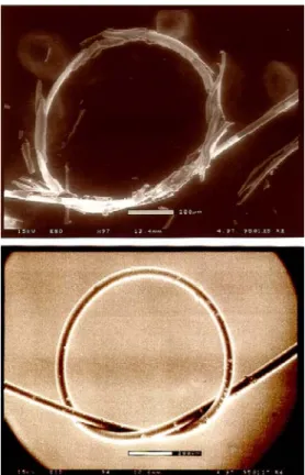
Limb et al7 developed a method to deposit fluorocarbon films spectroscopically similar to PTFE using PECVD. The precursor used in this process was hexafluoropropylene oxide (HFPO). It was demonstrated that the chemical composition and physical properties could be tuned by pulsing the plasma excitation, as shown in Figure 1.2.7
Figure 1.2 Comparison of continuous PECVD (top) and pulsed PECVD (bottom) coating
of 75 µm diameter wires. In the pulsed PECVD case, the crosslinking density has been reduced below the percolation of rigidity, allowing the structural integrity of the coating to be maintained even after tying the wires into 800 µm diameter loops.7
Limb et al also used the PECVD technique to produce fluorocarbon coatings on components of neurological electrode assemblies, such as silicon microribbons and neural probes. Cross-sectional views of a coated microribbon are shown in Figure 1.3. Figure 1.4 shows a Huntington Medical Research Institute (HMRI) probe coated with a fluorocarbon film. The coating produced by PECVD is uniform up to the tip (which is 5 µm in diameter). Figures 1.3 and 1.4 demonstrate the ability to create conformal coatings on micron-scale components of neural prostheses using CVD.
Figure 1.3 Cross-sectional view of a CVD fluorocarbon coated silicon microribbon.
(a) Full view with scale bar = 20 µm. (b) Corner magnification with scale bar = 10 µm.
Figure 1.4 Environmental scanning electron micrograph of Iridium neural probe
1.4 Organosilicon Polymers
The use of organosilicon films prepared by CVD techniques as biomaterials has been investigated by several researchers. Organosilicon coatings on Celgard®-2400 and Silastic® membranes were deposited from two cyclic silicone precursors (hexamethylcyclotrisiloxane and octamethylcyclotetrasiloxane) using PECVD by Chawla.12 The adhesion of platelets and leucocytes to the coated membranes was found to be lower than adhesion on untreated controls. Ishikawa et al13 obtained similar results in their investigation of platelet adhesion on glass slides coated with organosilicon thin films. Hasirci14 examined the effect of organosilicon coatings on activated charcoal (used in hemoperfusion). The coatings were deposited from hexamethyldisiloxane by PECVD. The damage to platelets, erthrocytes, and leucocytes in blood normally caused by charcoal granules was significantly reduced by the silicone coating.
Some of the characteristics of silicones are more desirable than those of fluorocarbons for biopassivation applications. Most importantly, the chemical nature of silicones enables covalent bond formation with the native silicon dioxide layer on silicon substrates, creating excellent adhesion.15 The high strength of a covalently bonded interface is desired for
long-term protection of the surface. Furthermore, silicone polymers synthesized by CVD have a lower degree of surface roughness compared to fluorocarbon films.16 Having smooth surfaces is necessary to minimize tissue damage in the immediate vicinity of the implant.
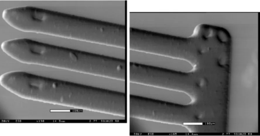
Organosilicon coatings on silicon microribbons and neural probes were examined by Pryce Lewis et al. As in the case of fluorocarbon films, the PECVD technique was found to be an effective method for coating these micron-scale, three-dimensional objects. Figures
1.5 and 1.6 show PECVD organosilicon coatings on a silicon microribbon cable and a University of Michigan (UM) neural probe, respectively.
Figure 1.5 Pulsed plasma enhanced CVD organosilicon coated silicon microribbon cable.17
1.5 Fluorocarbon-Organosilicon Copolymers
When considered separately, fluorocarbon and organosilicon polymers have several properties that are attractive for biopassivation applications. Fluorocarbon polymers have low dielectric constants, high resistivities, low surface energies, and high hydrophobicity. However fluorocarbon coatings have a high degree of surface roughness and their adhesion to silicon substrates is poor. Organosilicon polymers, on the other hand, adhere very well to silicon substrates and are smooth (low surface roughness). However, the electrical properties of organosilicon polymers such as dielectric constant and resistivity are not as attractive as those of fluorocarbons. A fluorocarbon-organosilicon copolymer therefore has the potential to incorporate the desirable attributes of each class of material into a single coating.
An important advantage of CVD is the ability to create copolymers that are difficult to synthesize by bulk or solution techniques, such as fluorocarbon-organosilicon copolymers. Organosilicon polymers having fluorocarbon pendant groups of the form CH2CH2(CF2)xCF3
as well as polymers having short fluorocarbon segments attached to siloxane chains have been synthesized by solution chemistry techniques.19-22 CVD offers an easier route to the production of these polymers as the process does not involve a solvent and can be performed in a single step.
Few attempts have been made to create fluorocarbon-organosilicon copolymers by CVD, and these have been limited to plasma-enhanced CVD.23-27 Sakata et al23 obtained thin films using hexamethyldisiloxane (HMDSO) and tetrafluoromethane (CF4) by
plasma-enhanced CVD. The structure of the films was found to be different from a simple blend of fluorocarbon and organosilicon polymers. In other words, the polymer film did not consist of
simple block or random copolymers. The authors observed the presence of Si-F bonds, and the data presented indicates that most of the fluorine in the films was bonded to silicon.
Similar results were obtained by Kim et al24 with HMDSO and perfluorobenzene (C6F6). This investigation also included dielectric constant measurements and adhesion tests.
The dielectric constants of the copolymer films were found to lie between those of the respective homopolymeric films, between 2 (pure fluorocarbon) and 4 (pure organosilicon). Annealing the films brought about a slight decrease in the dielectric constant. Adhesion of these films to silicon substrates was measured using the ASTM tape test28 and was determined to be better than that of pure fluorocarbon films.
Favia et al27 investigated the plasma-enhanced CVD of a cyclic fluorinated siloxane, (3,3,3-trifluoropropyl)methylcyclotrisiloxane. The authors examined the effects of varying substrate temperature and substrate bias on the deposition rate and chemical composition of the films. Films deposited with substrate temperatures below 200°C were determined to be structurally similar to the precursor. The carbon and hydrogen content of the films was found to decrease at higher substrate temperatures along with the deposition rate. Increasing the substrate bias resulted in greater crosslinking and higher deposition rate. The authors emphasize the absence of Si-F, Si-H and O-H bonds in their films.
In all of the above investigations, the fluorocarbon-organosilicon materials produced had poorly defined chemical structures due to the low selectivity of the PECVD technique. Having a well-defined chemical structure is essential in order to understand the structure-property-processing relationships of a material. A good understanding of these relationships is, in turn, vital for the development of a biopassivation coating that has all of the desired characteristics.
The objective of this thesis is to investigate the synthesis of fluorocarbon-organosilicon copolymer thin films using the more selective HFCVD technique and evaluate the chemical and physical properties of these films. While synthesizing an effective biopassivation coating is the primary goal of this work, this thesis also explores applications for fluorocarbon-organosilicon copolymers beyond the realm of neural prostheses.
1.6 Thesis Framework
Chapter Two reports a preliminary attempt to synthesize fluorocarbon-organosilicon
copolymer thin films by HFCVD. Rigorous chemical characterization confirms the copolymeric nature of the films. The characterization methodologies described in this chapter are used extensively in subsequent chapters.
Chapter Three describes the use of an initiator in the HFCVD synthesis of
fluorocarbon-organosilicon copolymers. The similarity between this HFCVD synthesis and conventional free radical polymerization in solution is highlighted.
Chapter Four examines the role of filament temperature in the HFCVD of
fluorocarbon-organosilicon copolymers using an initiator. Profound differences in chemical structure are observed in the range of filament temperatures examined. These differences give rise to significant changes in thermal and mechanical properties.
Chapter Five describes a technique for grafting chains of poly(acrylamide) onto
fluorocarbon-organosilicon films produced by HFCVD. This is the first step in an effort to create bioactive surface coatings by using the techniques of CVD and solution chemistry in combination.
Each technical chapter is structured as a journal article, beginning with a brief introduction, followed by a description of experimental methods, presentation of results and discussion, and finally ending with conclusions. The chapters are arranged in a manner that provides continuity within the thesis. Some additional experimental results are presented and discussed in the Appendix. The thesis concludes with a summary of the work accomplished and suggestions for future work.
1.7 References
1. Pedotti, A., Ferrarin, M., Quintern, J. and Riener, R. Neuroprosthetics: from Basic Research to Clinical Application (Springer-Verlag, Berlin, 1996).
2. Nichols, M. F. Crit. Rev. Biomed. Eng. 22, 39 (1994).
3. Yasuda, H. Plasma Polymerization, (Academic Press, Orlando, Florida, 1985). 4. Wrobel, A. M. and Czeremuszkin, G. Thin Solid Films 216, 203 (1992). 5. Yasuda, H. and Hsu, T. J. Polym. Sci., Polym. Chem. Ed. 15, 81 (1977).
6. Limb, S. J., Edell, D. J., Gleason, E. F. and Gleason, K. K. J. Appl. Polym. Sci. 67, 1489 (1998).
7. Limb, S. J., Gleason, K. K., Edell, D. J. and Gleason, E. F. J. Vac. Sci. Technol. A 15, 1814 (1997).
8. Limb, S. J. Ph.D. Thesis (Massachusetts Institute of Technology, Cambridge, Massachusetts, 1997).
9. Limb, S. J., Labelle, C. B., Gleason, K. K., Edell, D. J. and Gleason, E. F. Appl. Phys. Lett. 68, 2810 (1996).
10. d'Agostino, R., Cramarossa, F., Fracassi, F. and Illuzzi, F. in Plasma Deposition, Treatment, and Etching of Polymers (ed. d'Agostino, R.) 95 (Academic Press, San Diego, 1990).
12. Chawla, A. S. Biomaterials 2, 83 (1981).
13. Ishikawa, Y., Sasakawa, S., Takase, M., Iriyama, Y. and Osada, Y. Makromol. Chem., Rapid Commun. 6, 495 (1985).
14. Hasirci, N. J. Appl. Polym. Sci. 34, 2457 (1987).
15. Wrobel, A. M. and Wertheimer, M. R. in Plasma Deposition, Treatment, and Etching of Polymers (ed. d'Agostino, R.) 163 (Academic Press, San Diego, 1990).
16. Murthy, S. K. and Gleason, K. K. unpublished results
17. Pryce Lewis, H. G., Edell, D. J. and Gleason, K. K. Chem. Mater. 12, 3488 (2000). 18. Pryce Lewis, H. G. and Gleason, K. K. unpublished results
19. Owen, M. J. and Kobayashi, H. Macromol. Symp. 82, 115 (1994).
20. Owen, M. J. in Block Copolymers Science and Technology (ed. Meier, D. J.) 3, 129 (MMI Press, Midland, 1983).
21. Doeff, M. M. and Lindner, E. Macromolecules 22, 2951 (1989). 22. Chen, G. J. and Tamborski, C. J. Organomet. Chem. 293, 313 (1985). 23. Sakata, J., Yamamoto, M. and Tajima, I. J. Polym. Sci. A 26, 1721 (1988). 24. Kim, D. S., Lee, Y. H. and Park, N. Appl. Phys. Lett. 69, 2776 (1996).
25. Kitoh, H., Muroyama, M., Sasaki, M. and Iwasawa, M. Jpn. J. Appl. Phys. 35 (2B), 1464 (1996).
26. Shirafuji, T., Miyazaki, Y., Nakagami, Y., Hayashi, Y. and Nishino, S. Jpn. J. Appl. Phys. 38 (7B), 4520 (1999).
27. Favia, P., Caporiccio, G. and d'Agostino, R. J. Polym. Sci. A 32, 121 (1994). 28. ASTM Designation D 3359 - 95, American Society for Testing and Materials.
Chapter Two
Fluorocarbon-Organosilicon Copolymer Synthesis by
Hot Filament Chemical Vapor Deposition
Abstract
Hot-filament chemical vapor deposition has been used to deposit copolymer thin films consisting of fluorocarbon and organosilicon groups from hexafluoropropylene oxide (HFPO) and hexamethylcyclotrisiloxane (D3). This method offers an easy route to the
production of such copolymers as the process does not require a solvent and can be performed in a single step. The presence of covalent bonds between the fluorocarbon and organosilicon moieties in the thin films has been confirmed by infrared spectroscopy; X-ray Photoelectron (XPS); and solid-state 19F, 13C and 29Si nuclear magnetic resonance (NMR) spectroscopy. The film structure consists of chains with linear and cyclic siloxane groups and CF2 groups as repeat units. Crosslinking and termination occur mainly via the siloxane
units.
Acknowledgments
We gratefully acknowledge the support of the NIH under contract NO1-NS-9-2323. In addition, this work made use of MRSEC Shared Facilities supported by the NSF under award DMR-9400334. We would also like to thank Bradley D. Olsen for preparing samples for NMR analysis. B.D. Olsen was supported by the Paul E. Gray Fund for undergraduate research at MIT.
2.1 Introduction
Fluorocarbon and organosilicon thin films produced by chemical vapor deposition have a wide variety of applications, ranging from biocompatible coatings for medical implants1-6 to low-κ dielectrics in integrated circuits.7-13 Fluorocarbon films have been found to be
biocompatible and to have low dielectric constants. Organosilicon films with cross-linked siloxane groups offer the advantage of superior thermal stability [relative to linear poly(dimethylsiloxane)].14 Further, they adhere well to silicon substrates by means of covalent bonds formed with the native oxide on the silicon surface.15 A fluorocarbon-organosilicon copolymer film therefore has the potential to incorporate the desirable attributes of each class of material into a single film.
Silicone or fluorocarbon homopolymers can be coated onto surfaces by a number of techniques such as spin-on coating, casting, or chemical vapor deposition. An important advantage of chemical vapor deposition (CVD) is the ability to create copolymers that are difficult to synthesize by bulk or solution techniques, such as fluorocarbon-organosilicon copolymers. Organosilicon polymers having fluorocarbon pendant groups of the form CH2CH2(CF2)xCF3 as well as polymers having short fluorocarbon segments attached to
siloxane chains have been synthesized by solution chemistry techniques.16-19 CVD offers an easier route to the production of these polymers as the process does not involve a solvent and can be performed in a single step.
Among the different CVD techniques available, hot-filament CVD (HFCVD, also known as pyrolytic or hot-wire CVD) is unique in several respects. First, HFCVD does not require the generation of a plasma, thereby avoiding defects in the growing film produced by UV irradiation and ion bombardment. In addition, films produced by HFCVD have
better-defined chemical structures because there are fewer reaction pathways than in the less selective plasma-enhanced CVD method. Further, HFCVD has been shown to produce films that have low degrees of crosslinking.20 Co-deposition of fluorocarbon and organosilicon precursors has been performed using plasma enhanced CVD methods,21-23 but the resulting films had complex structures without clearly defined spectroscopic features.
HFCVD has been used to deposit fluorocarbon films that are spectroscopically similar to poly(tetrafluoroethylene) (PTFE),20 as well as organosilicon films that consist of linear and cyclic siloxane repeat units.24 The precursors used in these investigations were hexafluoropropylene oxide (HFPO) and hexamethylcyclotrisiloxane (D3), respectively. The
primary propagating unit in the fluorocarbon films was difluorocarbene, generated by the pyrolysis of HFPO. In the case of the organosilicon films, the decomposition of D3 was
postulated to occur in two ways: by the breakdown of the rings into dimethylsilanone and by methyl abstraction from the six-membered ring structure, giving rise to the linear and cyclic repeat units, respectively.
This paper describes the deposition of fluorocarbon-organosilicon copolymer thin films by HFCVD from HFPO and D3. The copolymer films have well-resolved bonding
environments and extensive spectroscopic characterization confirms the presence of covalent bonds between CF2 groups and siloxane-based polymeric units in the film.
2.2 Experimental Section
Depositions were performed in a custom-built vacuum chamber on to silicon wafer substrates. The pressure within the chamber was controlled by a butterfly valve connected to an MKS type 252 exhaust valve controller. Substrates were placed on a stage maintained at a low temperature (15 ± 5 °C) by the circulation of chilled water through internal coils. Precursor breakdown was achieved by means of a resistively heated 0.038-cm-diameter Nichrome wire (80% nickel, 20% chromium; Omega Engineering). The frame holding the filament wire was equipped with springs to compensate for thermal expansion of the wire upon heating. The distance between the filament wire and the substrate was 1.4 cm. The filament temperature was measured by a 2.2-µm infrared pyrometer. The spectral emissivity was estimated to be 0.85 based on direct-contact thermocouple experiments.
The flow of HFPO gas (donated by DuPont) into the chamber was controlled by an MKS model 1295C mass flow controller (MFC). The silicone precursor, D3 (Gelest) was
vaporized in a stainless steel vessel that was heated to 90 ± 5 °C. The lines leading from the vessel to the vacuum chamber were maintained at 130 ± 5 °C. The flow of vapor from the vessel into the chamber was regulated by a needle valve.
Prior to the deposition of copolymer film, the filament wire was preconditioned by being heated at a constant voltage of 86.5 V and under a flow of HFPO into the reactor at 30 sccm for 20 min at a chamber pressure of 1 Torr. Following this treatment, the power to the filament was turned down over a 5-min span, and the chamber was pumped up to atmospheric pressure to facilitate cleaning and placement of a 4-in. wafer on the stage.
Depositions were performed at a filament temperature of 620°C and a chamber pressure of 1 Torr. The precursor flow rates were 20 sccm for HFPO and 28 sccm for D3.
The duration of these depositions ranged between 10 and 30 min. The deposition rate, determined by profilometry, was approximately 250 Å/min.
Fourier-transform infrared (FTIR) spectroscopy was performed on the deposited films using a Nicolet Magna 860 spectrometer in transmission mode. The spectra were baseline-corrected and normalized to a thickness of approximately 7000 Å. X-ray photoelectron spectroscopy (XPS) was carried out on a Kratos Axis Ultra spectrometer using a monochromatized aluminum K α source.
Solid-state NMR spectroscopy was performed on a home-built spectrometer comprising a 6.338 T Oxford superconducting magnet and a 3.2-mm Chemagnetics magic angle sample spinning (MAS) probe. For this analysis, approximately 14 mg of film was scraped off wafers from nine 30-min depositions, and packed into a zirconia rotor of 11 mm3 internal volume. Sample spinning at the magic angle of 54.7° was performed in order to mitigate spectral broadening due to strong homonuclear dipolar and anisotropic chemical shift effects. The sample spinning speeds were 5, 25, and 10 kHz for 29Si, 19F and 13C,
respectively.
29Si NMR experiments were performed with proton cross-polarization (CP) and proton
decoupling to enhance the signal and resolution from the low-natural-abundance 29Si nuclei. The 1H-29Si CP time was 5ms (as determined by contact-time experiments performed by Pryce Lewis et al.24), and the 90° pulse width was 1.3 µs. 29Si spectra were also obtained with fluorine cross-polarization and fluorine decoupling. The purpose of this was to determine which silicon atoms were in close proximity (<10 Å) to fluorine-containing moieties. Contact time experiments indicated that a CP time of 5 ms was sufficient to
maximize signal intensity. The 90° pulse width for these measurements was 1.2 µs. 29Si chemical shifts were externally referenced to tetramethylsilane.
19F NMR spectra were obtained by direct polarization with a 90° pulse width of 1.2 µs.
Chemical shifts were externally referenced to trichlorofluoromethane. 13C spectra were obtained by direct polarization with proton decoupling as well as direct polarization with fluorine decoupling. The 90° pulse width was 1.8 µs for both types of spectra. 13C chemical shifts were externally referenced to tetramethylsilane.
2.3 Results and Discussion
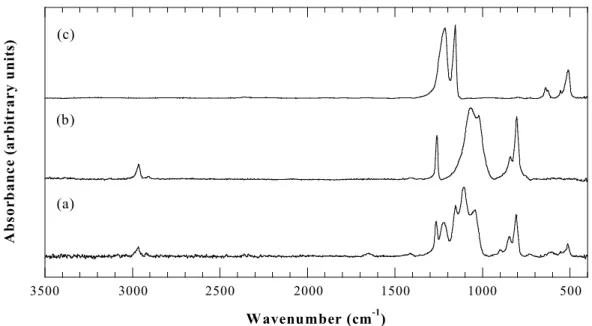
Fourier Transform Infrared (FTIR) Spectroscopy. Figure 2.1 shows the FTIR
spectrum of a copolymer film compared with the spectra of homopolymeric fluorocarbon and silicone films obtained from HFPO and D3, respectively. Table 2.1 gives the absorption band
assignments from the literature. All of the bands associated with the pure-fluorocarbon20 and
the pure-silicone film24 appear in the hybrid film, although slight shifts in position occur in some of the bands.
The FTIR bands in all three HFCVD films in Figure 2.1 are relatively narrow (fwhm of ~ 60 cm-1 or less), aiding in the resolution of specific chemical environments. For example, the symmetric (1155 cm-1) and asymmetric (1223 cm-1) CF
2 stretches can be clearly resolved
in Figure 2.1c. In plasma-deposited films, there is typically only one broad band in the 1100-1500-cm-1 region20 resulting from overlap of several types of C-F bonding environments. The narrowness of the FTIR bands thus indicates the structural simplicity of the HFCVD copolymer films.
500 1000 1500 2000 2500 3000 3500 A b so rb an ce ( a rb it ra ry u n it s) W avenumber (cm-1) (a) (c) (b)
Figure 2.1 FTIR spectra of (a) copolymer, (b) silicone, and (c) fluorocarbon films, all
deposited by HFCVD under the same conditions.
Table 2.1 Absorption band assignments for FTIR spectra.
assignment copolymer (cm-1) literature (cm-1) ref
CF2 rocking 514 516-520 37, 38
CF2 wagging 610 650 39
Si-C stretching, CH3 rocking in Si-Me2 808 805 40
Si-C stretching, CH3 rocking in Si-Me3 848 845 40
Si-C stretching, CH3 rocking in Si(Me)2(CF2) 899 N/A N/A
Si-O-Si asymmetric stretching 1043; 1107 1050 40
CF2 symmetric stretching 1155 1160 39
CF2 asymmetric stretching 1223 1220 39
CH3 symmetric bending in Si-Mex 1265 1260 40
CH symmetric stretching in sp3 CH
3 2913 2900 40
The asymmetric stretching mode (ASM) of the siloxane (Si-O-Si) group is also easily resolved. The region around these bands in the copolymer spectrum is expanded for detail in Figure 2.2. The ASM appears as a doublet, as in the case of poly(dimethylsiloxane) chains with three or more siloxane units or ring structures of more than eight siloxane units.25, 26 Both peaks of this doublet in the copolymer film (1043 and 1107 cm-1) are shifted towards higher wavenumbers relative to the pure-silicone film (1020 and 1068 cm-1). No shift would be expected if the fluorocarbon and organosilicon moieties were simply depositing together as two independent phases. Also, it is known27 that electronegative substituents on the silicon atom increase the Si-O stretching frequency. Hence, the shift of the ASM is consistent with copolymerization, where bonds are formed between silicon atoms and CF2
groups. 600 800 1000 1200 1400 Wavenumber (cm-1) A b so rb a n ce ( a rb it ra ry un it s) SiOSi CF2 Si-C CF2 CH3
Two other modes (rocking and wagging) of the CF2 groups appear at 514 and 610 cm-1
in the copolymer spectrum. The band at 610 cm-1 is shifted relative to its position in the pure-fluorocarbon spectrum (620 cm-1). This shift towards lower wavenumbers is consistent with the shift of the ASM in the opposite direction, an effect of the redistribution of electron density caused by copolymerization.
In the pure-silicone film, Si-C stretching bands appear at 808 and 848 cm-1. The copolymer spectrum contains both of these bands, as well as a third band at 899 cm-1. The Si-C stretching mode is dependent on the vibrations of the substituents on the silicon atom.28 Hence, it is likely that the band at 899 cm-1 is due to the Si-C stretching mode of a siloxane moiety that has both methyl and CF2 substituents bonded to silicon.
The bands at 2913 and 2967 cm-1 represent the symmetric and asymmetric stretching modes of the CH bond in sp3 CH3 respectively. The absence of sp3 CH2 bands indicates that
there is no crosslinking through methylene bridges.
X-Ray Photoelectron Spectroscopy. Table 2.2 summarizes atomic composition data
obtained from a survey scan. The Si/O ratio is approximately 1:1.13. The high-resolution Si (2p) scan (not shown) contains a single peak with no apparent shoulders. The line width of this peak is slightly larger than that for a film deposited under the same conditions using D3
only. Hence, while the Si/O ratio suggests that the silicon atoms in the copolymer film are almost entirely in the +2 oxidation state, the line width of the Si (2p) peak indicates the possibility of a small concentration of different oxidation states.
A C 1s high-resolution scan (Figure 2.3) indicates the presence of only two types of carbon moieties, CF2 and CH3. The respective assignments at 290.0 eV and 282.8 eV were
that most of carbon present is in the form of either CF2 or CH3 will greatly simplify the
process of making peak assignments in the NMR spectra.
The XPS survey scan also detected small amounts of nickel and chromium in the film (<1.5 atomic %). Because no copolymer film was produced with a tantalum filament of equivalent diameter under the same conditions, this observation suggests that Nichrome plays a catalytic role in the process.
Table 2.2 XPS survey scan data.
binding energy (eV) element atomic concentration (%) 101 Si (2p) 13.55 283 C (1s) 30.70 531 O (1s) 15.33 576 Cr (2p) 0.48 687 F (1s) 38.42 859 Ni (2p) 1.53 278 280 282 284 286 288 290 292 294
Binding Energy (eV)
Figure 2.3 Carbon (1s) high-resolution scan of the HFCVD copolymer film
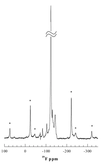
Solid-State Nuclear Magnetic Resonance Spectroscopy. The 19F NMR spectrum of the copolymer film is shown in Figure 2.4, with spinning sidebands labeled by asterisks. The remaining seven peaks represent resolved isotropic chemical shifts for fluorine. The chemical shift assignments are listed in Table 2.3. 19F spectra of homopolymeric fluorocarbon films deposited by the same technique20 show three peaks: CF2CF2*CF2 at –
123 ppm, CF3CF2*CF2 at –128 ppm, and CF3*CF2 around –84 ppm. All three of these peaks
are present in Figure 2.4.
-300 -200 -100 0 100 19 F p pm * * * * * *
Figure 2.4 Solid-state 19F NMR spectrum of the HFCVD copolymer film. The feature at -72 ppm is a spectrometer artifact.
Table 2.3 Chemical shift assignments for the 19F NMR spectrum. chemical shift
(ppm) structure % area ref
-83.6 CF3*CF2 1.65 41-47 -104.5 CF2*O 2.97 48 -123.4 CF2CF2*CF2 70.30 41-47 -128.0 CF3CF2*CF2 0.08 41-47 -131.1 CF2CF2*Si 6.27 29 -135.3 CF3CF2*Si 1.10 29 -144.4 SiCF2*Si 17.63 29
The assignments for the peaks at –131.1, –135.3 and –144.4 ppm are based on chemical shifts reported for various Si-CF2 environments in perfluoro(alkylsilanes) by Sharp
et al.29 It is postulated that these peaks correspond to CF2CF2*Si, CF3CF2*Si, and SiCF2*Si,
respectively. The side bands that appear at –46 and –243 ppm are associated with the SiCF2*Si peak, indicating a broad chemical shift tensor and a lack of mobility of the fluorine
atoms in this environment. The 19F spectrum also indicates the presence of a small number of CF2O linkages (-104.5 ppm). These linkages could form as a result of copolymerization
of CF2 units and linear siloxane chains.
The presence of Si-CF3 linkages was ruled out on the basis of 19F and 19Si NMR
experiments performed on a model compound [CF3-Si-(CH3)3]. The observed 19F and 29Si
shifts for this compound were –27.8 and –36.2 ppm, respectively.
Figure 2.5 shows the 13C NMR spectra obtained with 1H and 19F decoupling. Chemical shift assignments for these spectra are summarized in Table 2.4. Assignments for peaks i-iii
are taken from the literature.30-34 In these spectra, the CH3 and CF2 peaks are the most
intense; hence, the NMR analysis of the bulk film is in qualitative agreement with the surface analysis by C (1s) high-resolution XPS (Figure 2.3). As expected, the CH3 peak is narrowest
in the proton-decoupled spectrum, while the CF2 and CF3 peaks are narrowest in the
fluorine-decoupled spectrum. There is a small amount of CF3, evidenced by the presence of a
shoulder on the peak at 118.6 ppm.
0 40 80 120 13 C ppm (b) (a)
Figure 2.5 Solid-state 13C NMR spectra of the HFCVD copolymer film obtained with (a) 1H and (b) 19F decoupling.
Table 2.4 Chemical shift assignments for the 13C NMR spectra.
peak chemical shift (ppm) structure % area
i 0 CH3 62.0
ii 112 CF2 29.4
iii 119 CF3 1.1
Given the appreciable content of SiCF2*Si in the 19F spectrum, it seems likely that this
moiety would also appear in the 13C spectra. The peak at 131 ppm narrows considerably under fluorine decoupling and is therefore postulated to represent the SiCF2Si moiety. This
hypothesis was tested by performing the calculation described below.
In the 19F spectrum, the contribution of fluorine atoms to the SiCF2Si (peak area/2) was
divided by the sum of the contributions from all of the fluorine atoms [(sum of all CF2 peak
areas)/2 + CF3 peak area/3]. From the 13C spectrum, the peak area of SiCF2Si was divided by
the total area occupied by fluorocarbon groups (peaks ii-iv). The resulting values are in agreement (within 10%), supporting the respective assignments in the 19F and 13C spectra. These assignments are further substantiated by the 19F and 13C NMR data reported for a related molecule (FMe2Si-CF2-SiMe2F) by Fritz and Bauer.35 However, this type of linkage
does not account for all of the CF2 groups in the film as the 19F NMR spectrum indicates that
a significant fraction of the CF2 groups is linked to other fluorocarbon groups. The
possibility of having CF2 chains that are not linked to any organosilicon moiety cannot be
ruled out.
The 29Si NMR spectra obtained with 1H and 19F cross-polarization and dipolar
decoupling (CP/DD) are shown in Figure 2.6, with the peak assignments listed in Table 2.5. Although the CP/DD method increases sensitivity, the peak areas do not yield quantitative concentrations. This is in contrast to the 19F and 13C NMR spectra, which were obtained by direct polarization. The limited amount of film available precluded the use of direct polarization for 29Si NMR spectroscopy.
-120 -100 -80 -60 -40 -20 0 20 40 29 Si ppm (a) (b)
Figure 2.6 Solid-state 29Si NMR spectra of the HFCVD copolymer film obtained with (a) 1H and (b) 19F cross-polarization and decoupling.
Table 2.5 Chemical shift assignments for the 29Si NMR spectra. chemical shift (ppm) structure 0 (CH3)2Si(O)(CF2) -6.4 o-R3 -15.5 (O)2Si(CH3)2 -92.0 (O)2Si(CF2)2 -112.0 (O)3Si(CF2)
The narrowing effect of 1H decoupling is greatest for the peaks at 0, -6.4 and –15.5 ppm, indicating that these silicon environments are in the vicinity of hydrogen. The most intense of these peaks (-15.5 ppm) is assigned to the D unit [(O)2Si(CH3)2)] assuming a small
shift relative to its –19 ppm position in spectra of films deposited from pure D3.24 This
downfield shift is attributed to the effect of electronegative CF2 groups bonded to
neighboring siloxane groups and is consistent with the shifts observed in the FTIR spectrum of the copolymer (Figure 2.1c). Assuming a similar downfield shift, the peak at –6.4 ppm is assigned to the o-R3 environment in the copolymer film.
o-R3 represents a ring structure of three siloxane units that is bound to the film
structure by Si-Si bonds. The presence of these groups is attributed to a reaction pathway involving abstraction of one or more methyl groups in D3 with retention of the ring
structure.24 The absence of peaks at –9 and –19 ppm suggests that all of the siloxane ring structures have some degree of fluorocarbon substitution.
The peak at 0 ppm is assigned to linear siloxane units with two methyl groups and one CF2 unit bonded to each silicon atom. The proposed bonding to CF2 is consistent with the 0
ppm peak being the most prominent of the three peaks in this portion of the 19F cross-polarized and decoupled spectrum (Figure 2.6b). Also, because the CF2 group is less
electronegative than oxygen, this moiety must lie between the M group (Me3SiO, typically
observed at +6 ppm36) and the D group (-15.5 ppm). The combination of one CF
2 group and
one oxygen atom would, however, cause the silicon atom to appear as Si+2 in the XPS spectrum. The FTIR band at 899 cm-1 is probably due to the Si-C stretching mode in this moiety.
The peak at –92.0 ppm is most enhanced by 19F cross polarization and decoupling, indicating that CF2 and silicon are in close proximity. This peak is assigned to the
(O)2Si(CF2)2 moiety, as the large number of fluorine atoms would cause such an
(commonly known as “Q”) moiety in the literature (-105 to -110 ppm).36 Replacing two of the oxygen atoms with less-electronegative CF2 groups would cause a downfield shift. The
peak at –112.0 ppm is believed to be due to the (O)3Si*(CF2) moiety, which bears a closer
resemblance to the Q group. The peak is sharper in the 19F cross-polarized spectrum, indicating that it must be proximate to a fluorocarbon group. The oxidation state of silicon in (O)3Si(CF2) is +3, and the intensity of the peak indicates that only a very small amount is
present. This is probably why it is not easily resolved in the Si(2p) high-resolution scan.
Film Structure. The repeat units in the copolymer film consist of fluorocarbon units,
siloxane units, and linkages between them. Spectroscopic data indicate that the fluorocarbon content of the films is almost entirely in the form of CF2 and that siloxane D units are present
in both linear and cyclic form. There are four distinct types of copolymer linkages. The Si-CF2Si linkage can be present between siloxane rings or between rings and linear siloxane
groups. The (CH3)2Si(CF2)(O) link is linear, and could act as a junction between linear
siloxane segments and fluorocarbon units. (O)2Si(CF2)2 units are branch points, and can be
present in siloxane rings or in linear chains. The (O)3Si(CF2) unit, which is present in low
concentrations, is a cross-linking group. The presence of these different copolymer linkages suggests that the copolymer is random.
All of the siloxane rings in the film have some degree of CF2 substitution, and hence
these can also be considered as cross-linking groups and branch points. As there is no evidence of tertiary carbon, cross-linking and branching occur entirely via these siloxane moieties.
Chain termination takes place primarily with siloxane rings (Si-Si bonding between the repeat unit and the terminating ring). Termination could also occur by means of CF3CF2Si or
CF3CF2CF2, but the concentration of these linkages is small.
2.4 Conclusions
Fluorocarbon-organosilicon copolymer thin films can be synthesized by hot-filament CVD from HFPO and D3. Spectroscopic data (from XPS and FTIR and solid-state NMR
spectroscopies) indicate the presence of covalent bonds between the fluorocarbon and siloxane repeat units. The data also allow for the identification of different copolymer linkages. The film structure consists of chains with linear and cyclic siloxane groups, and CF2 groups as repeat units. Cross-linking and termination occur mainly via the siloxane
units.
2.6 References
1. Noort, R. v. and Black, M. M. in Biocompatibility of Clinical Implant Materials (eds. Williams, D. F.) 2, 79 (CRC Press, Boca Raton, 1981).
2. Chawla, A. S. Artif. Organs 3, 92 (1979). 3. Chawla, A. S. Biomaterials 2, 83 (1981).
4. Ocumpaugh, D. E. and Lee, H. L. in Biomedical Polymers (eds. Rembaum, A.and Shen, M.) 101 (Marcel Dekker, Inc., New York, 1971).
5. Thomson, L. A., Law, F. C., James, K. H. and Rushton, N. Biomaterials 12, 781 (1991).
6. Guidoin, R., Chakfe, N., Maurel, S., How, T., Batt, M., Marois, M. and Gosselin, C. Biomaterials 14, 678 (1993).
7. Moore, J. A. and Lang, C.-I. in Fluoropolymers (eds. Hougham, G., Cassidy, P., and Johns, K.) 1, 273 (Kluwer Academic/Plenum Publishers, New York, 1999).
8. Hougham, G., Tesoro, G. and Viehbeck, A. Macromolecules 29, 3453 (1996). 9. Lau, K. K. S. and Gleason, K. K. Mater. Res. Soc. Symp. Proc. 544, 209 (1999). 10. Rosenmayer, T. and Wu, H. Mater. Res. Soc. Symp. Proc. 427, 463 (1996). 11. Peters, L. Semicond. Int. 23, 108 (2000).
12. Loboda, M. J. Microelect. Eng. 50, 15 (2000).
13. Grill, A. and Patel, V. J. Appl. Phys. 85, 3314 (1999).
14. Michalczyk, M. J., Farneth, W. E. and Vega, A. J. Chem. Mater. 5, 1687 (1993). 15. Wrobel, A. M. and Wertheimer, M. R. in Plasma Deposition, Treatment, and Etching
of Polymers (ed. d'Agostino, R.) 234 (Academic Press, San Diego, 1990). 16. Owen, M. J. and Kobayashi, H. Macromol. Symp. 82, 115 (1994).
17. Owen, M. J. in Block Copolymers Science and Technology (ed. Meier, D. J.) 3, 129 (MMI Press, Midland, 1983).
18. Doeff, M. M. and Lindner, E. Macromolecules 22, 2951 (1989). 19. Chen, G. J. and Tamborski, C. J. Organomet. Chem. 293, 313 (1985).
20. Limb, S. J., Lau, K. K. S., Edell, D. J., Gleason, E. F. and Gleason, K. K. Plasmas and Polymers 4, 21 (1999).
21. Sakata, J., Yamamoto, M. and Tajima, I. J. Polym. Sci. A 26, 1721 (1988).
22. Shirafuji, T., Miyazaki, Y., Nakagami, Y., Hayashi, Y. and Nishino, S. Jpn. J. Appl. Phys. 38 (7B), 4520 (1999).
23. Kim, D. S., Lee, Y. H. and Park, N. Appl. Phys. Lett. 69, 2776 (1996).
24. Pryce Lewis, H. G., Casserly, T. B. and Gleason, K. K. J. Electrochem. Soc. 148 (12), F212 (2001).
25. Richards, R. E. and Thompson, H. W. J. Chem. Soc. 124 (1949). 26. Wright, N. and Hunter, M. J. J. Am. Chem. Soc. 69, 803 (1947).
27. Lin-Vien, D., Colthup, N., Fatteley, W. G. and Grasselli, J. G. The Handbook of Infrared and Raman Characteristic Frequencies of Organic Molecules, (Academic Press, New York, 1991).
28. Matsurra, H., Ohno, K., Sato, T. and Murata, H. J. Mol. Struct. 52, 13 (1979). 29. Sharp, K. G., Li, S. and Johannesen, R. B. Inorg. Chem. 15, 2295 (1976). 30. Ovenall, D. W. and Chang, J. J. J. Magn. Reson. 25, 361 (1977).
31. Kaplan, S. and Dilks, A. J. Appl. Polym. Sci.: Appl. Polym. Symp. 38, 105 (1984). 32. Mallouk, T., Hawkins, B. L., Conrad, M. P., Zilm, K., Maciel, G. E. and Bartlett, N.
Philos. Trans. R. Soc. Lond. A 314, 179 (1985).
33. Schwerk, U., Engelke, F., Kleber, R. and Michel, D. Thin Solid Films 230, 102 (1993). 34. Hagaman, E. W., Murray, D. K. and Cul, G. D. D. Energy Fuels 12, 399 (1998). 35. Fritz, G. and Bauer, H. Angew. Chem. Int. Ed. Engl. 22, 730 (1983).
36. Marsmann, H. in NMR: Oxygen-17 and Silicon-29 (eds. Diehl, P., Fluck, E., and Kosfeld, R.) 17, 65 (Springer-Verlag, New York, 1981).
37. Moynihan, R. E. J. Am. Chem. Soc. 81, 1045 (1959). 38. Liang, C. Y. and Krimm, S. J. Chem. Phys. 25, 563 (1956).
39. d'Agostino, R., Cramarossa, F., Fracassi, F. and Illuzzi, F. in Plasma Deposition, Treatment, and Etching of Polymers (ed. d'Agostino, R.) 95 (Academic Press, San Diego, 1990).
40. Rau, C. and Kulisch, W. Thin Solid Films 249, 28 (1994).
41. Emsley, J. W. and Phillips, L. Prog. NMR Spectrosc. 7, 1 (1971).
42. Dec, S. F., Wind, R. A. and Maciel, G. E. Macromolecules 20, 2754 (1987). 43. English, A. D. and Garza, O. T. Macromolecules 12, 351 (1979).
44. Harris, R. K. and Jackson, P. Chem. Rev. 91, 1427 (1991).
45. Kitoh, H., Muroyama, M., Sasaki, M. and Iwasawa, M. Jpn. J. Appl. Phys. 35 (2B), 1464 (1996).
46. Tonelli, C. and Tortelli, V. J. Fluorine Chem. 67, 125 (1994).
47. Tortelli, V., Tonelli, C. and Corvaja, C. J. Fluorine Chem. 60, 165 (1993).
48. Banks, R. E. Fluorocarbons and their Derivatives, 2nd ed., 237 (MacDonald Technical and Scientific, London, 1970).
Chapter Three
Initiation of Cyclic Vinylmethylsiloxane Polymerization
in a Hot-Filament Chemical Vapor Deposition Process
Abstract
The role of an initiator (perfluorooctane sulfonyl fluoride, PFOSF) in the polymerization of 1,3,5-trivinyl-1,3,5-trimethylcyclotrisiloxane (V3D3) by hot-filament
chemical vapor deposition (HFCVD) has been demonstrated. Use of the initiator allows rapid deposition of films at significantly lower filament temperatures. Polymerization is initiated when radical species produced by the pyrolysis of PFOSF react with V3D3. Chain
propagation occurs along the vinyl bonds of V3D3, resulting in chains with hydrocarbon
backbones and siloxane rings as pendant groups. Chains are terminated by fluorocarbon radicals, sulfonyl fluoride radicals or other propagating chains.
Acknowledgments
We gratefully acknowledge the support of the National Institutes of Health under contract NO1-NS-9-2323. B.D. Olsen was supported by the Paul E. Gray Fund for undergraduate research at MIT. In addition, this work made use of MRSEC Shared Facilities supported by the National Science Foundation under Award Number DMR-9400334. We also thank Dr. Kenneth Lau for helpful discussions.
3.1 Introduction
Hot-filament chemical vapor deposition (HFCVD) is a one-step method of producing polymeric thin films by thermal decomposition of a precursor gas. Thermal decomposition is achieved using a resistively heated filament, and the radical species generated by this process undergo polymerization reactions to form a film on the cooled surface of a substrate. In comparison to plasma-enhanced CVD, HFCVD produces films with better-defined chemical structures since there are fewer reaction pathways available. HFCVD has been used to produce homopolymeric fluorocarbon1 and organosilicon2 films, as well as fluorocarbon-organosilicon copolymer films.3 Fluorocarbon-organosilicon copolymers possess useful characteristics of fluorocarbon thin films (such as low surface energy and low dielectric constant) and organosilicon thin films (such as good adhesion to silicon substrates4 and low surface roughness2). HFCVD is a useful synthetic technique because the process can be carried out in a single step with no solvent. The properties of the resulting copolymer thin films can be tuned by changing the chemical composition of the feed gases. In addition, HFCVD allows the deposition of conformal coatings on substrates of various types and geometries.
The use of an initiator in HFCVD allows films to be deposited at significantly higher rates and provides greater control over chemical composition and morphology. This was demonstrated by Pryce Lewis et al for fluorocarbon films deposited from hexafluoropropylene oxide (HFPO) using perfluorooctane sulfonyl fluoride (PFOSF) as an initiator.5 In the mechanism proposed for film growth, the generation of free radicals from
the pyrolysis of PFOSF is the initiation step:
The fluorocarbon radical subsequently combines with the propagating species, difluorocarbene (CF2), which is generated by the pyrolysis of HFPO. The use of PFOSF
resulted in higher deposition rates, more efficient utilization of HFPO, and endcapping by CF3 groups.
This paper describes how PFOSF can be used as an initiator in the HFCVD of polymeric films from a cyclic vinylmethylsiloxane, 1,3,5-trivinyl-1,3,5-trimethylcyclotrisiloxane (V3D3). As in the case of fluorocarbon films, use of PFOSF allows
rapid deposition of films at relatively low filament temperatures. Spectroscopic characterization shows that chain propagation occurs by polymerization across the vinyl bonds of V3D3. This HFCVD process thus resembles classical free radical polymerization of
vinyl monomers driven by an initiator.6 The synthetic approach described in this work can be applied to other vinyl monomers. In addition, the combination of PFOSF with V3D3 results
in a fluorocarbon-organosilicon copolymer with unique chemical properties compared to those produced in past HFCVD work3 or by conventional synthesis.7-10
3.2 Experimental Section
Film depositions were performed on silicon wafers in a custom-built vacuum chamber, as described previously.3 For this work, the stage supporting the substrate was maintained at 25 ± 2 °C. Thermal excitation was achieved by a resistively heated 0.038-cm-diameter Nichrome wire (80% nickel, 20% chromium; Omega Engineering) without preconditioning. The filament to substrate spacing was 1.4 cm. The filament temperature was measured using a 2.2 µm infrared pyrometer with a spectral emissivity of 0.85. V3D3 (Gelest) was vaporized
in a stainless steel vessel that was heated to 110 ± 5 °C and fed to the reactor through a line maintained at 140 ± 5 °C. PFOSF (Aldrich) was vaporized in a glass container held at 60 ± 5 °C and fed through a line held at 90 ± 5 °C. The flow of both V3D3 and PFOSF into the
reactor was regulated by needle valves. Depositions were carried out at a range of filament temperatures between 350 and 540 °C with a chamber pressure of 0.5 Torr. For all depositions, the flow rates of V3D3 and PFOSF were 23 sccm and 12 sccm respectively.
Film thickness was measured by profilometry, using a Tencor P-10 Surface Profiler.
Chemical characterization was performed on a film deposited with a filament temperature of 370 °C. Fourier transform infrared (FTIR) spectroscopy was performed using a Nicolet Nexus 870 spectrometer in transmission mode. Solid-state nuclear magnetic resonance (NMR) spectroscopy was carried out using a home-built spectrometer consisting of a 6.338 T Oxford superconducting magnet and a 3.2 mm Chemagnetics magic angle sample (MAS) probe. Sample spinning speeds were 10 and 25 kHz for 13C and 19F, respectively. 13C NMR spectra were obtained by direct polarization with proton decoupling and also by direct polarization with fluorine decoupling. The 90° pulse width was 1.8 µs for both types of spectra. 13C chemical shifts were externally referenced to tetramethylsilane. 19F NMR spectra were obtained by direct polarization with a 90° pulse width of 1.2 µs. 19F
chemical shifts were externally referenced to trichlorofluoromethane. Other experimental details have been described previously.3