A BANDPASS SIGMA DELTA MODULATOR IF RECEIVER
by Emilija Simic
Submitted to the Department of Electrical Engineering and Computer Science in Partial Fulfillment of the Requirements for the Degrees of
Bachelor of Science in Electrical Science and Engineering
and Master of Engineering in Electrical Engineering and Computer Science at the Massachusetts Institute of Technology
February 2, 1997
OCT 2 91997
Copyright 1997 Emilija Simic. All rights reserved.
The author hereby grants to M.I.T. permission to reproduce distribute publicly paper and electronic copies of this thesis
and to grant others the right to do so.
Author
Certified b
Accepted
Depat~r ent of Electrical Engineering and Computer Science February 2, 1997
y
, -
L/-/ 7
A
Hae Seung (Harry) Lee
Thesis Supervisor by.
F. R. Morgenthaler Chairmab, Department Committee on Graduate Theses
A Bandpass Sigma Delta Modulator IF Receiver by
Emilija Simic
Submitted to theDepartment of Electrical Engineering and Computer Science February 2, 1997
In Partial Fulfillment of the Requirements for the Degree of Bachelor of Science in Electrical Science and Engineering
and Master of Engineering in Electrical Engineering and Computer Science
ABSTRACT
Within the context of the wireless communication systems, there is a concrete commercial interest in A/D conversion at IF stage of the receiver because this allows digital channel-select filtering, gain control and demodulation. Apart from reducing the analog filtering and
eliminating all the problems associated with analog I/Q demodulation and digitizing at 0 Hz, "digital receiver" has additional advantages of flexibility of digital programmability, as well as improved testability and yield. Unfortunately, the "digital receiver" places extremely high performance requirements on A/D converters, including high linearity to avoid interference, and high enough resolution to digitize large interferers so that final channel selection can be implemented on digital side. In a wideband systems, achieving necessary performance goals while still meeting the tight power constraints of mobile can ultimately set the limit to the application of this receiver architecture.
Motivated by the advantages of IF A/D conversion and the reported success of monolithic bandpass sigma-delta converters for narrowband applications, this thesis was set out to investigate whether the "digital receiver" architecture could be the architecture of choice for a wideband system, here for the CDMA path of the dual CDMA/analog mode phone receiver
for the 1.23 MHz band of the North American cellular standard. The thesis answers this question by focusing on modeling, design and implementation of the critical component of "the digital receiver" for the CDMA system, namely 10.5 bit bandpass sigma-delta converter with the oversampling ratio of 16, sampling frequency of 39.36 MHz and a signal band of 1.23 MHz, and verifying through simulations whether it achieves the performance equivalent to the
existing system in terms of the performance metric that was of crucial concern for this wideband system, namely power consumption. The results indeed compare favorably, verifying that the dual conversion "digital receiver" architecture with IF A/D conversion is a promising alternative to the existing dual conversion receiver with baseband A/D conversion for the CDMA system.
ACKNOWLEDGEMENTS
I would like to thank both my MIT and Qualcomm Incorporated thesis advisors, Professor Harry Lee and Principle Engineer Danny Butterfield, for their support during the course of my Master studies.
I am grateful to my coworkers at Qualcomm Incorporated. Special thanks are due to John Wetherell, for sharing his knowledge on sigma-delta modulators through numerous
discussions in the initial stages, and Seyfi Bazarjani, for invaluable support and enlightening technical advice in the latter stages of the project.
I would like to acknowledge Qualcomm Incorporated for their financial and technical
support.
Most of all, I thank my friend, Alex, for his love and companionship, my friend Jelena, for her humor and friendship, and my mother for her endless support.
TABLE OF CONTENTS
ABSTRACT
ACKNOWLEDGEMENTS
TABLE OF CONTENTS...I
LIST O F FIGURES...
...
... IV
LIST O F TABLES... ...
...
V II
CHAPTER 1 INTRODUCTION...
1
1.0 MOTIVATION AND GOAL ...
... 1
1.1 THESIS ORGANIZATION ...
... 4
1.2 OVERVIEW OF EXISTING SYSTEM ...
....
5
1.3 OVERVIEW OF PROPOSED SYSTEM...
7
1.4 BANDPASS SIGMA DELTA MODULATOR FOR CDMA SIGNAL
PA TH ...
...
8
1.4.1 THE ANALOG PART
9
1.4.1.1 THE ALTERNATIVE MODULATOR: SUB-SAMPLING
APPROACH ...
9
1.4.1.1.1 SUB-SAM PLIN G STAGE ... 9
1.4.1.1.2 IMAGE-REJECT FILTER ...
10
1.4.1.2 THE MODULATOR OF CHOICE:ANALOG
APPROACH ...
12
1.4.1.2.1 IMAGE-REJECT MIXER...
...
12
1.4.1.2.2 ANTI-ALIASING FILTER...14
1.4.2 THE DIGITAL PART...
15
1.4.3 BANDPASS SIGMA-DELTA A/D CONVERTER ... 15
1.4.3.1 DESIGN GOALS ...
...
16
1.4.3.2 SWITCHED CAPACITOR IMPLEMENTATION ... 17
1.4.3.3 CHOICE OF BAND LOCATION... 17
1.4.3.4 CHOICE OF SAMPLING FREQUENCY ... 18
1.5 SU M M A R Y ...
18
CHAPTER 2 BANDPASS SIGMA-DELTA ANALOG-TO-DIGITAL
CONVERSION OVERVIEW...
...
19
2.0 INTRODUCTION ...
19
2.1 SIN G L E L O O P ...
20
2.1.1 OPERATION MODELING ...
... 20
2.1.2 PERFORMANCE MODELING ... 29
2.2 MULTI-LOOP OR CASCADED BANDPASS SIGMA-DELTA
CONVERTERS ...
33
2.2.1 THE 4-2-2 ARCHITECTURE ... 34
2.2.1.2 PERFORMANCE MODELING ... 37
2.3 SUM M ARY ...
... 41
2.4 Appendix A...
41
CHAPTER 3 SYSTEM ARCHITECTURE...48
3.0 IN TRO D U CTIO N ...
48
3.1 CHOOSING THE ARCHITECTURE: CONSIDERATIONS
IN SIGMA-DELTA CONVERSION OF WIDE-BANDWIDTH
SY ST E M S ...
49
3.2 THE ARCHITECTURE OF CHOICE: SYSTEM LEVEL
DESIGN IN THE IDEAL CASE ...
52
3.2.1 CHOOSING THE SYSTEM PARAMETERS...
53
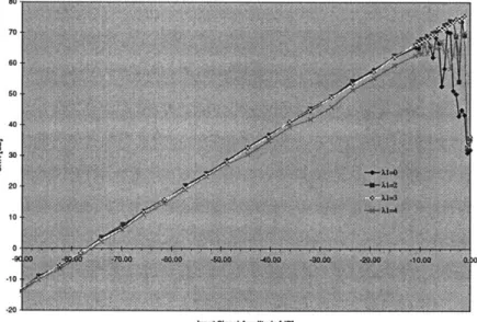
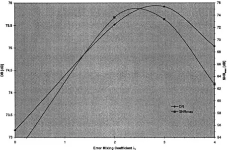
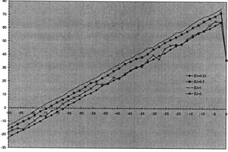
3.2.1.1 BEHAVIORAL SIMULATIONS AND RESULTS...54
3.2.2 MODELING THE BUILDING BLOCKS OF THE 4-2-2
ARCHITECTURE IN THE IDEAL CASE ...
63
3.3 SU M M A R Y ... 67
CHAPTER 4 CONVERTER DESIGN...
... 68
4.0 IN TRO D U CTIO N ... 68
4.1 FULLY DIFFERENTIAL PSEUDO TWO-PATH RESONATOR... 70
4.1.1 A M P L IF IE R D E SIG N ... 76
4.2 CIRCUIT NON-IDEALITIES ...
... 83
4.2.1 THE RESONATOR CIRCUIT NON-IDEALITITES...83
4.2.1.1 EFFECTS OF COMPONENT NON-IDEALITIES ON
THE RESONATOR PERFORMANCE ... 83
4.2.1.2 EFFECTS OF COMPONENT NON-LINEARITIES
ON THE RESONATOR PERFORMANCE ... 88
4.2.1.3 THE INTRINSIC RESONATOR CIRCUIT NOISE...91
4.2.1.4 THE THERMAL NOISE OF THE SWITCHES ... 92
4.2.1.5 THE INPUT REFERRED NOISE OF THE OP-AMPS....96
4.2.2 THE QUANTIZER AND 1 BIT D/A NON-IDEALITIES ... 99
4.2.3 SAMPLING CLOCK JITTER... ...
...
100
4.3 CONVERTER DESIGN ...
101
4.3.1 THE QUANTIZATION NOISE IN THE PRESENCE OF
M ISM ATCH ...
... ... 102
4.3.2 THE CIRCUIT N OISE...
104
4.3.2.1 THE RESONATOR CIRCUIT NOISE ... 104
4.3.2.1.1 THE THERMAL NOISE OF THE SWITCHES...107
4.3.2.1.2 THE INPUT REFERRED NOISE OF THE
OP AM PS ... ...
... 108
4.3.2.1.3 THE NOISE DUE TO THE FINITE
RESONATOR SPEED...109
4.3.2.1.4 THE NOISE DUE TO THE FINITE
AMPLIFIERS DC GAIN ... 13
4.3.2.1.5 RESONATOR NONLINEARITY ...
1...14
4.3.2.2 THE NOISE DUE TO THE IMPERFECTIONS IN
THE 1 BIT QUANTIZER AND 1 BIT D/A
C O N V E RT E R ...
114
4.3.3 THE NOISE DUE TO THE SAMPLING CLOCK JITTER...116
4.4 SIMULATION RESULTS AND DISCUSSION...117
4.5 SUM M ARY...
127
CHAPTER 5 IMPLEMENTATION ...
130
5.0 IN TRO D U CTIO N ...
130
5.1 POWER REDUCTION TECHNIQUES AND LOW VOLTAGE
O PE R A T IO N ...
133
5.2 THE RESONATORS ...
135
5.2.1 THE FIRST RESONATOR...
...
135
5.2.2 THE FIRST AM PLIFIER...137
5.2.3 THE SECOND, THIRD AND FOURTH RESONATORS ... 139
5.2.4 THE SECOND, THIRD AND FOURTH AMPLIFIERS ... 143
5.2.5 OP AMP BIAS CIRCUITRY ...
... 147
5.3 THE QUANTIZERS ...
148
5.4 CLOCK GENERATION CIRCUITRY...
158
5.5 SIMULATION RESULTS AND DISCUSSION ... 165
5.6 SUMMARY ...
166
CHAPTER 6 CONCLUCIONS...167
6.0 OVERVIEW ...
167
6.1 SU M M A R Y ... 168
6.2 CONCLUSIONS ... 169
6.3 FUTURE WORK ...
169
R E FE R E N C E S... 170
CHAPTER
1
INTRODUCTION
1.0 MOTIVATION AND GOAL
Within the context of communication systems, there is a concrete commercial interest in analog-to-digital (A/D) conversion at the intermediate-frequency (IF) stage of the receiver because this allows digital channel-select filtering, gain control and demodulation. Shifting in
phase/quadrature (I/Q) demodulation on digital side is one of the key advantages because digital local oscillators can produce high precision quadrature waveforms, avoiding the problems of phase and gain mismatch present in analog system. Reduction of analog IF filtering is another key advantage because besides being large and costly, analog IF filters generally have poorly controlled phase performance and therefore can induce intersymbol interference, while digital filters can have exactly linear phase. More functionality implemented on digital side provides an additional advantage of improved testability. The robustness of digital circuitry also produces advantages in manufacturing; it decreases cost by decreasing yield loss. Digital implementation allows the use of sophisticated algorithms which are especially useful with digitally coded transmissions (e.g. CDMA) and where multiple transmission standards are in use. Digital programmability allows a change in function to be implemented by a simple software change. Unfortunately, the "digital receiver" places extremely high performance requirements on A/D converters. It is of prime importance to have linearity, or else strong interferers may
intermodulate in the converter and mask the desired signal. The converter should have both high enough of a bandwidth to be able to convert the band of interest and high enough resolution (usually at least 10 bits) to be able to digitize large interferers, so that final channel selection can be performed on the digital side. To appreciate the issues involved, the past work on A/D converters has been consulted and Figure 1.1 summarizes the resolution and
Chapter 1: Introduction 120 110 100 90 80 z (n 70 60 50 40 1.E+02 * Oversampled ADCs o Nyquist-rate ADCs [10]
1.E+03 1.E+04 1.E+05 1.E+06 1.E+07 1.E+08
Signal Bandwidth [Hz]
Figure 1.1 SNR and signal bandwidth for oversampled and Nyquist-rate A/D converters
published during recent years. There are several observations to be made from it as follows: * There is a trade-off between the resolution in time and the resolution in amplitude inherent to A/D conversion.
* At low to medium conversion rates, oversampled A/D converters dominate the Nyquist rate converters in terms of achievable resolution.
* At higher channel bandwidths, Nyquist-rate converters dominate, but the achievable resolution is limited to below 70 dB due to component matching accuracy.
Due to an inherent trade-off between the conversion rate and the resolution of A/D
converters, requirement of having both high resolution and bandwidth necessary can be readily obtained for narrow-band systems, such as voice AM, IS-54 and AMPS cellular telephony or even GSM telephony. At higher channel bandwidths, such as 1.23 MHz band of the North American cellular standard IS-95, achieving high enough precision may be a very difficult task
Chapter 1: Introduction
by itself, and doing so while still meeting the tight power constraints of mobile is what ultimately can set the limit to the application of this receiver architecture. Therefore, we conclude that the "digital receiver" could be a practical approach only for sufficiently narrowband signals. Consequently, we would expect oversampled A/D converters to be converters of choice for this application area. As already noted, oversampled A/D converters can achieve high resolution without calibration or trimming due to their tolerance to
component mismatches and other circuit nonlinearities. They reduce the burden on analog circuitry, resulting in integration-friendly, simpler and more compact systems. Specifically, they don't require precision sample-and-hold circuitry and they relax performance requirements on the image rejection filter preceding the sampling. They have an inherent digital filtering capability and their resolution versus conversion rate is easily adjusted to allow the use of the same converter in variety of applications.
Sigma-delta oversampled A/D converters appear to be particularly suitable for the application area. They provide noise shaping that further attenuates the quantization noise in the band of interest, and as a result they require lower sampling frequency to achieve the same resolution as conventional oversampled A/D converters, potentially dissipating less power than conventional oversampled A/D converters.
The published work on bandpass converters verifies the conclusions drawn. Monolithic bandpass sigma-delta modulators have been reported [1]-[3] with center frequencies of 455 kHz, 1.8 kHz, 10.7 MHz, bandwidths of 10, 30, 200 kHz and resolutions of 10.5, 12.5 and 9.2 bits. These bandwidths are suitable for broadcast and voice AM, IS-54 cellular telephony, and GSM telephony, respectively. Another modulator obtained 9.2 bits of resolution with a 6.5 MHz center frequency and 200 kHz bandwidth using off-chip inductors as resonators [4]. There hasn't been any work reported on monolithic bandpass sigma-delta converters for higher channel bandwidths, although referring back to Figure 1.1, we notice that lowpass sigma-delta A/D converter designed by Brandt and Wooley in 1991 is a 12 bit converter for 1 MHz band
[5].
Motivated by the prospects of a simpler, more robust and more flexible system, and inspired by the reported success of monolithic bandpass sigma-delta converters for similar applications (for narrower signals though), this work is intended to investigate whether the "digital receiver" architecture could be the architecture of choice for the CDMA path of the dual CDMA/analog mode phone receiver. In particular, the motivation is to
Chapter 1: Introduction
* avoid all the problems associated with analog I/Q demodulation, such as phase and gain mismatch among I and Q paths,
* avoid all the problems associated with digitizing at 0 Hz, such as DC-offsets, * minimize the need for off-chip filtering,
* implement most of the selectivity processing on digital side, and * minimize the area and power dissipation.
Since oversampling with wideband signals necessarily implies fast clocking, there is a question though whether it will be possible to meet the power budget. This thesis will attempt to answer this question by focusing on design and implementation of a bandpass sigma-delta A/D
converter that would be able to convert an entire 1.23 MHz band of the North American cellular standard IS-95 and with enough resolution to do most of the channel selection on the digital side (here 10.5 bits). The results of this work will then serve as a benchmark in
comparing performances of the existing and proposed architectures, with the immediate goal of achieving at least the same level of performance in terms of power consumption.
1.1 THESIS ORGANIZATION
This thesis is organized in six chapters. First chapter summarizes the main features of the existing dual conversion receiver architecture with baseband A/D conversion, briefly discussing some of its main advantages and disadvantages. It also presents new "digital receiver"
architecture and discusses some of the system level decisions. The remainder of the thesis focuses on design of bandpass sigma-delta converter that is the heart of the new architecture, and will be used as a benchmark in comparing the performances of the existing and proposed architectures. Second chapter presents an overview of bandpass sigma-delta conversion, reviewing operation and performance modeling of two main converter architectural classes, single-loop and cascaded converters. Chapter 3 discusses the considerations in wide-bandwidth sigma-delta conversion, and presents the system level design in the ideal case. Chapter 4 identifies, discusses and quantifies relevant circuit non-idealities of the converter. Chapter 5 discusses the implementation of actual circuits that follows the design outlines arrived at in chapters 3 and 4, and presents the results of converter design. Finally, Chapter 6 draws the conclusions, comparing the performance of the new architecture to the existing one.
Chapter 1: Introduction
1.2 OVERVIEW OF EXISTING SYSTEM
Some of the system parameters for the physical layer of the communication link are given in Table 1-1. The portable operates in dual mode, providing CDMA or FM service, as indicated
in column one. Column two indicates the frequency allocated to these bands -the first range is for the base to portable link (receive section of portable's integrated receiver/transmitter), while the second is for the portable to base link (transmit section of portable's integrated receiver). The third column provides the bandwidth of the channel. The modulation used for each of the modes is indicated in the forth column. This system employs full duplex
(simultaneous transmission and reception), and shares a single antenna between the receiver and the transmitter through the use of duplex filters in a frequency-division duplex (FDD), as specified in column five. Finally, column six specifies the multiplex method used.
lable 1-1 iystem parameters tor the physical layer or the communication imnK
The existing architecture of the portable's receiver is shown in Figure 1.2. It is a multiple conversion design that converts the incoming signal first to an IF, at a relatively high frequency of approximately 85 MHz, and then directly to baseband [54].
The received signal is passed through a preselect bandpass filter which is responsible for
improving the dynamic range by rejecting out-of-band interferes. After preselection, a low noise amplifier (LNA) provides moderate gain to overcome losses in passive circuits up to the input of the first IF amplifier. This gain is needed to provide a good noise figure, but must be minimized to avoid degrading dynamic range. Next, another bandpass filter supplements the out-of-band attenuation provided by the preselect filter and serves as an image rejection filter by
I!
I
i!
i
1Chapter 1: Introduction
attenuating any noise at the image frequency that would be translated to IF1 (and thus folded onto the desired signal) in the mixing process. The mixer LOI=RF+IF1 then converts the signal to the IF1 where additional levels of gain are provided. Thereafter, there are two SAW bandpass filters, one for CDMA and one for FM, that perform channel selection. Automatic gain control (AGC) IF amplification is then employed so that amplitude information is retained. The signal is then quadrature mixed with L02 equal to the IF1, converting the signal directly to the baseband where final channel select filtering is performed with lowpass filter.
Figure 1.2 Block diagram of the existing receiver
This architecture has several important advantages over a single conversion super-heterodyne design. First, since preselect and image filters need to select band rather than channel, they will have wider bandwidth, lower Q and thus a smaller number of poles. Further, since the center of the second IF2 frequency is zero frequency, no image response is produced, and no image filtering is required for this second down-conversion. Signals above and below the desired signal frequency are translated into frequencies above or below DC, and are removed by lowpass filtering, rather than with a high-Q bandpass filter. As a result, this architecture benefits from low power A/D converters with small dynamic range and a small number of off-chip components.
Chapter 1: Introduction
There are several drawbacks to this architecture however, most of which stem from the fact that due to downconversion to baseband prior to A/D conversion, the in-phase/quadrature (I/Q) channel conversion had to be implemented on the analog side. First, this calls for two paths for each of the FM and CDMA signals, each path requiring a low pass filter and A/D converter, which increases the area. Second, it requires maintaining precision gain and phase matching between two paths in order to avoid image errors inside the path band. Next, DC-offsets voltages existing in active stages in the I and Q paths make the carrier components appear at 0 Hz or at output carrier frequency, requiring the employment of analog techniques for offset reduction, in order to prevent possible saturation of lowpass filters or A/D converters. Accordingly, there exists a need for an improved yet simpler receiver that would
* avoid the ambiguities, undesired signals and added noise caused by digitizing signals at 0 Hz, thus reducing the total area and power consumption.
* minimize the need for off-chip filtering, thus reducing cost.
* implement most of the selectivity processing on digital side, resulting in more robust and flexible system.
This thesis is intended as a proposal of such an alternate architecture for a CDMA path of a dual mode CDMA/FM receiver that will overcome the deficiencies of the existing system by minimizing the need for analog processing altogether.
1.3 OVERVIEW OF PROPOSED SYSTEM
A possible architecture to replace the dual conversion to analog baseband scheme is shown in Figure 1.3. Instead of mixing received signal from IF1 directly down to the baseband, the received signal is converted down to a non-zero lower IF2 where DC offsets cause no problem, and even-order distortion products have no effect, as is the case in any bandpass
system [35]. As before, the quadrature analog IF mixers are used, but now as image reject mixer. The 27dB of image rejection does not necessitate high phase shift accuracy, so that matching between the I and Q branches is no longer a critical concern. Furthermore, now the front end CDMA SAW filter can have relaxed specifications, and therefore reduced size and cost. Received signal is then digitized directly at IF2 using a bandpass sigma-delta converter, shifting I/Q demodulation and the final channel-select filtering to the digital side, where the digital local oscillator can produce high precision quadrature waveforms and the benefits of
Chapter 1: Introduction
digital signal processing can be applied to realize channel selection filters with very high
selectivity.
RF=869-894
F4
LOI=RF+IF1 L02=IF1+IF2
:IMAGE-REJECT MIXER
ANALOG PART DIGITAL PART
BANDPASS 1A MODULATOR
Figure 1.3 The architecture of the proposed system
1.4 BANDPASS SIGMA DELTA MODULATOR FOR CDMA SIGNAL PATH
Looking at Figure 1.3 we see that even though we relaxed specifications on SAW filter, we are
still using analog image reject mixer to convert the signal down to IF2, whereas one of the
original ideas was to minimize the need for analog processing. Couldn't we digitize the signal
directly at IF1, and shift all of the processing to digital side, i.e. achieve a perfect "digital
receiver"? Unfortunately not.
In order to meet power budget of the mobile receiver, we want A/D conversion to occur at as
low of sampling frequency fs as possible, much lower than IF1. In this system, the proposed
sampling frequency fs is 39.36 MHz and the proposed IF2 is 9.84 MHz, for reasons to be
discussed briefly. Since the
A/D
converter is a sampled-data system, having fs lower then IF1
will automatically result in down-conversion of a signal from IF1 to some lower frequency
IF1-fs, eliminating the need for analog mixers but still requiring elimination of image frequencies
using analog image reject filter prior to sampling.
How close can we get to the perfect "digital receiver"? On the surface, the sampling approach
has significant appeal, since it does not require the use of analog mixers. In reality, it is
Chapter 1: Introduction
implemented using "sub-sampling" approach to avoid the use of fast sampling clock which unfortunately poses high demands on image reject filter.
1.4.1 THE ANALOG PART
1.4.1.1 THE ALTERNATIVE MODULATOR- SUB-SAMPLING APPROACH
Conceptual block diagram of bandpass sigma delta modulator using sub-sampling techniques is given in Figure 1.4. Note that the sub-sampling stage is unnecessary, since the sampling
operation in A/D conversion performs the same function. It is drawn as a separate stage for discussion purposes only. A/D converter and the digital part are the same regardless of which technique is used, and will therefore not be discussed in this section.
x(t)@IF1 and
images@fi's IMAGE-REJECT x(t)@IF SUB-SAMPLING 1x[l]@F2 A BANDPASS y[n]@IF2 DIGITAL PART
FILTER STAGE A/D CONVERTER
fs=OSR*fb
x[nl=x(n*Ts)
Figure 1.4 Block diagram of the bandpass XA modulator based on sub-sampling approach
1.4.1.1.1 SUB-SAMPLING STAGE
As already pointed out, in reality both fs and IF2 must be much lower than IF1 in order to meet the power budget of the mobile's receiver. In order to convert the received signal from IF1 to IF2 without using really fast sampling clock, designers take advantage of the concept of sub-sampling. Namely, the received signal is sampled at much slower fs, which is chosen such that
IF1 + N*fs=IF2 where N is an integer:
Chapter 1: Introduction
IF1
COMPOSITE IMAGE-REJECT FILTER fb=1.23MHz
72dB
Thermal
Noise FloorI--IF1
2*IF2//
I
2*fsI
fs
I
N*fs IF1I
(N+1)*fsI
I
I I I
I I
I''
* Undesired Signals and Noise
* Undesired Signals and Noise at Image Frequencies * Desired Signal
Figure 1.5 Down-conversion using sub-sampling
1.4.1.1.2 IMAGE-REJECT FILTER
Unfortunately, in the process of sub-sampling, both the desired signal at IF1 and all undesired signals at image frequencies fi such that fi± n*fs=IF2 where n=1,2,3.... will be folded down to IF2. To solve this problem, an image-reject filter with bandwidth B<<2*IF2 and an
attenuation on the order of 72 dB for this system would be needed preceding the sub-sampling 10
IF2
I
·---Chapter 1: Introduction
stage to reject the undesired signals at image frequencies. Since this is a relatively high-Q filter (i.e. Q-- 1.23MHz85Mz = 70) it may still be potentially necessary to implement it as another off-chip SAW filter, which would be contrary to our goal of smaller size and cost-reduction!
There are several games we could play here to relax the requirements on this filter. Let us first note that image-reject filter does not perform any channel selection, it merely serves as an image reject for the conversion down to IF2. Any undesired signals at IF1 (e.g. the interferer in the adjacent channel) are converted and filtered out by digital filters. Consequently, we could relax some of the high selectivity requirement for the filter by allowing the passband bandwidth
85MHz
of filter to be larger, resulting in smaller fractional bandwidth (e.g., instead of Q= 70
1.23MHz
we could require
Q=
85_-lz = 35). Unfortunately, this means that the number of poles2.46MHz
required will go up too, resulting in increased filter order, which translates in bigger area and more power dissipated.
There are two ways to reduce the order of filter needed. Since the first image location is at 2*IF2 away from the desired signal, the image-reject filter would need to provide 72 dB of attenuation in 2*IF2-fb/2. Therefore, the choice of IF2 will determine how sharp the roll-of the image-reject filter need to be. It follows that we would like IF2 to be as large as possible in order to make the roll-of smoother, or equivalently relax the requirements on the filter in terms of the number of poles needed. This is contrary to our goals of minimizing power
consumption. Choosing IF2 to be only large enough to place the undesired signal from nearest image frequency at the reject band of the other filters in the system, specifically of CDMA SAW filter and of front end image reject filter, we could relax the requirements on the off-chip filter even further, without compromising much of the performance! From the specifications of CDMA SAW filter we see that the choice of IF2 >9 MHz would place nearest image position in its ultimate rejection band, providing 45 dB of attenuation. In theory, we could choose IF2>17.5 MHz and such high IF2 would place the image position at the transition band of the front end image reject filter, providing additional 27 dB of attenuation in the worst case, and eliminating the need for the image-reject filter altogether! Unfortunately, this would result in sampling frequency of 70 MHz, which is likely to prevent us from achieving
reasonable power consumption, even if it is possible to implement circuitry that can settle so fast. Thus we still need to provide the additional 27 dB of attenuation by the image-reject filter,
Chapter 1: Introduction
but with relaxed requirements, shown in Figure 6, we could use a cheap passive off-chip filter
rather than an expensive SAW filter, or even implement it on chip.
fb=2.46MHz
*f IF1-2*IF2 IF1 IF1+2*IF2
2*IF2=19.68MHz
Figure 1.6 Performance requirements for the image-reject filter
1.4.1.2 THE MODULATOR OF CHOICE'ANALOG APPROACH
Instead of sub-sampling, the down-conversion can be performed using two quadrature analog
mixers. The output of mixers could be summed together in quadrature to cancel the undesired
image, eliminating the need for separate narrow bandpass image-reject filter. The conceptual
block diagram is shown in Figure 1.7. More detailed block diagram has already been presented
in Figure 1.3. Note that there still exists a need for analog filtering prior to sampling, in order to
prevent all the signals produced by the mixer to fold down on the desired signal in the process
of sampling.
Figure 1.7 Block diagram of bandpass XA modulator based on the analog approach
1.4.1.2.1 IMAGE-REJECT MIXER
The image-reject mixer L02 mixes the desired signal from IF1 to IF2, providing additional 27
dB of image rejection needed for this down-conversion. Unfortunately, it also creates some
undesired signals at the image frequencies for subsequent sampling process. How does this
happen? There is a range of frequencies (i.e. from 50 MHz to 120 MHz) at which the front-end
filters (including CDMA SAW filter) did not provide the minimum required 72 dB of
1-Chapter 1: Introduction
45dB ... 23dB...
I I I I I I
50MHz foldl IF1 L02 fold2 120MHz
//
//
1/
24fs
SUnfiltered Signals and Noise
* Undesired Signals and Noise at Image Frequencies for Sampling Process * Desired Signal
fold1 = 65.7 MHz
fold2 = 111.42 MHz
f 29.521
-
s
Figure 1.8 Down-conversion using analog mixing
fi = 206.64 MHz = (5 + 4) fs 13 IF2 firagel ti 2 f 5A B B • • I
Chapter 1: Introduction
attenuation. In the process of mixing, all of these unfiltered signals will also get mixed from
their original frequencies (call them fold) to some new frequencies (call it f, ) according to the
following equation: f...
=
f0od ± LO 2. Some of the frequencies fold will satisfy the followingrelation:
fi
= (n + ).fs = L02 fold ... n=
±+
1fimg=e(n±-).fs=LO2±fo.. n=± 1,2,3
The signals that were originally at these frequencies will get mixed down to the image
frequencies for the sampling process and will mask the desired signal if not filtered out prior to
sampling. The principle of down-conversion using the idea of image-reject mixer and the
problem associated with the subsequent sampling are illustrated in Figure 1.8. Two undesired
signals at fold1
= 65.7 MHz and folr = 111.42MHz are shown explicitly to better illustrate the
problem.
1.4.1.2.2 ANI\77T-ALIASING FILTER
To prevent these signals at image frequencies to mask the desired signal in the process of
sampling, we still need to have an anti-aliasing filter. As illustrated in Figure 1.9, this filter only
needs to provide 27 dB of rejection, starting at the first image frequency of 29.52 MHz. It can
therefore be implemented with an on-chip lowpass filter.
29.52 MHz
IF2=9.84 MHz f
Figure 1.9 Performance requirements for the anti-aliasing filter
Comparing the two modulators, we notice that they trade-off the complexity of
down-sampling stage (analog mixers vs. none) for complexity in image-reject filter (an additional
adder and a small low pass filter vs. separate image-reject filter). Since the existing architecture
already has two on-chip analog mixers, we have chosen the analog approach, since it buys us
Chapter 1: Introduction
image-reject mixer at virtually no extra cost. At the expense of the additional adder, the two analog mixers also provide the additional 27 dB of image rejection. In addition, a small lowpass filter is needed to prevent aliasing. Another reason for making this modulator the modulator of choice is the greater flexibility in terms of changing the frequency plan of the receiver. Sub-sampling approach requires that IF1 + N*fs=IF2 be satisfied, so that any change in IF1 will require a change in choice of either fs or IF2. The analog approach requires only that LO2=IF1 +IF2, so that change in IF1 requires a change of L02 only.
1.4.2 THE DIGITAL PART
The digital part of the modulator consists of digital mixers and lowpass decimation filters, as shown in Figure 1.3. Digital mixers digitally mix the output from bandpass sigma-delta A/D converter from IF2 to digital baseband, producing I and Q components. The lowpass decimation filters then attenuate the out-of-band quantization noise produced by the A/D conversion and perform the final channel selection. Choosing the sampling frequency fs to be four times the IF2, the phase of the digital mixer can be chosen so that it has three convenient values: 0, -1, +1. That is, the I and Q components are obtained by multiplying the digitized
modulator output by the periodic bit sequences {1,0,-1,0} and (0,1,0,-1
},
that represent the cosine and sine carriers, respectively. This simplifies the digital quadrature mixer to a couple of exclusive-or gates. Observing that the inputs to two digital decimators are zero in alternate cycles allows these decimation filters to be implemented by multiplexing a single low pass filter, reducing the power consumption and area of decimators by approximately 50 % [6], [7], [8]. Brandt and Wooley have shown that decimation filters can be implemented at very low power of 6.5 mW for 11.3 MHz data with a word length of 16 bits at a 3 V power supply [9].1.4.3 BANDPASS SIGMA-DELTA AID CONVERTER
In the existing architecture, filtering of all undesired signals has been taken care of on the analog side prior to the A/D conversion, so that A/D converters needed to digitize only desired in-band signal. As a result, the A/D converters needed to have a resolution of only 4 bits. In the proposed receiver architecture, A/D conversion is performed early on, so that both desired and undesired in-band signals get digitized. How do we determine the required resolution of the new bandpass A/D converter? What are our design goals?
Chapter 1: Introduction
1.4.3.1 DESIGN GOALS
Smallest desired in-band signal the receiver must handle is specified at -104 dBm. The receiver also must be able to handle a single tone jammer at -32 dBm. This requires 72 dB of adjacent channel filtering. The CDMA SAW filter provides 33 dB of adjacent channel filtering, so that A/D converter needs to be able to digitize 38.8 dB of the jammer. From these and other related specifications, we can calculate that A/D converter should have maximum input referred signal-to-noise ratio (SNR) of 62dB in order to be able to digitize both the maximum signal and the jammer 38.8 dB above it. We can further calculate that the input referred signal-to-noise-plus-distortion-ratio (SNDR) of A/D converter should be 57.2 dB. The circuit is to operate from a single 3.3 V power supply.
An additional design goal was to dissipate at most as much power as the existing architecture. There is only one analog path now, so instead of two low-pass filters and two low-pass A/D converters that in current architecture dissipated approximately 50 mW, we now have one lowpass filter which will dissipate minimal power, the bandpass A/D converter and the digital part, whose power consumption is estimated to be around 6.5 mW. The resulting worst case target power dissipation for the converter is therefore approximately 40 mW. An additional potential source of power savings is the analog-to-digital interface in the proposed architecture. Using oversampled bandpass A/D converter reduces the number of bits between analog and
digital interface, reducing the pin capacitance. The frequency at which the bits are transmitted is twice what it used to be though, allowing for power savings from the interface only if the number of bits used in A/D converter is less then four. For the worst case power dissipation calculation, it was assumed that there is no power savings here.
Referring back to Figure 1.2 and our introductory discussion, we reiterate that bandpass sigma-delta A/D converter is the converter of choice for the application. It can provide high
resolution without imposing high performance requirements on the analog circuitry, which could translate in power savings needed. The design is flexible in a sense that the same
converter can be easily tailored for change in oversampling ratio vs. resolution. The challenge is to meet power constraint for this wide-band system.
Chapter 1: Introduction
1.4.3.2 SWITCHED CAPACITOR IMPLEMENTATION
The most important circuit in the sigma-delta modulator is the first resonator in the loop filter. The effects of most of the nonidealities in the other circuits are attenuated by the noise shaping in the modulator. The nonidealities of the first resonator in the loop filter add directly to the input, and as such just get passed through, decreasing the total signal-to-noise ratio (SNR). This is why the first resonator needs to be approximately as linear as the overall resolution of the converter. This work focuses on switched capacitor technology because it has been proven for high resolution and linearity in design of the baseband sigma-delta A/D converters and because switched capacitor technology is also one of the rare monolithic technologies capable of delivering precision analog performance. Since in switched-capacitor implementation resonators need to settle within half of the clock cycles, they are expected to dominate only up to some upper bandwidth limit, dictated by technology used in circuit design. As reported in [5], this upper bandwidth limit is higher than 39.36 MHz needed for this application.
1.4.3.3 CHOICE OF BAND LOCATION
For a given input center frequency IF1 and bandwidth fb, a choice in the location of the band of interest IF2 (i.e. noise-shaping band center) with respect to fs involves various trade-offs among image reject filter requirements, sampling frequency and oversampling ratio. Placing the band low at frequency (making the fs/IF2 ratio large) increases the oversampling ratio and therefore improves the performance achievable for a given modulator order. Furthermore,
since the first image frequencies that will alias into the signal band are further away, the requirements on the image-reject filter are relaxed. However, placing the band too low in the frequency can lead to unrealistically high clock rates. Moving the band closer to fs/2 may be necessary to reduce the clock rate to an acceptable level, but this puts increased demands on the image-reject filter. Other issues involve the impact of band location on the digital post filtering and decimation, as discussed in Section 1.4.2. The ratio of four was a choice for this application, mostly for reasons of power consumption savings in digital I/Q demodulation and post-digital filtering and decimation, and cost savings resulting from image-reject filter
Chapter 1: Introduction
1.4.3.4 CHOICE OF SAMPLING FREQUENCY
The lowest possible sampling frequency for target SNDR is 16*(2*BW>)=39.36 MHz. The power dissipated in the sigma-delta modulator is dominated by static power dissipation in resonators, specifically the first resonator that needs to achieve the linearity of the overall system. The power dissipated in resonators is dominated by settling requirements imposed by the sampling frequency. Therefore, we would ideally like to use this minimal sampling
frequency. Other requirements on sampling frequency discussed in previous sections include fs/4>9 MHz, imposed by image rejection needs. Finally, we would like fs to be a power of 2 multiple of the existing sampling frequency generator, so that the sampling frequency
generation can be achieved by means of a PLL or doublers. The frequency of 39.36 MHz satisfies all the above mentioned requirements.
1.5 SUMMARY
An overview of a dual conversion receiver with baseband analog-to-digital (A/D) conversion for the North American cellular standard IS95 was presented, briefly discussing some of its main advantages and disadvantages. An alternate dual conversion "digital receiver" architecture with the intermediate frequency (IF) A/D conversion is further analyzed and compared to the
first architecture. Some of the system level trade-offs for a bandpass modulator necessary for the "digital receiver" are discussed, such as sub-sampling versus analog mixing approach for the analog part, Nyquist-rate versus oversampled A/D conversion for the A/D part, and the impact of the frequency plans on design of the digital part of the modulator. The rest of thesis will focus on design of a bandpass sigma-delta A/D converter that would be able to convert an
entire 1.23 MHz band of the North American cellular standard IS-95 and with enough
resolution to do most of the channel selection on the digital side (here 10.5 bits). The results of this work will then serve as a benchmark in comparing performances of the existing and proposed architectures.
CHAPTER 2
BANDPASS SIGMA-DELTA ANALOG-TO-DIGITAL
CONVERSION
OVERVIEW
2.0 INTRODUCTION
Analog-to-digital (A/D) conversion is a process of transforming a continuous time and amplitude signal into a discrete time and amplitude signal. Sigma-delta A/D conversion is a type of analog-to-digital conversion that utilizes oversampling and noise shaping technique. Oversampling reduces the quantization noise power in the signal band by spreading a fixed quantization noise power over a bandwidth much larger than the signal band, and is achieved by conversion at a sampling frequency which is much higher than the Nyquist rate. Noise
shaping further attenuates this noise in the signal band and amplifies it outside of the signal band, and is achieved through the use of feedback in the converter. Consequently, this process
of oversampled noise shaping by sigma-delta converter can be viewed as pushing quantization noise power from the signal band to other frequencies. The output of converter is then filtered to remove the out-of-band quantization noise and is finally downsampled to the Nyqist rate, usually by a digital filter that also performs decimation.
In this work, we are interested in signal band centered at some intermediate-frequency (IF). The focus of this chapter is therefore on bandpass sigma-delta A/D conversion, where the basic principle of noise shaping is slightly modified to place the quantization noise nulls at the signal band center frequency, so that the quantization noise is pushed away from the signal band at the desired IF frequency. Moreover, since IF of choice in this work is fs/4, the bandpass sigma-delta converters discussed in this chapter are the converters with the quantization noise zeros at fs/4 and 3fs/4 frequencies. The fs/4 bandpass sigma-delta converters discussed in this chapter are obtained by performing lowpass to bandpass
Chapter 2: Bandpass Sigma-Delta Analog-to-Digital Conversion Overview
transformation that maps the zeros of the lowpass converter from DC to ±+fs/4, by the following change of variable,
-1 -2
z -- -z
Equation 2-1
This is the simplest way to design fs/4 sigma-delta converters, since this transformation preserves the stability and SNR characteristics of the lowpass converter [8], which is better
studied in previous literature.
Two main classes of sigma-delta converters, single-loop and cascaded converters, are reviewed, and their operation and performance modeled in sections 2.1 and 2.2, respectively.
2.1 SINGLE LOOP
2.1.1 OPERATION MODELING
Figure 2.1 shows the most general representation of a single-loop sigma-delta converter, consisting of a loop filter and an n-bit quantizer in its forward path, in series with a D/A converter enclosed in its feedback path. The z-transforms of the transfer function for the loop filter is A(z).
Figure 2.1 General representation of the sigma-delta converter
The quantizer and D/A converter in the sigma-delta converter are non-linear systems, and as such can be modeled only approximately. We will take time here to present the assumptions and describe the resulting models that will be used throughout the work.
Chapter 2: Bandpass Sigma-Delta Analog-to-Digital Conversion Overview
The transfer function for a typical quantizer is illustrated in Figure 2.2. From a large scale perspective, the transfer function for moderate to high resolution appears to be a linear gain of
Figure 2.2 Quantizer transfer function
G that clips its output at + , where A is the maximum output range. On a smaller scale, the 2'
output is granular in that it is limited to a finite set of values; the separation between adjacent output levels, 8 , is
2 -1 '
Equation 2-2
where N is the quantizer resolution in bits. Combining the large and small perspectives, the quantizer output y[n] can be written as:
y[n] = G u[n]+EQ[n],
Equation 2-3
where G is the effective linear gain of the quantizer, and E , [n] is the additive error for the quantizer, shown in Figure 2.3.
Chapter 2: Bandpass Sigma-Delta Analog-to-Digital Conversion Overview E(x)
-6/2
-I
1/8
7
Figure 2.3 Quantizer error and its distribution
To further simplify the analysis of the nonlinear noise from the quantizer, the following assumptions are traditionally made:
*
The error sequence, E Q [n] , is a sample sequence of a stationary random process.* E Q [n] is uncorrelated with the sequence x[n].
* The probability density function of the error process is uniform over the range of
6
quantization error, i.e., over +- , as shown in Figure 2.3. 2
* The random variables of the error process are uncorrolated, i.e., the error is a white noise process.
Bennett has proven that these assumptions hold as reasonable under the following conditions [39]:
* the quantizer is not overloaded, i.e., the quantizer input does not exceed the signal range of the quantizer,
* the number of quantization levels, 2N, is large,
4_t_ ~ b- - -It --- g-r
-- I I"" L . \ \
))x(E(PE6
-Chapter 2: Bandpass Sigma-Delta Analog-to-Digital Conversion Overview
* the quantizer level separation, 8, is small relative to the signal level, and
* the joint probability density of any two quantizer input samples is smooth, i.e., the successive signal values are not excessively correlated.
Under these conditions, the quantifier error can be modeled as an additive white noise term whose variance,
0
, isGE = E PE(EQ)dEQ 12
Equation 2-4
Bennett's noise model forms the basis of the analysis of the sigma-delta converters with quantizers
that have large number of quantization levels, i.e. large N.
Unfortunately, many input signals and many systems fail to meet one or more of the conditions of Bennett's noise model. An example is given in [36], where it is noted that a pure sinusoidal quantizer input violates the smooth joint probability condition and produces a quantizer error that has a power spectrum comprising of discrete tones. Sigma-delta converter utilizing only one-bit quantizers violate most of the conditions of Bennett's noise model and thus the justification for Bennett's noise model appears to be much weaker. Nevertheless, it is still useful to define white noise approximation [36] in which the quantizer error, E , is assumed to be
1. white with a variance given by Equation 2-4, and 2. uncorrelated with the input.
While loosely based on Bennett's white noise model, the justification for white noise approximation is the empirical evidence that supports the results obtained using this approximation.
Chapter 2: Bandpass Sigma-Delta Analog-to-Digital Conversion Overview
An additional problem with modeling one-bit quantizers is the fact that the quantizer gain G is undefined. The output of the quantizer is determined based on the sign of the input signal, irrespective of its value. Nevertheless, if we model G such that
L/2
H[Ki
G = 1
i=1
Equation 2-5
is still satisfied, where Ki is the gain of the i-th resonator in the loop filter, we can still use our white noise approximation. In this way we also accurately model the situation, since the
quantizer output signals appear to be independent of scaling coefficients, while the signals prior to quantizer are still scaled.
Similarly, we can model the D/A output, r[n], as
r[n] = y[n] + ED[n].
Equation 2-6
Since any D/A gain could be modeled as a combination of quantizer gain and output gains, the D/A converter can be assumed to have a linear gain of one, at no loss in generality.
Furthermore, since there is no additional quantization in D/A converter, it does not have an inherent noise component. In other words, the D/A error, ED, results solely from
implementation non-idealities.
The feedback converter measures the input x[n] while attenuating the quantization error, E Q [n], using the loop gain in the frequencies of interest. The modulator output is, using Equation 2-3 and Equation 2-6,
Y(z)
= Hx (z)-[X(z)-
ED (z)] + HE (z)- EQ(z),
Chapter 2: Bandpass Sigma-Delta Analog-to-Digital Conversion Overview
where Hx (z) is the signal transfer function (STF) and is given by
(z) A(z)M(z)
Hx(z)
=
,
1+G.A(z)
Equation 2-8
and HE (z) is the quantization noise transfer function (NTF) and is given by
1
H (z)= A(
1+G-A(z)
Equation 2-9
The z-transform is related to frequency domain response with the following transformation:
t-o.T f,
z=e =e
Equation 2-10
In a passband, f = -- , so z j. The loop gain T(z) is designed such that it satisfies the
following conditions in the pass band:
T(z)] = G A(z) >> 1 for z=j,
Equation 2-11
so that STF and NTF in the pass band reduce to
1
Hx (z)
=
1 and HE (z) = for z = j,G-A(z)
Chapter 2: Bandpass Sigma-Delta Analog-to-Digital Conversion Overview
making the output of the modulator in the passband equal to
1
Y(z) = X(z) - ED
(z)+G-(z)
EQ(z)
for z j. G-A(z)Equation 2-13
If the forward gain, GA(z), is designed such that the error power in pass band is small relative to the signal power, and if the D/A error, ED (z) is small, the output will be approximately equal to the input, as desired.
Bandpass sigma-delta converter has a feedback gain equal to unity and the forward gain GA(z) much larger than one in the signal band. Since the feedback term is unity, the D/A error term is not amplified. Large forward gain reduces the quantization noise appearing in the signal band. In other words, not only does the bandpass sigma-delta converter reduces the
quantization noise in the signal band by oversampling, i.e., by spreading a fixed quantization noise power over a bandwidth much larger than the signal band, but it also further attenuates this noise in the signal band, amplifying it outside of the signal band. This process is called the noise shaping, and it amounts to pushing quantization noise power from the signal band to other frequencies, as already discussed. The converter output can then be filtered to attenuate the out-of band quantization noise.
There are many transfer functions that could be used for the loop filter A(z) in a bandpass sigma-delta converter, i.e. that are high gain in the signal band. To implement desired fs/4 bandpass sigma-delta converter, a class of transfer functions that has been chosen for this work
consists of a linear combination of N delaying fs/4 resonators that differentiate the
Chapter 2: Bandpass Sigma-Delta Analog-to-Digital Conversion Overview
quantization noise. The input to each fs/4 resonator is the difference between the output of the previous resonator and a scaled version of the D/A converter output, as shown in Figure 2.4.
The transfer function for the i-th delaying resonator with gain K is
K *-z-2 Ri(z) =
-
i
21+z
Equation 2-14
The order of the converter L is defined as twice the number of resonators in the forward path N. The transfer function of the loop filter of an L-th order converter is then given by
L/2-1
U()
HR(z)
A(z)
1=0
Q(z)
L/2-1 L/2-11+G I bi -
HR(z)
i=1 j=i Equation 2-15The feedback gain must be unity, so that
bo =1,
Equation 2-16
and M(z) is given by
M(z) = (-1)L/2.
Equation 2-17
Substituting these expressions for A(z) and M(z) back into the expressions for STF and NTF, i.e., Equation 2-8 and Equation 2-9, respectively, we get that
Chapter 2: Bandpass Sigma-Delta Analog-to-Digital Conversion Overview L/2-1 G JKi . z- L Hx (z) = L/2-1 L/2-1 (1+ Z-2)L/ 2
+GG
I
bi (-1)L/2-i 2-i-L 2 (1 +Z-2 ) iKj
i=0 j=i Equation 2-18 and (1 + 2- 2 )L/2 HE (z)= L/2-1 L/2-1(1+
Z-2)L / 2+
G
-bi
(--1)L/2-i 2i-L (1+Z-2 )iK
i=O j=i Equation 2-19Detailed derivation is given in Appendix A. For the converter to be stable, the poles of NTF and STF must be within the unit circle. For the low-order single-loop single-bit converters, this is always the case and they are therefore inherently stable. For higher order loop single-bit converters and any order single-loop multisingle-bit converters, the stability is conditional, limiting the quantization gain G, the resonator gains, K 's and the feedback coefficients, bi's [8].
Finally, it follows from Equation 2-11 that the in-band output for an L-th order single-loop noise-shaping bandpass sigma-delta modulator is, neglecting delays
Y(z)
= X(z) - ED (z) +y
(1 + z- 2)L/2-EQ (z),
Equation 2-20where y is given by
Y•= L/2-1G-
HKi
i=0 Equation 2-21Chapter 2: Bandpass Sigma-Delta Analog-to-Digital Conversion Overview
For a single-bit single-loop converters, the Equation 2-20 reduces to
Y(z) = X(z) - ED (z) + (1 + z2 )L /2
-EQ
(z).Equation 2-22
2.1.2 PERFORMANCE MODELING
To evaluate the performance of such a converter, we first need to define the performance metrics to be used in this work. There are three primary metrics used in evaluating sigma-delta
converters. The first is the signal-to-noise ratio, (SNR), the second is the signal-to-noise-and distortion
ratio (SNDR), and the third is dynamic range (DR).
* SNR is defined to be the ratio of the signal power at the output, Sxx, to the totalnoise power in the signal band at the output, See, i.e.
Sxx
SNR =See
Equation 2-23
* SNDR is defined to be the ratio of the signal power at the output, Sxx , to the totalnoise
power in the signal band at the output, See, plus the distortion at the signal band at the output, Sdd, i.e.
SNDR
=
See + Sdd
Equation 2-24
* DR is defined as the ratio of the full-scale signal power, Sxxfun, at the input to the signal power at the input for which the SNR is one, S xx one , i.e.
Chapter 2: Bandpass Sigma-Delta Analog-to-Digital Conversion Overview
DR = XX full
DR-S XX one
Equation 2-25
We are also going to introduce two other metric, that we will use as the primary metric throughout this work:
* SNR max, or the maximum useful SNR, is defined as the ratio of the jammer power at the output, Sjammer , to the total noise power at the signal band at the output, See, i.e.
S.jammer
SNRSNRmax -
S-ee
Equation 2-26
where the jammer is the maximum input signal (here interferer) that our modulator has to be able to handle.
* DRm, or the maximum useful DR, is defined as the ratio of the jammer power at the output, Sjmme, to the signal power at the input for which the SNR is one, S xx o,e , i.e.
S.Sammer DR
S
XX one
Equation 2-27
where again the jammer is the maximum input signal (here interferer) that our converter has to be able to handle.
Note that DR is not necessarily equal to DR, since the full-scale input signal is usually chosen to be larger than the jammer, to allow for some margin.
Chapter 2: Bandpass Sigma-Delta Analog-to-Digital Conversion Overview
For the discussion purposes, for the remainder of this section we will assume that the in-signal-band noise of the converter is dominated by the quantization noise, i.e. that
See = See quantization
Equation 2-28
Looking at Appendix A, we see that the signal power at the output of the converter, Sxx, is
given by
S,
Sxx -
2
'2
Equation 2-29
while the output quantizer noise power in the signal band, See, is given by
See = 2 (Y2
L
(L + 1)-ML+
Equation 2-30
Using the expression for the variance of the quantization noise derived from white noise approximation, as given by the Equation 2-4, we obtain that
2 A2
TL
See Y N 2 L+1
12-(2 N - 1)2 (L+1) .ML +
Equation 2-31
Finally, combining Equation 2-23, Equation 2-29 and Equation 2-31, we arrive at the expression for SNR to be
Chapter 2: Bandpass Sigma-Delta Analog-to-Digital Conversion Overview
Sxx 6-A2x 1 (L +1) N 2 L+1
SNR 2L (2 1) M
See A2
72
iLEquation 2-32
Assuming that full-scale sinusoidal input has an amplitude of Ax fu - 2 so that
2
A
2 x full A2 "" f 2 8 'Equation 2-33
and calculating that
A 2 xxone
2
TL. 7 2 2. 2 12- (L+
1)- (2 -1) 2 ML+ 1'
Equation 2-34 it follows thatDR=
Sxxfu3 1 (L+1)
DR=lL 2 ( 2N -1)2 .ML+I SXXone 2 Y2 iL Equation 2-35In contrast to the converters that utilize simple oversampling, where dynamic range is proportional to the oversampling ratio, M, the dynamic range of a bandpass sigma-delta is
proportional to the (L+1) power of the oversampling ratio, M, due to its noise shaping action. Such a tremendous improvement in dynamic range due to noise shaping action allows sigma-delta converters to use substantially smaller number of bits then the Nyquist-rate converters with the same dynamic range. Figure 2.5 illustrates this point by plotting dynamic range, DR, versus oversampling ratio, M, for several different combinations of converter's order L, and the
Chapter 2: Bandpass Sigma-Delta Analog-to-Digital Conversion Overview 140 130 120 110 100 890 70 60 50 40 23 21 19 17 15 13 11 9 7 8 16 32 64 128 256 Oversampling Ratio
Figure 2.5 Calculated dynamic range vs. oversampling ratio
number of bits used in the quantizer, N, while the right-hand axis shows the number of bits that would be required from a Nyquist-rate converter in order to achieve equivalent dynamic range. The dynamic range is calculated for the ideal case, assuming y is equal to 1. This assumption is for simplicity adopted in calculations throughout the remainder of the chapter.
2.2 MULTI-LOOP OR CASCADED BANDPASS SIGMA-DELTA CONVERTERS
In a multi-loop cascaded bandpass sigma-delta converters, each of the stages is itself a single-loop bandpass sigma-delta converter. The quantizer error of each stage serves as an input tothe following stage, so that the output of each stage is then an approximate error from the previous stage. Error cancellation network performs subtraction of the approximate error from
the output of the previous stage, so that most of the quantization error gets canceled. The generic multi-loop sigma-delta converter is illustrated in Figure 2.6.
In the ideal world, i.e., in the absence of mismatch, the performance of a cascaded converter is comparable to the ideal performance of the single-loop converter of the same order. The advantage of the multi-loop cascaded converter is that an inherently stable higher order
converter can be achieved, since instability can be easily avoided by using only inherently stable second and fourth order single-loop single-bit bandpass sigma-delta converter as its stages.
Chapter 2: Bandpass Sigma-Delta Analog-to-Digital Conversion Overview
Figure 2.6 Multi-loop or cascaded sigma-delta converter.
The cascaded converters are referred to by the sequence of numbers that represent the order of the individual stage in the cascade. We will use a 4-2-2 cascade in this section to illustrate the operation and performance modeling for cascaded converters, from which we can then
extrapolate the results to any arbitrary cascade of fourth and/or second/fourth order stages.
2.2.1 THE 4-2-2 ARCHITECTURE
2.2.1.1 OPERATION MODELING
A block diagram of the 4-2-2 architecture is shown in Figure 2.7. It is a cascade of a fourth-order stage followed by two second-fourth-order stages coupled through two error mixing networks formed by P1, ,
P
2 and X2 .The quantized output of each stage is combined in a digitalfiltering network designed to cancel the quantizer errors of the first two stages. If the resonator transfer function is given by
-2
R(z) - 1+-2
zEquation 2-36
Chapter 2: Bandpass Sigma-Delta Analog-to-Digital Conversion Overview
Figure 2.7 Block diagram of 4-2-2 architecture
and the quantizers and D/A converters are modeled as described in Section 2.1.1, it can easily
be calculated that the outputs of each stage are given by following expressions:
Yl(z)= z- 4 .(X(z)- ED1(z)) + (1 + z-2)2
-
E(z),
Equation 2-37
Y2(z)= z- 2 -(X2(z)-ED2 (z))+(l+z-2)E 2(z) and
Equation 2-38
Y3(z) = Z- 2 - (X3(z) - ED3 (z))+ (1+ z-2) -E3(), Equation 2-39