Publisher’s version / Version de l'éditeur:
Proceedings of the Second International Conference on Railway Technology: Research, Development and Maintenance, 2014
READ THESE TERMS AND CONDITIONS CAREFULLY BEFORE USING THIS WEBSITE. https://nrc-publications.canada.ca/eng/copyright
Vous avez des questions? Nous pouvons vous aider. Pour communiquer directement avec un auteur, consultez la
première page de la revue dans laquelle son article a été publié afin de trouver ses coordonnées. Si vous n’arrivez pas à les repérer, communiquez avec nous à [email protected].
Questions? Contact the NRC Publications Archive team at
[email protected]. If you wish to email the authors directly, please see the first page of the publication for their contact information.
NRC Publications Archive
Archives des publications du CNRC
This publication could be one of several versions: author’s original, accepted manuscript or the publisher’s version. / La version de cette publication peut être l’une des suivantes : la version prépublication de l’auteur, la version acceptée du manuscrit ou la version de l’éditeur.
For the publisher’s version, please access the DOI link below./ Pour consulter la version de l’éditeur, utilisez le lien DOI ci-dessous.
https://doi.org/10.4203/ccp.104.116
Access and use of this website and the material on it are subject to the Terms and Conditions set forth at
Chasing the magic wear rate
Magel, E.; Kalousek, J.; Sroba, P.
https://publications-cnrc.canada.ca/fra/droits
L’accès à ce site Web et l’utilisation de son contenu sont assujettis aux conditions présentées dans le site LISEZ CES CONDITIONS ATTENTIVEMENT AVANT D’UTILISER CE SITE WEB.
NRC Publications Record / Notice d'Archives des publications de CNRC:
https://nrc-publications.canada.ca/eng/view/object/?id=af279b2d-0658-4767-b4ad-de8d98b9b6ca https://publications-cnrc.canada.ca/fra/voir/objet/?id=af279b2d-0658-4767-b4ad-de8d98b9b6ca
E. Magel, J. Kalousek, P. Sroba, " Chasing t he Magic Wear Rat e" , in J. Pom bo, ( Edit or) , " Pr oceedings of t he Second I nt ernat ional Conference on Railway Technology : Research, Developm ent and Maint enance" , Civil- Com p Press,
St irlingshire, UK, Paper 116, 2014. doi: 10.4203/ ccp.104.116
Abstract
The Magic Wear Rate (MWR) is the rate of wear at which any rolling contact
fatigue cracks that are in initial stages of development are removed either by natural or combination of natural and artificial wear. It is a simple concept which recognizes that when there is no or little wear, the rail will usually fail due to contact fatigue, but when there is excessive wear, the life is unnecessarily wasted. The concept has direct application to rail maintenance practices, in particular rail grinding.
This paper will detail the basic theory of the Magic Wear Rate and includes a discussion about the impact of various influencing factors including wheel load, friction, track curvature and metallurgy. Application is made chiefly to rail grinding, although it is acknowledged that the principle also extends to wheel wear. Examples of current practices are given and a new approach to rail grinding is presented that would better target the Magic Wear Rate.
Keywords: Magic Wear Rate, rolling contact fatigue, rail grinding
1
Theory of the Magic Wear Rate
At the wheel/rail contact, normal forces, traction, slippage and friction combine to develop shear stresses at the interface that almost always causes wear. Additionally, on most rail systems at least some small fraction of those rolling contact cycles will develop shear stresses that exceed the strength of the rail and/or wheel, leading to plastic flow that initiates surface cracks that progress to surface fatigue. The wear and fatigue that occur sometimes in series and sometimes in parallel act as competitive processes:
In systems with high wear rates it is possible to wear away the stressed surface layer before it can develop cracks. But high wear rates unnecessarily reduce component life. Examples include heavy haul railways that operate in a desert environment where rail is excessively worn by sand induced abrasive wear, such as the authors have encountered in Peru and Saudi Arabia. Heavy gage-face wear is also common - for example the outside rail on a short length of track
connecting the yard to mainline in a light transit system suffered 9mm of side wear in just 9 months.
But in most railway systems, the natural wear rates are insufficient to prevent initiation or to remove propagating cracks. This surface fatigue continues to grow and deeper cracks lead to occasional broken rails and the rare catastrophic derailment. Such rails must be removed after a short time of service in track with only a fraction of its wear life utilized. In the grinding tests on BNSF [1]
premium rail in a 6 degree 31 minute curve was left in a “no grind” state. The natural wear was lower than curves treated with various grinding strategies. However that no-grind rail developed severe rolling contact fatigue (RCF), spalling and corrugation and without heavy corrective grinding would have needed replacing because of the risk of poor ultrasonic inspection quality for subsurface defects. Similar results were found in the TTCI study [2] where a no-grind low rail developed significant surface RCF and had to be correctively ground.
o Extreme examples of this are shown in Figure 1 where under well lubricated conditions, deep seated shells develop on the gauge corner that require replacement of the rail [3].
o A vivid example of surface RCF curtailing life is the rail associated with the Hatfield derailment [4] which after accumulating only about 100 MGT was infested with RCF defects and shattered into dozens of fragments under the passing train.
Figure 1: Deep seated shells on well lubricated rail lead to premature failure of rails.
There is an optimum level of wear (both natural and artificial) where surface fatigue is safely controlled and component life is long, predictable and well managed. This optimal level of wear has been called the Magic Wear Rate (MWR) [5]. Because it is virtually impossible to manage the rate of natural wear that occurs at the
wheel/rail contact, the natural process is for rails supplemented by rail grinding or rail milling. The amount of grinding or milling required, i.e. the frequency and depth of cut, is dictated by the rate of contact fatigue initiation and growth. On wheels there is a roughly equivalent process: preventive retruing as practiced on Amtrak or the QCM railroad that occurs after more than 250,000 km of travel, or roughly 70
million wheel revolutions and incurs a metal removal of 5-12 mm from the tread. For comparison, approximately 2.5 million wheels (50MGT / 2rails / 10 tonnes per wheel pass) pummel the rail head every 45 mgt (50 MGT) on a freight line, with corresponding metal removed of 0.1-0.6 mm.
Under so many rolling contact cycles, with a fraction of those cycles having excessive contact stresses, increments of plastic flow accumulate until the strain hardening material can strain no further, and a shallow crack initiates. This process has been called “ratcheting” [6]. Once initiated, surface cracks propagate at a range of speeds that follow the characteristic growth rate curve illustrated in Figure 2. During the crack initiation stage (Phase I), the growth rate is very rapid and the newborn crack is typically a fraction of millimetre deep. Initiation is followed by growth that is driven by surface rolling contact stresses to a depth of several
millimetres (Phase II) that is first slow when crack is shallow, then rapid as the crack length increases, and then slow again as the crack tip grows beyond the region of influence of those contact stresses. There can be a period of dormancy but then some of these deeper cracks may continue under the influence of rail bending, thermal and residual stresses into the interior of the rail head and cause a rail break.
Figure 2: Three stages of contact fatigue crack growth (Ref. [7])
Figure 3 illustrates the combination of natural wear and minimum artificial wear (grinding) that are needed to achieve the Magic Wear Rate. Crack growth represents only the Phase II portion of crack progression into the interior of the rail. Obviously for longer and deeper cracks, more metal needs to be removed to control their growth. The slope of the line illustrating the combined artificial and natural wear would then be substantially steeper, with more rail steel wasted and a
correspondingly shorter rail life. Thus the MWR line shown in Figure 3 is the desired target wear rate that one should strive to achieve in practice. The frequency of grinding intervention needed to achieve this target varies over a wide range depending on the specific conditions contributing to crack initiation and propagation at the wheel-rail contact.
Figure 3: Illustration of relationship between contact fatigue crack growth, natural wear and magic wear rates.
The list of the most prominent factors that affect crack growth includes;
Wheel-rail interface normal load, which includes the combined effects of axle load and dynamic forces,
Wheel-rail contact geometry with the local shape of rail profile being the most influential,
Wheel-rail interface tangential load due primarily to curving forces that are influenced by the curvature of the track, wheel/rail profile matching, types of suspensions, and the wheel/rail surface friction conditions,
Friction conditions inside the crack as influenced by climate and friction management practices, and
Material properties and cleanliness of the rail steel. These are discussed in the following sections.
1.1
Wheel-rail Interface Normal Load
Although the loading of the contact patch is governed by prevailing axle load (including overloading of some wheels due to improper loading of cars [8]) it is also influenced locally by dynamic loading associated with track irregularities [9], high lateral forces (that have a resolved normal component) and incorrect super-elevation in curves [10]. Hence RCF can develop first in some sections or even short spots of track much earlier than on the neighboring track locations.
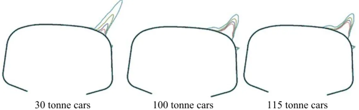
The direct impact of wheel load is illustrated by a pummelling simulation [11] in Figure 4 where an accumulation of Ekberg’s damage index [12] for empty freight cars is compared with the damage that arises from loaded cars. The damage has been scaled so that each plot refers to the same total tonnage of traffic. The four lines on each plot refer to different hardnesses, with the largest peaks corresponding to the lowest rail steel hardness. In all cases, the rail damage reduces as the rail hardness increases. Interestingly, for the empty car, RCF damage is noticeably greater on low hardness steels for the same accumulated tonnage. This is the result of contact stress not being strongly influenced by load (much more by profile, see Section 1.2) and the Ekberg RCF criterion depending much more on traction coefficient than stress, doubly negating the influence of wheel load. This is a good illustration of the complex interactions that occur at the wheel/rail contact, with loading from empty cars incurring more damage than the same tonnage of loaded axles, and with the damage during the empty condition being much more sensitive to rail hardness. The analysis also shows that for the same total tonnage, the RCF damage from 100 tonne cars is about the same as that from 115 tonne cars for all steel grades.
30 tonne cars 100 tonne cars 115 tonne cars Figure 4: Calculated rolling contact fatigue damage index on the RE141 rail for the same overall tonnage for cars of different weights, for rail hardnesses of 410, 380, 340 and 280 BHN. The rail damage reduces as the rail hardness increases.
1.2
Wheel/rail contact geometry
Any number of wheel/rail contact simulations readily illustrate that the key
parameter affecting contact stress is the transverse profiles of the wheel and rail (e.g. refs [11],[12],[13]). Those same profiles also govern steering performance in curves. Quasi-static curving simulations for four different wheel-rail profile combinations on a 700m radius curve at balanced elevation are illustrated in Figure 5. Each is annotated with the contact stress (Po in MPa), normal load (Pn in Newtons), the traction coefficient T/N, an index of frictional work (fricwk) and the Ekberg index for surface fatigue (s_rcf) for a premium rail steel. The 2-point contact scenarios are clearly associated with much higher overall wear rates, while the one point non-conformal is a higher stress condition than the one point non-conformal case. Generally
speaking, the practice is to aim for a one-point conformal on light axle load system and a two-point conformal under heavy axle loads.
Figure 5: Results of curving simulations for four different contact conditions illustrates the significant impact that profiles have on tractions and RCF damage. Friction values are 0.5 on the ball of the rail and 0.25 at the gauge corner.
1.3
Friction conditions
The Magic Wear Rate is primarily concerned with the early stage of crack propagation, i.e. first portion of Phase II in Figure 2, where there is a potential to manage cracks through wear. But the conceptual curve of Figure 2 is strongly influenced by friction. Figure 6 shows an example of the rate of crack propagation under different friction conditions inside the crack (µc) and at the wheel rail interface
(µs) [14]. It is noteworthy that RCF cracks propagate fastest under otherwise optimal
friction conditions (moderate top of rail, lubricated gage face) [15]. With increasing crack-face friction the rate of crack propagation slows down (µs = 0.4, µc = 0.4) with
much lower crack propagation rates at lower friction levels. This suggests why there has been mixed experience with lubrication and RCF; good friction management provides optimal conditions to prolong crack initiation rates but when lubrication is intermittent you can end up with a system of lubricated cracks and dry wheel-rail interface that contributes to disastrously high rates of crack propagation.
Figure 6: Crack growth rate curves from Reference [14].
Properly practiced, the introduction of top-of-rail (TOR) friction management reduces the development of RCF [1]. The role of friction management could be represented by a stretching of the RCF curve of Figure 3 to the right, so that the crack growth rate is slower and that more loading cycles (MGT) are required to initiate RCF cracks. With a best practice TOR friction coefficient of 0.3 to 0.4 and gauge face lubrication of <0.25 the RCF cracks will grow slowly. This was
demonstrated by Eadie et al [16] who through laboratory and field testing found that a thin film of friction modifier at the wheel/rail interface can significantly reduce both wear and RCF generation.
But there is another means by which the surface friction coefficient impacts crack growth. Lubrication of the outside rail, with the top of the inside rail being dry, dramatically increases lateral shearing forces on the inside rail (see Figure 7). This is due to the considerable reduction in steering moment that arises under lubrication, leading to higher wheelset yaw angles [17]. On the Canadian Pacific Railroad, 100% effective lubrication was associated with very high rates of wear on the crown of the low rail [18] and TOR friction management was required before both lateral forces and wear were controlled [19].
1.4
Tangential load at the wheel/rail contact
Axles that are misaligned with respect to curved or tangent track generate lateral and/or longitudinal tangential loads commensurate with the magnitude of angle of attack and rolling radius difference mismatch. Thus the specific conditions of axle misalignment, lateral loads on the cars, wheel diameters and presence or absence of lubrication and friction management can lead to tangential loads that vary from minimal to substantial and profoundly influence the growth of cracks. As seen in Figure 6, at the tangential loading of 10% of normal load (µs = 0.1) the rate of crack
propagation is very low. This might be the case under well matched wheel-rail profiles and a good flexible bogie on moderate radius curves.
Figure 7: Lubrication of the high rail gauge face causes a dramatic increase in lateral shear forces at the low rail [20].
The two most significant variables that influence the magnitude of tangential loads are track curvature, which generates angle of attack chiefly on the leading axles of bogies, and coefficient of friction which increases with the dryness of the rail. In sharp curves (radius less than 600 metres or curvature greater than 3 degrees) with angle of attack typically at or above six milliradians (i.e. 0.6% creepage) and dry rail friction, the shearing loads between wheel and rail can reach 60 – 70% of the normal load.
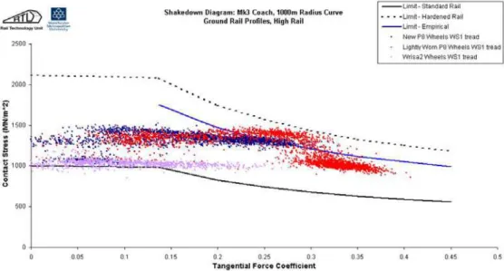
Matching of wheel and rail profiles affects steering performance which in turn has a strong effect on the tractive forces required to steer the wheelset through a curve. Work done by Iwiniki and his team [21] to evaluate the WRISA2 wheel profile proposed for the UK network found that when run over the same 1000m radius curve with the same vehicle, the proposed wheel roughly halved the average tangential force coefficient (see Figure 8) compared with the standard P8 wheel. Practical experience since has found reduced wear and RCF rates that enable a doubling of the retruing intervals for several fleets running that wheel [22]. The reduced wear and RCF on the wheel undoubtedly translates into reduced wear and RCF on the rail, and consequently a decrease in the Magic Wear Rate on that track.
Figure 8: A dynamic shakedown plot showing that for all other things being equal, the wheel profile can significantly affect not only the contact stress (vertical axis) but also the tangential force coefficient (horizontal axis). From Ref. [21].
Another parameter that has a strong effect on tangential forces is the track curvature. The calculated results of Figure 9 show that while wear number increases
consistently with degree curvature, the RCF index (Figure 10) saturates in the vicinity of 4 degrees on the outside rail. This is consistent with European experience where the fatigue/wear balance results in the highest RCF rates being at some intermediate curvature, with wear dominating at higher curvatures (Figure 11). But curiously, this is not the general experience in North America, where the sharpest curvatures have both the most severe gage face wear rates and most severe RCF. This is likely the result of profile changes that occur with the additional wear (and plastic flow) in sharper curves, leading to higher stress contact conditions on sharper curves. As well, over-balance running is much less prevalent in North America, and low rail damage a greater concern.
Figure 9: The wear numbers increase steadily with curvature for inside and outside rails.
Figure 10: The accumulated RCF for the same profiles and traffic (balanced speed, TOR=GF=0.4). The RCF index peaks at around four degrees for the
outside rail (left), but increases steadily on the inside rail (right).
1.5
Rail steel
Under identical service and rail loading conditions, the mechanical properties, cleanliness and microstructure of rail steel significantly influence its natural wear and crack propagation rates and consequently the artificial wear portion of MWR. As a general rule, the resistance to wear and crack propagation increases with increasing strength and hardness. Over the years rail manufacturers have achieved significant improvements in strength and hardness through a combination of alloying and various heat treatment procedures. Significant improvements in rail cleanliness have also been achieved in all grades and so cleanliness is rarely an issue in crack propagation rates. Although most rails are produced with pearlitic micro-structure, including 0.9 and 1.0%C hyper-eutectoid rails, bainitic microstructures are being extensively researched and tested (e.g. [23]) with some of the bainitic rails available on the market.
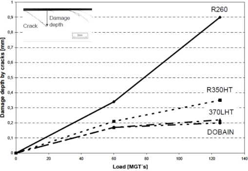
Cracks propagate to much lesser depth in high-strength premium rails as compared to 260BHN (R260) rail. Figure 12 demonstrates “the harder the better” trend with respect to crack propagation. Based on crack depth, steel grades R350HT (350 – 390BHN) and 370LHT (BHN > 370) suffer 67% and 87% less damage than R260 (260 – 300BNH), respectively. The bainitic rail DOBAIN (380 – 420BHN), showed crack growth rates similar to pearlitic rail 370LHT.
Figure 11: European experience is that there is a trade-off between RCF and wear, with RCF rates being greatest at some intermediate track curvature [23].
Figure 12: Depth of cracks in different rail steels subject to the same service interval (125MGT) and loading conditions (from Ref. [24])
Resistance to side wear on the outer rail, even with lubrication, increases
appreciably with rail hardness. Ref. [25] reports on a six-fold increase in gage-face wear resistance between 360 and 260 BHN rail steels, with rates reducing further still with harder steels. At the top of rail the reduction in wear rates on account of
increased hardness are not as dramatic. The wheel flange rubs (slips) on the side of the rail, but at the top of the rail there is strong rolling component and much less rubbing, resulting in a lower top of rail wear rate, a different wear mechanism, and a less pronounced hard rail to soft rail difference in wear reduction, about up to two- to three-fold [26] and even less with TOR friction management [27].
Since the resistance to wear, crack propagation and plastic flow increases with hardness, the associated reductions in crack depth and profile change with time in turn minimize the needed frequency and depth of grinding interventions, thereby reducing the magic wear rate and increasing rail life. This is illustrated in Figure 13. Similar lines can be plotted to illustrate the effects of friction management, rail curvature and improved wheel/rail profiles.
Figure 13: Comparison of magic wear rate for premium (≈390BHN) and standard (≈260BHN) rails.
Since both wear and the rate of crack growth increase with curvature, while resistance to both increases with hardness, it is common practice to place hard grades of rail into the sharp curves and high tonnage track. The preference for linking the rail grade (i.e. hardness) to track tonnage/curvature varies across the railway administrations but they all show a trend of placing increasingly harder rails into sharper curves. Some railroads prefer three grades; standard (≈260BHN) intermediate (≈330 BHN) and premium (≈390BHN), while others apply only two grades; intermediate (≈330 BHN) in tangent and mild curves and premium
(≈390BHN) in sharp curves. Such strategies increase rail life, reduce the demand on rail grinding and help the grinding programs to manage metal removal rates to approach the desired magic wear rate for each tonnage/curvature segment of track.
2
Examples of current practices
In a typical system, the natural wear that occurs between the wheel and rail during regular service is not enough, nor has the wear the right distribution across the rail, to prevent rolling contact fatigue from developing. As the naturally worn wheel and rail profiles shown in Figure 14 illustrate, the shapes wear non-uniformly and so the contact conditions vary throughout their life and between maintenance intervals. While one might assume that the shapes will wear to a low stress condition, experience proves otherwise, with wheels typically wearing to a higher conicity shape and rails wearing flatter with a sharper gauge corner. The result is that in virtually all cases of natural wear and plastic flow, the outside rail suffers a concentrated band of rolling contact fatigue on the gauge corner.
a) wheel wear from 0 to 12740 miles b) two different cycles of natural wear on a rail.
Figure 14: Examples of typical worn A) wheel and B) rail shapes.
Unfavorable wheel/rail contact conditions can lead to significant deterioration in wheel/rail performance such as high rates of fatigue, instability at higher speeds, noise and sometimes derailment. The role of rail grinding is two-fold: to remove fatigue and to restore favourable rail shapes. Then the question becomes: “when is the optimal time to grind and what is the optimal grinding cycle in terms of MGT”? Rail grinding was introduced in North America in the 1980’s chiefly to treat severe rail corrugation. As rail steels have improved along with grinder productivity, rail corrugation has effectively been eliminated as the reason for rail grinding on heavy
freight railroads. Instead, grinding is performed to manage shape and rolling contact fatigue.
There are several different approaches to rail grinding as detailed in Ref. [28] with a numerical comparison shown in shown in Table 1.
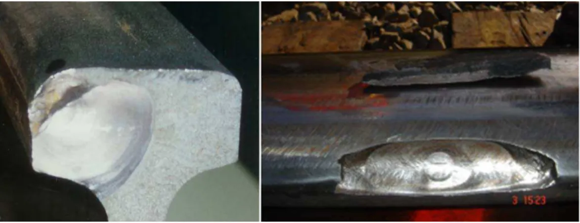
Corrective or reactive grinding treats rail that has been heavily damaged and requires large quantities of material removal through typically 5 or more passes at a slow speed (5-9 km/hr) using a large production rail grinder. Even with heavy metal removal, cracks typically still remain in the rail (e.g. Figure 15). The post-grind material is thus already weakened and the profile deteriorates rapidly, so performance is poor for a large portion of the service life and the overall life is low. The corrective grinding interval might be 100 MGT or more.
Figure 15: Even after 3 passes with a production grinder and more than 44.5 mm sq (0.069 in sq) of metal removal, cracks still remained in this rail [29]. Maintenance grinding treats the rail more frequently, taking fewer passes each
time (around 3-5 with a high production rail grinder). The maintenance grinding interval on sharp curves might be around 40-80 MGT.
Preventive grinding typically takes only a single pass with a high production rail grinder but does so more frequently at an interval of 15-35 MGT on sharp curves. Often the grinder is able to work at higher speeds (14-20 km/hr) and in the forward direction only, avoiding inefficiencies associated with direction changes and motor carriage movements, thus greatly improving productivity. The number of track miles covered per day is high, disruption to traffic can be much lower, the rail shape is regularly maintained for optimal wheel/rail contact conditions, and deeper rolling contact fatigue cracks never gets a chance to infect the rail. This is the safest regime – with defects minimized ([1],[30]) and
Table 1: Comparison of performance under various rail grinding approaches in sharp curves in 127 MGT territory for the low rail [1].
Typical values for: Corrective Maintenance Preventive
Grinding interval (MGT) 60 30 15
Grinding speed (kph) 10 10 10
Grinding passes per cycle 9 5 1
Total passes per 127 MGT 18 20 8
Rail Wear (mm per 127 MGT) 6.25 9.4 5.8
Expected life (MGT)* 465 339 549
Grinding cost ratio 1.85 2.52 1
*Rail maintained at corrective and maintenance grinding intervals is replaced at a head loss of 25%. Rail maintained at preventive grinding intervals is replaced at 35 to 40% head loss [31]
There was some controversy in the late 90’s when test results published in the USA suggested that premium rail required little or a “no-grind” approach ([32],[33],[34]). Preventive rail grinding was reported to increase rail wear by 77% on the high rail and 240% on the low rail and that removing rail spalls by grinding reduced rail life by 50%. It was also reported that premium steels in curves in dry environments can successfully withstand several hundred MGT without grinding. This naturally led railroad executives to ask “why are we grinding then?” With the passage of addition-al time the rail eventuaddition-ally failed due to rolling contact fatigue. For example, in tests where sharp curves were not ground [1] the rail failed ultrasonic tests at 300 MGT and had to be either removed from service or correctively ground to achieve success-ful ultrasonic tests. With gauge face lubrication, TOR and preventive grinding the rail head area lost per MGT is lower and the metal removal by grinding reduced (by 3.5 times) compared to using corrective grinding [29]. Through the preventive rail grinding practice, railroads such as the Canadian Pacific [29] and Burlington North-ern Santa Fe [1] have realized significant gains in grinding productivity, extended rail life and improved safety by dramatically reducing the rate of internal defects [34]. Current single-pass preventive grinding intervals are summarized in Table 2. Table 2: Current best practice single-pass preventive grinding intervals [35].
Curvature Rail Grade Preventive Grinding Interval Sharp Premium 14 - 23 (15-25MGT)
Mild Premium 27 - 45 (30-50 MGT) Tangent Intermediate 40 - 54 (45-60MGT)
Tangent Premium 91 (100MGT)
High Speed Grinding [36] is another preventive approach wherein very small amounts of metal are removed very frequently using a machine the travels at speeds of up to 80 km/hr. While this approach represent a strong application of the MWR principle, the limited ability to profile the rail to different shapes in curves and tangent means that it is unlikely to completely replace other forms of rail grinding that will usually be needed for restoring optimised rail shapes.
3
Identifying the Magic Wear Rate
Although the concept of artificially increasing wear to control RCF is commonly applied to maintain both rail and wheel, it is fair to say that only rarely is the Magic Wear Rate being achieved. In nearly all cases where machining operations are used to control and/or remove RCF, the artificial wear rate far exceeds the Magic Wear Rate, resulting in lower life, less efficiency and excessive disruption to service than the potential optimum. But identifying the Magic Wear Rate at any location of track remains a difficult goal. Through the proper application of existing and new
technologies we are getting ever closer to being able to determine the rate of metal removal required to control RCF and achieve the longest rail life.
Currently, rail grinding quality is evaluated according to the shape of the rail profile left behind – a profile quality index. The in-track profile is measured using a laser systems and the difference from the target optimal rail profile calculated. This process is performed either on-board the grinding machine or using a specialized pre-grind rail inspection vehicle (e.g. [37],[38]). In some cases the software system can also recommend the number of grinding passes, the grinding speed and required grinding pressure on the motors to produce the profile. A vision system on board the grinder or rail inspection vehicle records a high resolution digital image of the rail surface and the RCF present, for example every two meters at an inspection speed of 15-50 km/h. These images are then reviewed by a trained operator and depending on the severity of damage, extra metal can be prescribed for removal by indexing the template downwards [39]. The problems with this approach for assessing the preventive grinding requirements according to references [29] and [40] are:
Visual assessment of RCF severity from digital images is subjective, Estimating the depth to index the template into the rail will likely remove
too much or too little metal from the rail, and
There is no follow-up to know whether the grind was a success or failure.
3.1
Predictive Preventive Grinding
The best grinding approach takes place at the tonnage interval defined by the Magic Wear Rate for each track curvature. This will benefit the railroad on two important levels: removing just enough metal each grinding cycle to maximise rail life, and; planning of the rail grinding based on an optimised return on investment (ROI) for each section of track.
The National Research Council of Canada (NRC) developed a generic RCF crack propagation curve similar to that of Figure 3 for heavy haul track and calibrated the curve for the BNSF Railway for each degree of curvature from 3492 to 269 meter radius (0.5 to 6.5 degrees) and each rail position (tangent, high or low rail). The calibration was based on wheel wear and rail grinding rates extracted from six years
of track geometry car and historical rail grinding data for two high curvature subdivisions [29].
The predictive preventive grinding (PPG) methodology was developed that applies an ROI model and railway specific data to plan the grinding based on predicted metal removal needed to remove RCF for various combinations of MGT, track curvature, rail position (high / low / tangent), state of lubrication, grinder metal removal rates, rail grade, rail size, and others [29]. The ROI analysis determines the ideal preventive grinding interval that maximizes rail life subject to rail replacement and rail grinding costs.
The new predictive preventive grinding model, in comparison with the traditional approach to preventive grinding as used on BNSF Railway, theoretically saves between 5 and 7.4 million US dollars over 10 years in rail and maintenance costs for one subdivision alone [29]. The new grinding strategy is predicted to extend rail life a further 22% to 58% through improved grinding efficiencies.
Implementation of the predictive preventive grinding strategy still needs further development since the validation methodology is very time consuming and labour intensive. An accurate and easy to use method to monitor crack depths would be extremely useful for determining crack growth rates. There are commercially available, automated tools, to measure the depth of the RCF on rail bound machines in Europe (e.g. [38]), but measuring crack depth on heavy haul railways is difficult with these and their walking stick counterparts because of the complexity involved in interpreting the signal. There is a sensitivity issue and corruption from other surface discontinuities; hence directly measuring the crack depth remains difficult [41].
But even once the Magic Wear Rate is known for a given section of track, there remains the challenge of practically implementing it.
4
Implementation Strategy
For rail that has heavy RCF at the outset, a transitioning process is required. The preventive gradual [1] and predictive-preventive [29] grinding approaches have been developed for this purpose. But once the rail surface is “clean” a MWR preventive grinding approach can be followed.
While rail profile quality is assessed using the profile quality index, it has been proposed in Ref. [40] that an Equivalent Grinding Index (EGI) be developed for determining the MWR through optimisation of 3 weighting factors – profile quality, RCF condition and the grinding interval. RCF growth rates would be assessed using crack measurement technology and grinding interval would be predicted based on the ROI analysis of the optimal and economic timing for grinding each location. Such an index directly addresses the variables that are most critical in getting close to the MWR:
the accuracy of the shape of ground rail profile – achieving the target profile leads to reduced contact stresses and lower crack propagation rates,
knowledge of actual depth of RCF cracks in various segments of the track, and
the desired tonnage interval (mgt or MGT) at which the bulk of the cracks would be removed by one grinding pass.
The EGI will maximize rail life as well as optimise rail replacement and rail grinding costs.
Rail grinding plans would depend on a calculation of the MWR for all segments of track in a specific railway territory. The rail grinder would circulate over the
territory on the calculated optimum grinding cycle and each track segment (based on the distribution of tangent or curve high rail or low rail and their RCF curves) is either skipped, ground with one pass or multiple passes (with a controlled
preventive-gradual grinding strategy) based on metal removal needed to remove or control RCF. Some locations would be at the optimal MWR and others would be ground with the metal removal that is needed to address the depth of the RCF depending on position on the RCF curve for each specific location. Some rail may have more severe RCF growth rates (e.g. due to poor geometry) compared to other typical rail of the same curvature in the territory. These will then need to be addressed on a curve by curve basis. Data to support the development and
implementation of the EQI is being gathered through measurement of RCF in heavy haul railways and will be published at a later date.
5
Conclusions
The Magic Wear Rate is the rate of wear at which any rolling contact fatigue cracks that are in initial stages of development are removed either by natural or
combination of natural and artificial wear. Although in theory one could introduce higher wearing material to combat RCF, the fact is that natural wear is not normally sufficient to remove RCF in all cases, and since it is not distributed evenly across the running surface, the shape changes over time. Artificial wear then is required and through deliberate intervention by maintenance forces using grinding or milling, the contact shapes can be corrected and RCF removed.
The amount of metal that must be removed to control RCF depends on the rates of crack initiation and propagation, which in turn are highly dependent on the operating conditions, including axle load, wheel/rail profiles, track geometry and friction management practices. Rail curvature plays a strong role with wear steadily increasing with curvature and RCF also increasing steadily on the low rail. But contrary to expectation, RCF is modeled to plateau at around 4 degrees on the high rail - further work is needed to explore this phenomenon. Friction management has a very strong influence on both wear and RCF and has been demonstrated in both lab
and field testing to dramatically increase the time to RCF development and thereby reduce the Magic Wear Rate.
Material properties also have a very strong impact. Premium steels (e.g. BHN380) have a Magic Wear Rate that is roughly 1/3rd that of “Standard” metallurgies at 260-280BHN. Modern high hardness bainitic steels promise to reduce that value even more.
In practice, the Magic Wear Rate is also affected by the machining approach used to supplement natural wear. To obtain the most effective use of a vertical spindle grinder the best practice is to grind at a frequency that requires the grinder to remove the maximum amount of metal that it can in a single pass. So for less powerful machines, a single pass of grinding may require it to return at a shorter cycle, which counter-intuitively could call for it to remove a total lower amount of metal than a more powerful grinder. But the tradeoff in grinding costs and reduction in service disruption still tends to favor more powerful grinders. In optimizing grinding for the Magic Wear Rate, it has been proposed that an equivalent grinding index (EGI) be developed that considers profile quality, severity of existing RCF and the grinding interval. The optimal value is determined based on an ROI analysis that minimizes overall costs for a given territory. Work to better understand and apply the EGI is ongoing.
References
[1] J. Stanford, E. Magel, and P. Sroba, “Transitioning from corrective to preventive rail grinding on the BNSF Railroad”, Proceedings IHHA Conference, Perth, Australia, June 2001.
[2] J. Baillargeon, D. Gutscher and D. Li, “Premium rail performance and rail life extension under heavy axle load revenue service environments”, Railway Track and Structures, October 2013.
[3] P. Sroba et al, “The Evolution of Rail Grinding on Canadian Pacific Railway to Address Deep Seated Shells in 100% Effective Lubrication Territories”, Proceedings World Congress on Railway Research, Montreal, Canada, June 2006.
[4] Office of Rail Regulation, “Train derailment at Hatfield: a final report by the Independent Investigation Board”, July 2006
[5] J. Kalousek and E. Magel, “The “Magic” Wear Rate”, Railway Track and
Structures, March 1997
[6] K.L. Johnson and J.A. Jefferis, "Plastic Flow and Residual Stresses in Rolling and Sliding Contact", Proc. Symposium Fatigue in Rolling Contact, London, UK, 1963
[7] A. Kapoor, F. Schmidt, D. Fletcher, “Managing the critical wheel-rail interface”, Railway Gazette International, 2002
[8] H. Harrison, L. Chang and W. GeMeiner, “Managing the gross weight on rail”, Proceedings Joint Rail Conference, Atlanta, USA, April, 2006
[9] Y.Q. Sun, M. Dhaneskar and D. Roach, “Wheel-rail interaction responses due to track geometry irregularities”, Proceedings of the International Conference and Exhibition Railway Engineering, London, UK, 30 April - 1 May 2003 [10] S. Cumming et al, “Measurement of wheel/rail load environment in relation to
rolling contact fatigue”, Proceedings Joint Rail Research Conference, Colorado, USA, March 2011
[11] E. Magel and J. Kalousek, “The application of contact mechanics to rail profile design and rail grinding”, Wear, Vol. 253, 2002, pp. 308-316 [12] A. Ekberg and E. Kabo, “Fatigue of railway wheels and rails under rolling
contact and thermal loading—an overview”, Wear, Vol. 258, Issues 7–8, March 2005, pp. 1288-1300
[13] I.Y. Shevtsov, V.L.Markine, C.Esveld, “Design of railway wheel profile taking into account rolling contact fatigue and wear”, Wear, Vol. 265, 2008, pp. 1273-1282
[14] X. Xu et al, “Evaluation of slant crack propagation under RCF in railway rail”, Journal or Mechanical Science and Technology 25 (50), 2011, pp. 1215-1220
[15] J. Kalousek and E. Magel, “Modifying and managing friction”, Railway Track
and Structures, May 1997.
[16] D.T. Eadie et al, “The effects of top of rail friction modifier on wear and rolling contact fatigue: Full-scale rail–wheel test rig evaluation, analysis and modelling”, Wear, Vol. 265, 2008, pp. 1222-1230
[17] G. Izbinsky et al, “Monitoring bogie performance on straight track. Part 1. Wheel set tracking position”, Proceedings World Conference on Railway Research, 2006
[18] P. Sroba et al, “Canadian Pacific Railway’s 100% Effective Lubrication Initiative”, Proceedings AREMA Conference, Chicago, USA, September 2001
[19] P. Sroba et al, "Canadian Pacific Railway 100% Effective Friction Management Strategy”, Proceedings IHHA Conference, Rio de Janeiro, Brazil, 2005.
[20] P. Sroba, E. Magel, and R. Caldwell, “Testing of Rail Friction Management on the 377.2 Baltimore Curve”, NRC report #54-A62209-T11-2-AUG05, August 2005
[21] NRC Canada, “Final Report RSSB 1067 – Study to develop an Anti-RCF wheel profile”, June 2004.
[22] M. Burstow, “Experience of the P12 profiles”, presentation to VT/SIC PPG October 23, 2012
[23] G. Girsch, N. Frank, P. Pointner, “New rail grades—a technical performance overview”, Proceedings IHHA Conference, Rio de Janeiro, Brazil, 2005, pp. 731–738.
[24] G. Girsch et al, “Life cycle cost considerations on high strength rail steels”, Proceedings WCRR, 2008
[25] J. Kalousek, "Wear and Contact Fatigue Model for Railway Rail", NRC Technical Report, TR-WE-50, NRC No. 27491, TDC No. TP8344E, 1986
[26] P. Pointner, “High Strength Rail Steels – The Importance of Material
Properties in Contact Mechanics Problems”, Proceedings Contact Mechanics and Wear of Rail/Wheel Systems, Brisbane, Australia, 2006
[27] DT. Eadie et al., "Top of rail friction control: lateral force and rail wear reduction in a freight application", Proceedings IHHA Conference, Dallas, USA, 2003, pp. 5-9
[28] E. Magel et al, “Control of Rolling Contact Fatigue of Rails”, Proceedings of AREMA Conference, Nashville, USA, September 2004
[29] P. Sroba, R. Caldwell, R. Harris, “Predictive Preventive Grinding to Control Rolling Contact Fatigue in Rails Is Implemented on Burlington Northern Santa Fe Railroad”, Proceedings IHHA Conference, Calgary, Canada, June 2011.
[30] R. DeVries, P. Sroba, E. Magel, “Preventive Grinding Moves into the 21st Century on Canadian Pacific Railway”, Proceedings AREMA Conference, Chicago, USA, September 2001.
[31] Guidelines to best practice for Heavy Haul Railway Operations Wheel and Rail Interface Issues, International Heavy Haul Association, 2001
[32] J. Hannafious , “Rail Profile Grinding Philosophies and Practices of Four US Railroads”, TTCI Technology Digest #94-010
[33] R.E. Tuzik, “To Grind or not to Grind”, Railway Track and Structures, March 1996.
[34] K. Sawley, “TTCI tests measure relation between grinding, rail life”, Railway Track and Structures, June 1999.
[35] Guidelines to best practice for Heavy Haul Railway Operations, Infrastructure Construction Maintenance Issues, International Heavy Haul Association, 2009
[36]
http://www.vossloh-usa.com/media/downloads/pdfs/1_High_Speed_Grinding_by_VRS_USA.pdf [37] R. Harris. “Man versus Machine, testing Automated rail Grinding
Pre-Inspection vs manual Methods”, Proceedings IHHA Conference, New Delhi, India 2013
[38] W. Schoech, “Recording Assisted RCF-Treatment gains Ground”, Proceedings IHHA Conference, New Delhi, India, February 2013
[39] M. Turner, “Rail maintenance improvements through capital investment and technological advancements”, Proceedings IHHA Conference, Calgary, Canada, June 2011.
[40] P. Sroba et al, “Rail Grinding Quality Assurance Based on Profile Correction and RCF Control”, Proceedings CORE Conference, Wellington, NZ,
September 2010.
[41] D. Raman, “RCF Quantification - Towards Rail Grinding Best Practices for Australian Heavy Haul Rail”, Proceedings World Congress on Railway Research, Sydney, Australia, December 2013.
![Figure 2: Three stages of contact fatigue crack growth (Ref. [7])](https://thumb-eu.123doks.com/thumbv2/123doknet/14104494.465956/4.918.274.643.517.696/figure-stages-contact-fatigue-crack-growth-ref.webp)


![Figure 6: Crack growth rate curves from Reference [14].](https://thumb-eu.123doks.com/thumbv2/123doknet/14104494.465956/8.918.283.634.143.403/figure-crack-growth-rate-curves-reference.webp)
![Figure 7: Lubrication of the high rail gauge face causes a dramatic increase in lateral shear forces at the low rail [20]](https://thumb-eu.123doks.com/thumbv2/123doknet/14104494.465956/9.918.193.704.142.525/figure-lubrication-gauge-causes-dramatic-increase-lateral-forces.webp)