Publisher’s version / Version de l'éditeur:
Vous avez des questions? Nous pouvons vous aider. Pour communiquer directement avec un auteur, consultez la
première page de la revue dans laquelle son article a été publié afin de trouver ses coordonnées. Si vous n’arrivez pas à les repérer, communiquez avec nous à [email protected].
Questions? Contact the NRC Publications Archive team at
[email protected]. If you wish to email the authors directly, please see the first page of the publication for their contact information.
https://publications-cnrc.canada.ca/fra/droits
L’accès à ce site Web et l’utilisation de son contenu sont assujettis aux conditions présentées dans le site LISEZ CES CONDITIONS ATTENTIVEMENT AVANT D’UTILISER CE SITE WEB.
Technical Report (National Research Council of Canada. Institute for Ocean Technology); no. TR-2006-10, 2006
READ THESE TERMS AND CONDITIONS CAREFULLY BEFORE USING THIS WEBSITE.
https://nrc-publications.canada.ca/eng/copyright
NRC Publications Archive Record / Notice des Archives des publications du CNRC :
https://nrc-publications.canada.ca/eng/view/object/?id=6d673494-97ef-487b-b888-b7cd70b31018 https://publications-cnrc.canada.ca/fra/voir/objet/?id=6d673494-97ef-487b-b888-b7cd70b31018
NRC Publications Archive
Archives des publications du CNRC
For the publisher’s version, please access the DOI link below./ Pour consulter la version de l’éditeur, utilisez le lien DOI ci-dessous.
https://doi.org/10.4224/8896209
Access and use of this website and the material on it are subject to the Terms and Conditions set forth at
Description of propeller open water experiments carried out on warship propellers IOT 319L/R
REPORT NUMBER
TR-2006-10
NRC REPORT NUMBER DATE
April 2006
REPORT SECURITY CLASSIFICATION
UNCLASSIFIED
DISTRIBUTION
UNLIMITED
TITLE
DESCRIPTION OF PROPELLER OPEN WATER EXPERIMENTS CARRIED OUT ON WARSHIP PROPELLERS IOT319L/R
AUTHOR(S)
D. Cumming, R. Pallard
CORPORATE AUTHOR(S)/PERFORMING AGENCY(S)
IOT
PUBLICATION
N/A
SPONSORING AGENCY(S)
Dept. of National Defence
IOT PROJECT NUMBER
42_2104_16
NRC FILE NUMBER KEY WORDS
Propellers, open water
PAGES vi, 6, App. A-G FIGS. 2 TABLES 2 SUMMARY
This report describes propeller open water experiments carried out on a pair of stock Institute for Ocean Technology (IOT) five bladed warship propellers, designated IOT319L/R, in the IOT Tow Tank January 13, 2006. These propeller are normally fitted to a large scale warship model such as HALIFAX Class frigate model IOT691.
ADDRESS National Research Council
Institute for Ocean Technology Arctic Avenue, P. O. Box 12093 St. John's, NL A1B 3T5
National Research Council Conseil national de recherches Canada Canada Institute for Ocean Institut des technologies
Technology océaniques
DESCRIPTION OF PROPELLER OPEN WATER EXPERIMENTS
CARRIED OUT ON WARSHIP PROPELLERS IOT319L/R
TR-2006-10
D. Cumming, R. Pallard
LIST OF TABLES Table List if Signals ... 1 Repeat Runs ... 2 LIST OF FIGURES Figure
Schematic of IOT Propeller Open Water Dynamometer... 1 Photograph of Propellers IOT319L/R and Fittings... 2
TR-2006-10
LIST OF ABBREVIATIONS
DC direct current deg. degree(s)
deg. C, °C degree(s) Centigrade CCW counter clockwise
CW clockwise
GDAC General Data Acquisition and Control GEDAP General Data Analysis Package
Hz Hertz
IOT Institute for Ocean Technology (formerly Institute for Marine Dynamics) kg kilogram(s)
K&R Kempf & Remmers
kW kiloWatt(s)
m metre(s) mm millimetre(s)
MARIN Maritime Research Institute Netherlands N Newton(s)
P/D pitch/diameter QA quality assurance rps revolution(s) per second t tonne(s)
T1, T2 start, end times
LIST OF SYMBOLS – PROPELLER OPEN WATER EXPERIMENTS1
Symbol Definition
υ M kinematic viscosity of the water in the test facility, m 2/s ρM density of the water in the test facility, kg/m
3 ηO open efficiency
c0.7 model propeller blade cord at 0.7 radius, m D model propeller diameter, m
Fr Froude number for the ship and model
g gravitational acceleration (standard IOT value 9.808 m/s2 ) JO advance coefficient in propeller open water test
KQO propeller torque coefficient in open water test KTO propeller thrust coefficient in open water test KTDO duct thrust coefficient in open water test nO propeller rate of rotation in open water test, rps QO propeller torque in open water test, Nm
Rnco propeller Reynolds number
TO propeller thrust in open water test, N TDO duct thrust in open water test, N
VA propeller speed of advance in open water test, m/s
1 Note IOT uses ITTC Symbols Version 2002.
TR-2006-10
TABLE OF CONTENTS
List of Tables ... iv
List of Figures ... iv
List of Abbreviations ... v
List of Symbols (Propeller Open Water Experiments) ... vi
1.0 INTRODUCTION ... 1
2.0 DESCRIPTION OF THE IOT TOWING TANK... 1
3.0 DESCRIPTION OF IOT PROPELLER OPEN WATER DYNAMOMETER ... 1
4.0 DESCRIPTION OF PROPELLERS IOT319L/R... 1
5.0 DESCRIPTION OF INSTRUMENTATION AND DATA ACQUISITION SYSTEM... 2
6.0 CALIBRATION PROCEDURE... 2
7.0 TEST PROGRAM ... 3
8.0 DATA ANALYSIS PROCEDURE... 3
9.0 DATA QUALITY CONTROL... 5
10.0 ACKNOWLEDGEMENTS... 6
11.0 REFERENCES ... 6 APPENDIX A: Description of IOT Towing Tank
APPENDIX B: QA Information for Propellers IOT319L/R APPENDIX C: Instrumentation Calibration Results
APPENDIX D: Test Program APPENDIX E: Run Log
APPENDIX F: Online Data Analysis Results APPENDIX G: Offline Data Analysis Results
LIST OF TABLES Table List of Signals ... 1 Repeat Runs ... 2 LIST OF FIGURES Figure
Schematic of IOT Propeller Open Water Dynamometer... 1 Photograph of Propellers IOT319L/R and Fittings... 2
TR-2006-10
LIST OF ABBREVIATIONS
DC direct current deg. degree(s)
deg. C, °C degree(s) Centigrade CCW counter clockwise
CW clockwise
GDAC General Data Acquisition and Control GEDAP General Data Analysis Package
Hz Hertz
IOT Institute for Ocean Technology (formerly Institute for Marine Dynamics) kg kilogram(s)
K&R Kempf & Remmers
kW kiloWatt(s)
m metre(s) mm millimetre(s)
MARIN Maritime Research Institute Netherlands N Newton(s)
P/D pitch/diameter QA quality assurance rps revolution(s) per second t tonne(s)
T1, T2 start, end times
LIST OF SYMBOLS – PROPELLER OPEN WATER EXPERIMENTS1
Symbol Definition
υ M kinematic viscosity of the water in the test facility, m 2/s ρM density of the water in the test facility, kg/m
3 ηO open efficiency
c0.7 model propeller blade cord at 0.7 radius, m D model propeller diameter, m
Fr Froude number for the ship and model
g gravitational acceleration (standard IOT value 9.808 m/s2 ) JO advance coefficient in propeller open water test
KQO propeller torque coefficient in open water test KTO propeller thrust coefficient in open water test KTDO duct thrust coefficient in open water test nO propeller rate of rotation in open water test, rps QO propeller torque in open water test, Nm
Rnco propeller Reynolds number
TO propeller thrust in open water test, N TDO duct thrust in open water test, N
VA propeller speed of advance in open water test, m/s
1 Note IOT uses ITTC Symbols Version 2002.
TR-2006-10
DESCRIPTION OF PROPELLER OPEN WATER EXPERIMENTS CARRIED OUT ON WARSHIP PROPELLERS IOT319L/R
1.0 INTRODUCTION
This report describes propeller open water experiments carried out on a pair of stock Institute for Ocean Technology (IOT) five bladed warship propellers, designated
IOT319L/R, in the IOT Tow Tank January 13, 2006. These propellers are normally fitted to a large scale warship model such as HALIFAX Class frigate model IOT691.
2.0 DESCRIPTION OF THE IOT TOWING TANK
The IOT Towing Tank has dimensions of 200 m by 12 m by 7 m with a dual-flap wavemaker fitted at one end capable of generating uni-directional regular waves up to 1 m in height or irregular waves up to a 0.5 m significant wave height. A wave absorber consisting of a parabolic beach is fitted at the opposite end. Flexible side absorbers can also be deployed along the entire length of the tank to minimize the time between runs. The 80 t tow carriage capable of speeds up to 10 m/s is used to accommodate models for a wide range of test types carried out in calm water or waves. A 4,000 kg lift capacity moveable overhead crane is available over most of the tank length. Additional
information on the Towing Tank is provided in Appendix A.
3.0 DESCRIPTION OF IOT PROPELLER OPEN WATER DYNAMOMETER
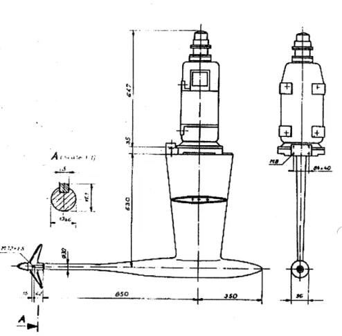
The IOT propeller open water dynamometer is used to determine the characteristics of model propellers in a homogeneous flow field and can be mounted in either the 200 m Towing Tank or Cavitation Tunnel. The IOT unit is a model H-39, fabricated by Cussons Technology Marine Research Systems Division in the U.K. Torque and thrust of the propeller are measured using separate full-bridge strain gage transducers in a streamlined body, which is an extension of the propeller shaft. The strain gages are temperature compensated and an effort has been made to minimize crosstalk. A schematic of the dynamometer is presented in Figure 1.
Rated Torque = ± 55 N-m Rated Thrust = 1000 N
Maximum Shaft Speed = 50 rps
Power of the Drive Motor for Rated Torque @ 50 rps = 18 kW
4.0 DESCRIPTION OF PROPELLERS IOT319L/R
The propellers designated IOT319L/R are nominally 320.4 mm diameter 5 bladed adjustable pitch warship propellers fabricated by the Maritime Research Institute
Netherlands (MARIN) several years ago. The MARIN designation for these propellers is 5687L/R and when received by IOT were is rather poor condition. The propeller hubs were bored out and a sleeve inserted such that they could be accommodated on the IOT
standard shaft diameter. The propellers were then set by IOT at the nominal design pitch of 31.012 degrees (P/D = 1.322). The QA information for these propellers is provided in Appendix B while a photograph of the propellers along with associated fittings is given in Figure 2.
5.0 DESCRIPTION OF INSTRUMENTATION AND DATA ACQUISITION SYSTEM
The experiments were carried out using the standard IOT propeller open dynamometer fitted to the tow carriage in the IOT Towing Tank.
All acquired analog DC signals were low pass filtered at 10 Hz, amplified as required and digitized at 50 Hz using IOT’s standard data acquisition system and software described in Reference 1.
The signals measured and recorded during the propeller open water experiments are listed in the Table 1.
6.0 CALIBRATION PROCEDURE
The procedure used to calibrate each individual signal is described as follows using the standard IOT sign convention described in Reference 2.
Tow Carriage Speed: Carriage speed is calibrated periodically by setting up two proximity switches on the Towing Tank rails at a measured distance apart with
companion switches on the tow carriage linked by cable to the carriage data acquisition system. The tow carriage is operated at a constant speed between the two switches and the time between activating the switches recorded on the carriage data acquisition system – thus providing an accurate measure of tow carriage speed.
Shaft Speed: The shaft speed was measured using a pre-installed tachometer that provides an analog signal linearly proportional to shaft speed and was calibrated using a laser tachometer directed at a piece of reflective tape located on the drive shaft.
Shaft Thrust, Torque: In order to statically calibrate the propeller open water
dynamometer; the device is mounted to a dedicated K&R calibration jig. To calibrate the thrust, the dynamometer was mounted with the sensing end pointed upward with a
spreader bar and weight tray hanging from it. Static weights were added to the weight tray – 70 kg in total in 10 kg increments. To calibrate the torque, a lever arm with a weight tray mounted on one end, was mounted horizontally to the sensing end of the dynamometer. A torque clamp was added to the other end of the dynamometer to prevent the internal shaft from rotating. Static weights were added to the weight tray – 10 kg in 2 kg increments. The thrust was calibrated over a range of 0 to 700 N, while the torque was calibrated over a range of ± 50 N-m.
TR-2006-10 Instrumentation calibration results are presented in Appendix C.
7.0 TEST PROGRAM
The test program was carried out as per IOT’s standard propeller open water test
procedure (Reference 3). Due to the large size of the propellers, care was taken to ensure the loads on the propeller opens boat did not exceed maximum allowable values. The planned test program is provided in Appendix D. Shaft friction values were acquired with dummy hubs fitted at the beginning and end of testing for each propeller from 7 to 14 rps in 1 rps increments. The following three shaft speeds were planned:
For no = 8 rps – Rnco corresponds to 476747.
For no = 11 rps – Rnco corresponds to 655527.
For no = 13 rps – Rnco corresponds to 774713.
Due to excessive shaft vibration noted at bollard at a shaft speed of ~ 7.5 rps, it was decided to carry out experiments at 7 rps and 11 rps only – although it was necessary to omit low Jo values for the 11 rps speed. A Run Log for experiments carried out on both
propellers is given in Appendix E.
8.0 DATA ANALYSIS PROCEDURE
The data were acquired in GDAC format (*.DAC files) described in References 4, 5. The data were converted to GEDAP format described in Reference 6 prior to carrying out an online data analysis on the Tow Tank carriage workstation during the test to verify the integrity of the acquired data. The online data analysis for each propeller is described as follows:
Online data analysis for each shaft friction run:
• The shaft torque and shaft speed were plotted on the screen in the time domain. Start and end times (T1, T2) are interactively selected for each steady state segment.
• Basic statistics (minimum, maximum, mean, standard deviation) were computed for each data segment.
• A plot of mean shaft torque vs. shaft speed was now displayed on the screen and the user required to interactively fit a spline curve through the data.
• A spline curve of mean shaft torque vs. shaft speed was now output to a GEDAP file.
Propeller open water data for 198.12 mm diameter 5 bladed adjustable pitch warship propellers IOT131 L/R (former MARIN propellers 4055L/R) acquired as described in Reference 7 was used as a source for the comparison curves (KTO vs. JO) and (10KQO vs.
JO) for the online analysis where:
D n V J O A O = (1) 5 2 D n Q K O M O QO ρ = (2) 4 2 D n T K O TO ρ = O M (3) Online data analysis for each propeller open water run:
• The shaft torque, shaft thrust, shaft speed and carriage speed are plotted on the screen in the time domain. Start and end times (T1, T2) are interactively selected for the tare segment as well as for each steady state segment. There was more than one steady state segment if more than one forward speed was acquired during a single run up the tank – a common situation for low forward speeds. • Basic statistics (minimum, maximum, mean, standard deviation) were computed
for each data segment.
• A routine was executed where the nondimensional propeller coefficients:
advance coefficient, JO, torque coefficient, KQO, and thrust coefficient, KTO, were computed using the corrected averaged values of each relevant parameter. These dimensionless coefficients are calculated using equations 1 to 3 and mean values as well as dimensionless coefficients are output to an ASCII point [.PNT] file. • A plot of the computed nondimensional propeller coefficients points were
displayed on a screen (KTO vs. JO) and (10KQO vs. JO) along with the designated
comparison curves.
• Run Designation, Acquire Time, Carriage Speed (m/s), Shaft Speed (rps), Shaft Thrust (N), Shaft Torque (N-m) and Reynold’s Number data was displayed in tabular form for all runs completed for the given model configuration up to the given time.
• The user exercises an option to print the table and plot on a local tow carriage laser printer.
The results of the online data analysis are provided in Appendix F.
After completion of the propeller open water experiment, the following offline data analysis is carried out:
Deriving the average shaft friction:
• A routine was run to compute the average shaft friction derived from friction runs carried out before and after each propeller open water shaft speed. The following files were required as an input:
P1 = Initial raw friction points [*.PNT].
P2 = Spline fitted curve of initial friction points [*SPL.001].
TR-2006-10 P3 = Final raw friction points [*.PNT].
P4 = Spline fitted curve of final friction points [*SPL.001].
• The shaft torque vs. shaft speed plot was displayed on the screen. Included on the plot is the following information:
o The initial shaft friction points;
o Initial spline curve fitted through initial friction points; o The final shaft friction points;
o Final spline curve fitted through final friction points; o Average shaft friction curve.
The user exercises an option to print the plot on a laser printer.
To deriving the final propeller open water data taking into consideration the average shaft friction curve:
• The nondimensional propeller coefficients: advance coefficient, JO, torque coefficient, KQO, and thrust coefficient, KTO data was extracted from the [.PNT] file;
• A four degree-of-freedom polynomial was fitted to the KTO vs. JO and KQO vs. JO
data to create polynomial curve files in GEDAP format;
• The KQO vs. JO curve was now multiplied by 10 to create a 10KQO vs. JO curve
file;
• A plot of the computed nondimensional propeller coefficients were displayed on a screen (KTO vs. JO) and (10KQO vs. JO) along with the propeller efficiency in open
water (ηO) where: QO TO O O K K J π η 2 = (4)
• The polynomial coefficients to the fitted lines for KTO and 10KQO where:
∑
= = n i i O B i Jo J f( ) 0 ( ) (5)were displayed in a table. In addition, the values for the fitted lines for JO, KTO,
10KQO and ηO in JO increments of 0.05 were displayed in the same table;
• The user exercises an option to print the table and plot on a laser printer. The results of the offline data analysis are provided in Appendix G.
9.0 DATA QUALITY CONTROL
The following measures were taken to ensure the integrity of the acquired data: ONLINE DATA ANALYSIS: The data were analyzed during the test as described in Section 8.0. Using the technique of plotting the acquired data against a comparison curve, it was possible to detect and address even minor problems immediately. The
comparison curve for these tests was propeller open water data for a similar 5-bladed warship propeller. If the data from a given run was found to vary from what was expected by an unacceptable amount, then the run was repeated. If the variance
persisted, the test was halted and an investigation carried out to determine the source of the problem.
REPEAT RUNS: As another method of monitoring data integrity, a number of repeat runs were embedded in the test program for the 7 rps tests. A table comparing mean values for identical carriage speed/shaft speed condition runs are provided in Table 2. The maximum difference between repeat run values of shaft torque and thrust is less than 0.5%.
10.0 ACKNOWLEDGEMENTS
Funding for these experiments was provided by the Department of National Defence. The authors would like to thank all IOT technical staff that assisted with acquiring this propeller open water data.
11.0 REFERENCES
1) “Data Acquisition, Verification and Storage”, IOT Standard Test Method GM-2, V1.0, January 20, 2000.
2) “Model Test Co-ordinate System & Units of Measure”, IOT Standard Test Method GM-5, V6.0, November 29, 2004.
3) “Propeller Open Water Tests”, IOT Standard Test Method TM-2, V6.0, April 1, 2004.
4) Miles, M.D.,”Test Data File for New GDAC Software”, NRC Institute for Marine Dynamics Software Design Specification, Version 3.0, January 2, 1996.
5) Miles, M.D.,”DACON Configuration File for New GDAC Software”, NRC Institute for Marine Dynamics Software Design Specification, Version 3.2, August 14, 1996. 6) Miles, M.D.,”The GEDAP Data Analysis Software Package”, NRC Institute for
Mechanical Engineering, Hydraulics Technical Report #TR-HY-030, August 11, 1990.
7) Cumming, D, Molyneux, W.D.,”Description of Propeller Open Water, Resistance and Propulsion Experiments Carried out on HALIFAX Class Frigate Model IMD592”, Institute for Marine Dynamics Test Report TR-2003-01, January 2003.
PROTECTED
LIST OF SIGNALS
Carriage Speed m/s 0-5 Y 50 1
Shaft Torque N-m 0-54 Y 50 1 K&R H-39 Prop Opens Dyno Shaft Thrust N 0-980 Y 50 1 K&R H-39 Prop Opens Dyno Shaft Speed rps 0-15 Y 50 1
Water Temp. deg. C 0-20 N N/A 1 Hand Held Temp. Probe Sample
Rate (Hz)
Critical
Level Device Name Units Range Acquire?
TABLE 1: LIST OF SIGNALS
Propeller IOT319L/R Open Water Experiments
January 13, 2006 Towing Tank
Propeller IOT319R Nominal Shaft rps: 7 rps
Carriage Speed Shaft Speed Shaft Thrust % Diff. Shaft Thrust Shaft Torque % Diff. Shaft Torque (m/s) (rps) (N) (N) (N - m) (N - m)
0.68844 -7.00177 292.169 0.02% -17.2095 -0.07%
0.68840 -7.00008 292.238 -17.2215
2.07640 -7.00164 110.976 0.11% -8.1914 -0.17%
2.07650 -6.99974 111.099 -8.2057
Propeller IOT319L Nominal Shaft rps: 7 rps
0.68863 6.96634 293.134 0.12% 17.3363 0.29%
0.68910 6.96556 292.773 17.2868
2.07637 6.96864 112.244 0.11% 8.3378 0.47%
2.07656 6.96795 112.124 8.2992
FIGURE 1: Schematic of IOT Propeller Open Water Dynamometer
TR-2006-10
APPENDIX A
APPENDIX B
TR-2006-10
APPENDIX C
APPENDIX D
TR-2006-10
APPENDIX E
APPENDIX F
TR-2006-10
APPENDIX G