Publisher’s version / Version de l'éditeur:
Vous avez des questions? Nous pouvons vous aider. Pour communiquer directement avec un auteur, consultez la
première page de la revue dans laquelle son article a été publié afin de trouver ses coordonnées. Si vous n’arrivez
pas à les repérer, communiquez avec nous à [email protected].
Questions? Contact the NRC Publications Archive team at
[email protected]. If you wish to email the authors directly, please see the
first page of the publication for their contact information.
https://publications-cnrc.canada.ca/fra/droits
L’accès à ce site Web et l’utilisation de son contenu sont assujettis aux conditions présentées dans le site
LISEZ CES CONDITIONS ATTENTIVEMENT AVANT D’UTILISER CE SITE WEB.
First International Symposium on Building Systems Automation - Integration
[Proceedings], 1, pp. 439-463, 1991
READ THESE TERMS AND CONDITIONS CAREFULLY BEFORE USING THIS WEBSITE.
https://nrc-publications.canada.ca/eng/copyright
NRC Publications Archive Record / Notice des Archives des publications du CNRC :
https://nrc-publications.canada.ca/eng/view/object/?id=83814ca7-0ce0-4051-a22b-d8d1f1eab8a0
https://publications-cnrc.canada.ca/fra/voir/objet/?id=83814ca7-0ce0-4051-a22b-d8d1f1eab8a0
NRC Publications Archive
Archives des publications du CNRC
This publication could be one of several versions: author’s original, accepted manuscript or the publisher’s version. /
La version de cette publication peut être l’une des suivantes : la version prépublication de l’auteur, la version
acceptée du manuscrit ou la version de l’éditeur.
Access and use of this website and the material on it are subject to the Terms and Conditions set forth at
Integrating building codes into design systems
,
.1
セMMMMMMMMMMMNM
I.N"l'i:GRATING BOILDmG CODES INTO DESIGN SYSTEMS
by
Steven M. Cornick
Debbie A. Leishman
Dr.
J.
Russell Thomas
1
Abstract
The integration of regulatory codes within CAD design system3 is
important if designers are to use computers effectively in the design
process.
At present, regulations only implicitly contain models of
objects within their scope and subsystem3.
These models need to be made
explicit for incorporation into intelligent design system3.
This paper
outlines one way to incorporate these reference models.
The goal is to
develop system3 that use both geometric and non geometric (technical and
administrative) information about the design process in order to aid the
designer in their task.
To ensure a flexible system, it is proposed
that the reference models (objects in the design and the relationships
between the objects) be separated from the technical requirements or
constraints prescribed by the regulation.
Keywords:
Compliance checking, Constraints, Design, Knowledge
Representation, Models, Regulations.
1
AD correspondence and requests for reprints should
be
addressed
to
Dr RusseU Thomas, National
Research Council
Canada,
Building M-20, Montreal Road,
Ottawa,
Ontario KIA OR6,
Canada.
Keywords: Compliance h ki
Representation, U d 1 c ec nq, Constraints, Oesinn , kョッセャ・、ョ・
nO e s, Regulationa. , . . " セ
Build.i.ng Deai5/U
I t is generally agteed that the f
designing structures HaウセッキL QYVセセセッキゥョY model deScribes the ーイッ」・セウ of
1
YSiS
-->
Synthesis -->
EValrtion
The second way of describin9 the distinction between architects and engineers is to quantify the constr.ints imposed on them during design. Architects deal with the following constraints When designing:
1) constraints related to design performance and function, 2) constraints related to physical laws,
3) requlatory constraints defined by building codes and standard31
41 geometric and topological con.traints.
Deeign Type.
Both architects and engineers function as designers and thus follow the
three phases defined in the above model. The distinction between these
two types of designers can be described in two ways. Architects deal mainly with matters of form, proportion, color and texture of buildin9s. Architects thus work mostly at the conceptual stage of design.
Engineer. on the other hand work more at the detailed stage of design, and are often constrained by architectural decisions.
In the Analysi. pha,e of the model a problem to be solved is analyzed and a statement of goals, requirements, objectives and constraints is produced. The requirements and constraints can be thouqht of toqether as specifying perfonnances required of the system. For example, a problem may be to build a house on a particular site with an objective of セョゥュゥコゥョY cost. Uaer requirement. are taken into account along with specifics like size of the lot and soil type. With these understood the design space may be narrowed down to building a two story house that is
2000 square feet on a 50 by 150 foot lot, for example. The Synthe.i.
phase repreaents production of the actual designs. In the final stage
the designs that have been produced are Evaluatad to see if they meet
the original requirements and constraints. In addition, the objectives
can be used to rank the designs and identify "better" designs. The above model also shows that this process is iterative and the ev.luation of initial designs CAn lead to another cycle Of Analysis, Synthesis,
Evaluation until the designer is satisfied with the results. An
important aspect of the model is that it does not require any stage to be completed before moving onto the next. Design of buildings is such a complex task that complete deaign in one paas through the cycle is nearly impossible.
We can also characterize the above model of design as defining the
search space of applicable designs. One part of this space as shown in
Figure 1 represents all designs that canbe generated given some description such a, a grammar that defines how components of a design
may be configured together. The second space shown in Figure 1 is
interpretative and defines the set obtained by taking a design description, interpreting the lines drawn on a page as objects and mapping those objects to certain performances required of the design. Thus the desired designs produced by the above model are the
intersection of all possible configurations for specified components of a design with all pos.ible interpr.tations of a design description
(Coyne et .1., 1990). That is, an intersection betw.en all possible ·correct" designs and all deaiqna that result from. specified process of deaiqn generation. The id•• of design spaces alao has Lmportant implications for integration of computer based design .ystarns with CAD programs. If designs produced with CAD programs are based on the S&me
object. being interpreted for evaluation purpo,es then the two systems can be tied together and work ウ・。セ・ウウャケN
SYaT&IC& buildセg CODES INTO DESIGN
by Steven H. Cornick Debbie A. leishman Dr. J. Russell Thomas Abetrect The integration of re 1
important if 、・ウゥァョ・イセ。ZZッセセ codes within CAD design systems is
process. At present, regUlatiuse computers effectively in the design
objects within their scope 。ョ、ッョセッョャy implicitly contain modela Of
セセゥセcゥエ
for incorporationゥョエッsゥョセセセゥAセセエ
セィ・・。ゥ・
models need to be madenes one way to inco ' s lin syst... This
develop systems that オウ・イセセセセエ[・セィ・セ・ゥイ・ヲ・イ・ョ」・ models. The goal セZセセ
administrative) informatio me r c and non geometric Itechnical
designer in their task tセ about the design process in order to aid セセ、
that the reference ュッ、セャウ ッセョウオイ・ a flexible system, it is pro sed e
between the objects) be
ウ・セ。イQセ」セウヲゥョ
the design and theイ・ャ。エゥセウィゥーウ
constraints prescribed by the イZYuャZセセッセセ・ technical requirements or
Introduction
Design is a goal oriented activi
artifact which satisfy certain [セ that ーイッ、オ」・セ de3criptions of an
(Coyne, rPS・セョL Radford aalach セッイュ。ョ」・ requlrernents and cOnstraints エセセ of de3iqn ゥョ」ャオ、ゥョセ エャョ。ョcセセャイ。ョL , Gero, 1990). There are セョ
mechanical engineering design f f P11nning of profitable portfolios Y
design of bUildinqs. In each 0 unct onal m47hine, and architectural
specifications tor a desi d of these, input セウ in the エッセ of
system produced. The ッオエセセエ セ[ウセセ セャッョア with con3traints on the final
realizes the specific.tions ond e
i escription of a system that
of going from input sat sfies the constraints Thi
space that i5 not
weir
セセセセセセエセセセゥ」。エ・ウ
aーッエ・ョエゥセャャケ
infiniteZ・セセセセ・ウウ
understood in specific domains. in general and only partially
ウケウエセ is how to make search i The challenge for computer based desi n
time producing "good" designs. n this Space tractable while at the ウセ
,n bUilding design, architects d .
- セ・ャ。エゥョァ to structure3 or parts 4nt englneers take セー・」ゥヲゥ」。エゥッョウ
cbnstraints and through an ゥエ・イ。セゥ structures to be designed along with textual material sufficient for hve process, produce blueprint3 and
t e structure to be constructed.
Engineers deal mainly with the first three kinds of constraints.
440
---···••••••••
セゥャャャャゥセᄋᄋᄋLᄋQャャQャ
セ••••
QmQゥャQャᄃセ
...
ャBヲュZセG:-;atL
spaces of designs
desired designs
Fiqure 1. Desiqn Spaces.
Modala in Desi9J>
With • better understand!n of h
design, we can look at the 9 mod セ e セヲヲ・」エ of conatrainta on building both fit into the desiqn modele セ t ese constraints apply to and how
kinds of models can be ゥ、・ョエゥヲQセ、 Zョ。ャケウエセL ウセエィ・ウゥウL evaluation. Two
models and process models St s wor 109 キセエィゥョ design; static
。イエセヲ。」エ
that is bein9ーイセ、オ」・セエ[セエセセZオ」セオイTQ
models refer to the actual。イセャヲ。」エN Process セャウ refer to the セ 。セ
7
he process of prOducinq thebe>nq designed. These two t s of ec s>ons セ、・ as a buildinq is
in the three phases of 、・ウゥセ models have d>fferinq roles to play
StAtic Model,
In the セ。ャケウゥウ pha.e of desi n r .
attributes identified. tィ・ウ・Y。セエ セセセイ・ュ・ョエウ are analyzed and building OCcupancy and use help to define セョ セセセウゥ such as buildinq type,
built. This general model can then be t 。セ model of the structure to be
constraints specified in buildi d use to derive some of the
must be Met. . ng co es and standards that apply and
ャセ セセ[エセセエセZセエセ・セィ。ウ[ィセィ・
initial model of the buildinq to be designed。ョセ
constraints. One・セZセセ[ゥセセセゥ
P10cess can aqaio utilize modelsセィL synthesis process (Gero , Rosenm:n ウャセセ[Iオウ・tセヲ prototypes to aid
by Ge ro and Rosenman represent v i ' . e prototypes described
structures and can be used to re;r abalizedimodels of structures Or
sub-problems. These proto' s ma resent typ cal SOlutions to desiqn
SOlutions for office 「セセゥョア Yfcorrespond to typical structural
it
1s
6130 possible to ・ョ」。ーsZャ。セセ ZセセセJ・エィ gゥカセョャ。 prototypical model,。ーセャケ as spec1fied in building requl ti e me e constraints that prototype tor apartments might 」ッョエ。セョ セョウGエ Foir exanple, the stzuctural
to floor セケセエ・セN ons ra nts that relate bay sizes
The Eyaluation phase also ut'li
interpreting drawings and エッセ コ・セ ュッセ・ャセ and constraints both tor
process. If models of 03siblper orm "9 the conformance Checking 」ッ、・セ Nセ、 regulations エセ・ョ エィ・Z・ウセセセ」セイ・ウ Are extracted from building
what obJects may be found in a d ' used to set up expectations of
represents a residential ィッセ エィセセキセョァN FO
ld[ example if a drawing
you wou expect to find within the
drawinq cereain イッッセ such as a kiechen, baehroom and bedroom. This
knowledqe can help determine ehe objecta in a drawinq if ehey are noe
already labelled. Durinq ehe aceual requiremenes checkinq process it
will aqain be beneficial to use extracted buildinq models to help
clasaify objecta to be checked. If these models and sub-model. have
constrainta associated with them a. waa described above tor synthesis,
ehen only thoae conser.ints that apply to specific objects need be
checked. This combination of models, constrainea and classification
will aid the evaluation process.
froc,,:! Model$;
Process models alao ex18t within deslqn and represent desiqn actions taken and any decisions related to tho•• actions. The •• models ar. quite difterene from static models and may contain for eXlmple, a sequence of decisions about the choice and application of various
prototypes. Such models are important mainly in the synthesis phase,
where they can be used to control an automated design process. In
addition, havinq an understandinq of these models can also allow for
reuse of desiqns. Reuse corresponds to replayinq a desiqn history
containinq actions and decisions about actions to aid in the desiqn of a
new structure. Psycholoqical studies have shown that reuse of past
desiqn histories can often resule in better qualiey desiqns (Akin, 1988) .
Havinq discussed the importance and possibility of utili.inq models and constraints within the three desiqn phases, the remainder of this paper will focus on the application of models and constraints to the
evaluation phase. The modele represent structures and sub-structures
and the constraints represent the requlatory requirements present in buildinq codes.
セャN ADd requlatory cODatraint. in e.aluatiOD of 、・。ゥセ
In this section we will ・クセョ・ how representing a build1nq regulation
as a set ot mod.le and aasociated constraints can be used durinq the
evaluation phase ot the desiqn cycle. Specifically we are concerned
with checkinq a desiqn for compliance with various buildinq regulations. The regulation we have chosen to work with is the National Building Code
of Canada (NBCC, 1985). It was chosen because it is a regulation that
is produced by our Institute l and there is considerable local expertise
in interpreting the document. We have concentrated on 4 particul.r
section of the Buildinq Code2 , specifically the 15 sentences in the 1985
Building Code regulatinq the construction of firewalle. This section
was chosen as it was thouqht to be relatively simple in terms of its scope and the constraints it represents.
The compliApce checkiog proce33
Buildinq requlations impose constraint a on desiqners in the form of performance requirements and prescriptive requirements. During the process of design a designer vill have some knowledge of the constraints
imposed by various buildinq regulations on the problem. Usually this
1 The iョセエゥエオエ・ for Research in Construction, National Research Council
ot Canada.
2 The terms Building Code and Code shall refer to the National Building Code of Canada.
I
Fife-resistance Ratino
In order to derive only the required information, it is important to
note that a regulation i. not simply a collection of con.t<aints to be
checked sequentially. Regulations are .tructured logically, typically
in a hiera<chical fa.hion from general to mo.t .pecific. There ia a con.ide<able amount of ordering in the Building Code. The Building Code define. many attribute. and characteri.tics that building. may have. Mo.t a<e dependent on or defined in term3 of other prope<tie.. Becau.e the requi<ement. in building regulations will often be related, the derivation of ce<tain attributes will be required out of nece •• ity. For example, the Building Code maintain. that all firewall. shall have a parapet (with .pecific exception. of course) and the height shall be
either 150 セ or 900 mm. The choice between the two i. made on the
basi. of the required fire-resi.tance rating. The <equired fire-resistance ratinq is determined by the type of occupancies on either .ide of the wall. In order to check a fi<ewall fo< compliance with the
parapet constraint the occupancy type. mu.t thus be known. The.e
relations between attributes and characteristics in the Buildinq Code
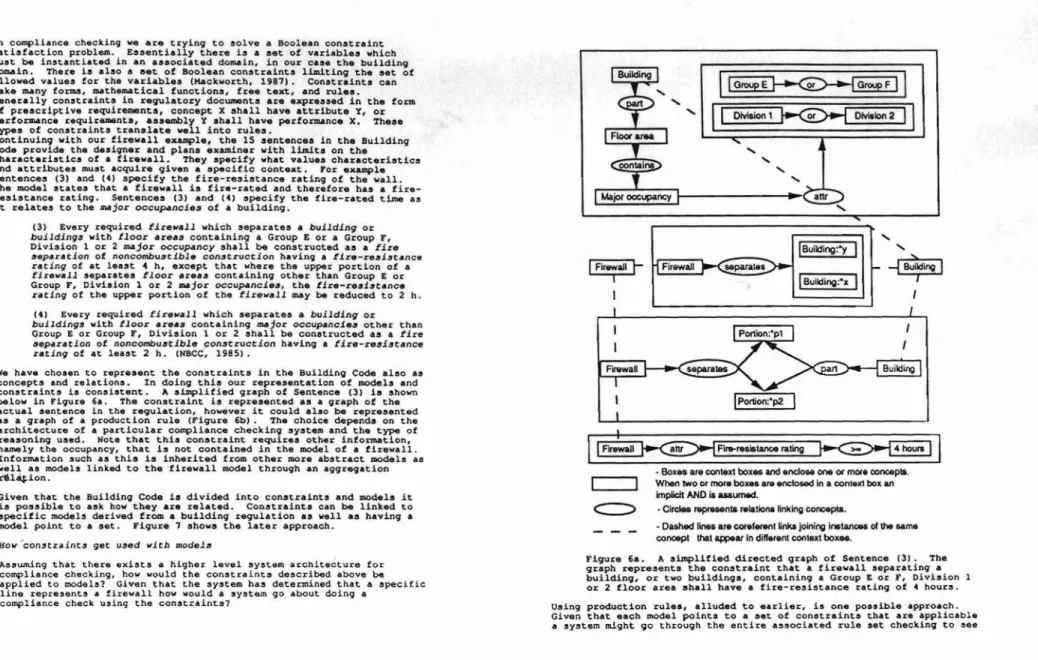
can be represented as networks of dependencies. The graph below shows a
partial dependency network for the attribute parapet_height.
Ordering and dependency netwo<k. are reflected in the layout of the Building Code, the first po<tion of which i. devoted to defining エ・セ
and cla.sifying building••
Checking a de.ign fo< compliance with a regulation can be done in two
way., top-down and bottom-up. A top-down approach to compliance
checking involves deriving important characte<i.tic. of a de.ign in
order to .ati.fy certain high level constraints. For example occupancy
and area would be needed to decide larqer issues such &s adjacency
requirement. or the requirement for .prinkler.. Many .pecific
constraints require knowledge of global characteriatics of a design.
There are times however durinq compliance checkinq when a bottom-up
approach is required. When checking for specific constraints only
certain characteristics need be known. To determine the parapet height
of a firewall only knowledge of the adjacent occupancy types is requi<ed. Dana Vanier IVanier, 1991) ha. looked into the de<ivation of attributes and characteristics and their dependencies in the Buildinq Code.
regulation. Where the<e is a conflict the de.ign fails to meet with
requirements of • requlatlon. The process however is not
a.
cleanlyseparated as the above description implies. Specifically, it is
possible to de<ive a large amount of information from a design but the<e i. little point in de<iving all possible information. This .ituation i. analoqous to the case of & lorward chaining inference engine cycling th<ough a rule-base until no more rule. can be fi<ed. Eventuslly an
answer might be reached, however, information that is unnecessary may
al.o be derived. Ideally, one would like to de<ive only the information
that i. required to check a .pecific regulation. Therefore, the
compliance checking p<oce •• i. driven by the <equi<ement. in the
regulation being u.ed ICoyne, 1990). The process i. depicted in Figure
2.
2hours
knowledge is a cOmbination of 9 1 .
of the designec's experience Zセ・イ。 and Uー・」セヲゥ」 rules that エッセ part
potential .olution must be
・セ。ャオ。エ[セ・キセセセ
of one of the design cycles a regulations (in our case the Building Cod セ・ウー・セエ to appropriatebe • complicated and time consuminq tasK e
E
Tieiev41uation process canchecking process will hel . xarn n ng the compliance
of the design cycle. p us understand aspects of the evaluation phase
A design can be considered 4S 4 systam of 。ウウセャゥ・。
materials. Constituent parts of 4 d 1 ' components, and
characteristics Or attributes C as 90 mdy have predefined
noncombustible material. A 「セゥcォoセセセAエセセウヲッイ example, is セョッキョ to be a
fire-resistance rating. This knowledge is been Nセセキョ to have a 2 hour
part of the background infOrMation of the 「セAセセヲ。 セ ォョセキョ and forms
characteristics of a design must be derived. tィセYウセセ・セエ ・セエィ・イ
derived information about a buildinN i. the b 1ld' 3 ample of
contains a s t f bj i セ u セョァN。イ・。N A design
either
ォョッキョ・ッイッ、・セゥカZセエセcセケセセ
Zセエセゥセセエセ[Yセセセ
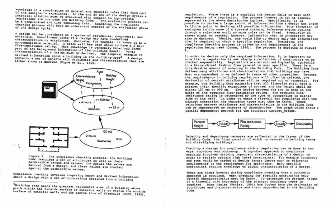
characteristics that areFigure 2. The Compliance checkioq process; the Buildin
COde,describes a set of .ctributes as well as their q
セセssゥ「ャ・ ranqes and values, the actual the values are
er,ved froh Adesign, and these values are checked
sga1nst the permi.sible values.
cセューャゥ。ョ」・ checking involves comparing known and derived information
a ut a design with a set of constraints obtained from a building
3Bu1ldingar h
gr4de
キゥエィゥョ・セィZ・セセZsセ、Z
セセセZZセZエ
ィッイゥコッョセ。ャ
area of a building abovesurface of exterior walls and エィ・oセ・セセエ・イセセイ WAfll'f,or セゥエィゥョ the outside
re 1ne 0 ,rewall. (NBCC, 1985).
4U
- - - -. .
セ
..セセINセ
. . . , J I l .⦅セセ
. .BAG|_N[Niセ
Zセセセセ、sャ・オウウsエoヲ th1e complexity, classifying the elements
o se ect the models to be applied in at a de31gn
process. Whether compliance checking occurs in the compliance checkinqa top-down or bottom-up Ordering in a regulation allows the cotop-down or bottom-up, to proceed in mpliance checking process, whether This structuring however does not
・ョエセイャセゥ」。ャL
constrained fashion. number of constraints to be checked e y solve the problem of the contains 450 pages of rules and re '1 A regulation such as the Code of buildings. A conservative・ウエセエ。エゥセョウ
governing the construction contained in the code would be sev!
°h the number of constraintsdesign
aY。ゥョセエ
several thousand」ッセセセ
i
ousand. To check aウセャN
solution is to restrict the number fra nts is clearly impractical. The eliminating those that are not a ャセ constraints to be checked by about a design then the entire 「セセ cセ「ャセN If there ia no infOrmAtion information about a design 「・coュ・ウyォセ t e regulation applies. As more
tha aet of applicable constraints be own, building .c•• , for eXAmple,
allows us to narrow the range ot a セセュ・ウ SmAller. Classification
is the act of arranging or 、ゥウエイゥ「セセゥ cable constraints. Classification according to a method or system
ko、ョセ
aセッョ」・pエ
or ob'ect into classes regulation and background ゥョヲッセエゥ on cane s, beerived from a buildingused to classify designs.1) The required fire-resistance ratinq for firewall. separatinq
industrial occupancies 1s 4 hours,
2) The required fire-resistance rating for firewalls separating ョッョMゥョ、オウエセゥ。ャ occupancies is 2 hours,
3) The parapet height fOI a 4 hour firewall is 900 mm, 4) The parapet height for a 2 hour firewall i. 150 rom, 5) The aggregate width of the openings within the tirewall is
lLmited to 25' of the length.
Once it is deter.mined th.t • specific line represents a firewall certain
data can be obtained directly trom the design, specifically the length,
height, and construction detaila. Other information, such as the
fire-resistance ratin9, can be derived from the construction detaila. A task
such as code checkinq is thus represented by the process of:
1) classifying the desiqn in order to
、・エ・セョ・
the models thatapply,
2) generating of a set of constraints by joining the constIaints
associated with the appropriate models,
The model associated with the line also points to a set of
」ッョウエセ。ゥョエウL
pertaining to tirewalls. Thus the firewall model, now associated with the line in the drawing, has the following constraints imposed on it:
The reason for selecting an appropriate model is to generate a set of
constraints to be applied to a given design, thus reducing the number of
ゥエセ
to check. Hodels derived from the Buildinq Code have constraintsassociated with them which are to a certain deqxee, encapsulated. Fox
eX&mP
le, Amodel of a firewall carries with it a set of constraints.
The firewall model 1a general in its nature but the constraints serve to
limit its attributes or characteristics under specific conditions.
BRANZ (Hamer, Hosking, , Muqridqe, 1988) have developed 8 system where
objects, such as walls, are
」ッセャ・エ・ャケ
encapsulated.aセ
more knowledgeabout an object become. known it can be reclassified and the applicable constraints updated.
Models allow us to write or derive information about Ade5ign. If we
decide for example that a line on a drawing represents a flrevell
several things are understood. First, a model of a firewall has been
associated with the llne. Associating a model with a line on a drawinq
has the effect of generate a set of expectations or slot. to be tilled.
It
セケ
be possible to assiqn values to these slots from the desiqndirectly, or it may require that values be derived (such as the building
area). The firewall model also tells uS the following things:
1) it separates tWO buildings,
2) it repre.ents a wall assembly,
3) the assembly has a fire-resi.tance rating, 4) the assembly is made of noncombu.tible materials,
5) the wall is made of concrete, or masonry,
6) the wall extends continuously trom the ground to root, 1) the wall extends above the roof to form a parapet of a
specified height,
8) the wall must be structurally stable for the fiIe-rated time. fashion, classification is required to select the appropriate models to apply. Because classifying buildings is done according to the rules and definitions in the Building Code and the models are derived from knowledge in the Building Code, the comparison of designs with models is
in effect classification.
lie
-I-Cr••• S••tionof Fir.",.ll
Floorpャセョ
fャセッイ plan andcrOS8 ,ection of a firewall i
reS1dence of one of the author3. n Villa
Fiqure 3.
- - - -• • • • • •_. . . . .ᄋQセMゥiゥゥゥャゥAijG「AAャAAAB[GB 'b,;,i,'.;;;;.-.:1IA111• • •iエAQヲZウZセ .NLセAB ...Zャエ[N[セA[LNNANNN⦅セMN⦅ ....
3) testing the proposed 、・セゥYョ solution to ensure the solution
satisfies the constraints (i.e. checking the actual values
againat the required valueal .
This corresponds to the process shown in Figure 2.
Building requlationa euch ae the Building Code can be eeparated into two conceptual entitiea. Hodela, which deacribe the objecta that are the aubject of the regulation and conetrainta, which lindt the attributea and characteriatica of the objecta defined in a regulation. Conatrainte also place limite on the relationahipo that can hold between objecta.
hッ、・ャセZ w.hat are they?
Building イ・Yオャ。エゥッョセ are baaed on models in order to maintain the
conaiatency of the requirementa and the loqical framework of the document. Theae modela are rarely made explicit. A large part of our work hae focueoed on explicating the modela contained in the Building Code (Cornick, Leiehman, , Thomae, 1990).
At a high level of abatraction the Building Code can be repreeented aa a
collection of concepts and relations. Examples of 」ッョ」・ーエセ cover
physical objects and more abstract notions such as health, and events.
Relations tie concepts together. For example, above is a relation that
links two objects together. A regulation such as the Building Code
defines a number of concepts unique to it as well as incorporating many concepts external to the document in the form of baCKground information. Models are represented as collections of concepts linked by relations,
and can be represented as a semantic network. Concepts can also be
thought of ao being ordered in a type hierarchy. A type hierarchy consists of concepts linked in order of increasinq specialization. Therefore, the top of the hierarchy containa the moot general concepta.
This relation can be thought of as an ls_a relation. Statinq that a
firewall is_a fire-separation means that:
1) it is a special kind of fire-separation,
2) it inherits all the properties of a fire-separation.
A model of a firewall is shown in Figure 4. The model consists of
」ィ。イ。」エ・イゥウエゥ」セ and attributes of a firewall that make it a
specialization of a fire-separation. It also establishes expectations,
セ」セ。ウ the fact that it セ・ー。イ。エ・ウ spaces.
Knowledge contained in models typically comes from the following sources:
1) Definitiona provided by the building regulation, modela can be developed from definitiona,
2) Supertypes - knowledge is inherited from more general concepts
in the type hierarchy, for example a firewall inherits
information from ita supertype, fire-separation,
3) Subtypes - knowledge is derived from concepts in the type
hierarchy that are more specialized, the attributes and
characteristics of several subtypes may be qeneralized to for.m
a model,
4) External and supplemental sources - this background
information can come from the world or from explanatory
type F1rewIII(x)I.
i 11 x reaeed in teDna of a directed
Figure 4. Partial model of a f rewa ・ィセ circles represent relations
graph. The boxes represent concepts. T as a building or エセッ buildings.
linking the con
7
epta. aヲヲゥイ・セセQQヲセセセセセセQPョ to the roof paeeing throughIt extends 」ッョエセョオッセウャケ rom • above the roof to form a parapet. It
all storeys. The ヲセイ・キ。ャャ ・クエセョセ d also has a fire-resistance rating.
is of noncombustible construct on an b concrete or masonry. Most
The fire reeietance,rating ie ーセセカゥセセャセ for the fire-rated time.
importantly it イ・ュ。セョ structura Y s
- - - _• • • • • • • •li'lO·-..ᄋccゥゥエsゥiᄋ ゥゥゥsゥャゥwャゥゥkァLLG[GセウGB G[[BセGセLウゥゥゥMゥセャiャiB . . . i i ( J ' "-:.1\.\:-:-:-. ,.:...
I
List of Relationsセ
Type Hierarchy•
...
(b) (a) Building Code (c). ceas of building models, a) graph F1qure 5. セセセゥセセセs and definitions, b) generate
セセ・セセZセセイcィy and セ・ャ。エゥoョウ from graphs, c) build
modelS from these sources.
lldln regulations &3 being composed of
As mentioned above, we regard bu f セィ・ models is to define and
mode13 and constraints. The イッャセ °i Models built from concepts in
structure the domain of the regu at on
the
list セヲ relations for.m thethe type hierarchy and イ・ャ。エセッョウ ヲイッセィ・ Building Code will be applied.
context to which the 」ッョウエイaセョゥA、セョ Code constraints generally take
In a requlation such as the Bu セセ s cific at&ributes or
the form of sentences that ーイ・Q」イセ f セョ」・X of components and
characteristics, speiifY セ・イエ。ャセエセセセウセゥーウ between assemblies and
assemblies, or restr ct t セ rehAve the effect of reducinq the eet of
components. Constraints t us
.correctR designs or generative space.
The graph in Figure 4 embodies most of the features of the definition, namely the fact that the wall has a fire-resistance rating, it is made of noncombustible materials, and must be stable. Other information comes from the regulations in the Code, specifically that the wall be constructed of masonry or concrete and that in general firewalls have a parapet.
4 Ha jor occupancy mean, the principal occupancy for which a building or
part thereof is used or intended to be オセ・、L and shall be deemed to
include the subsidiary ッ」」オー。ョ」ゥ・セ which are an integral part of the
principal occupancy (HBCC, 1985).
Firewall means a type ot flre セ・ー。イ。エゥッョ of noncombu8tlble
construction which subdivides a building or separates adjoining
buildings to resist the spread of fire and which has a
fire-イ・セゥウエ。ョ」・ ratlng as prescribed in this Code and has structural
stability to remain intact under fire conditions for the required fire-rated time (NBCC, 1985).
From the type hierarchy more infor.mation can be inherited. The
attributes and characteristics of both fire-separations and wall
aS3emblies are inherited by the firewall model. For example, a
fire-separation may contain openings that must be protected. Consequently,
ヲゥイ・キ。ャャセ may contain openings that must be protected. The firewall
model can be expanded to a considerable degree. For example, the model suggests that a firewall separates two buildings. The model of a
building however states that 「オゥャ、ゥョYセ have a characteristic called
セェッイ occupancy4. The fire-r85iatAnce rating and occupancy
」セaTN」エ・イゥUエゥ」ウ are related. The type of occupancies on either セゥ、・ of
。セゥイ・キ。ャャ 、・エ・セョ・ウ the required fire-resistance rating. Our rnodel3
can inherit ゥョヲッセエゥッョ either directly from the type hierarchy or
indirectly by expanding their component3.
material such as Supplements to the National Building Code or
Commentaries.
The process of developing models involves interpreting each of the
sentence, in a regulation and repreaenting them in ter,ma of concepts and
relations. In order to visualize the sentences, graphs showing how the concepts and relations are linked can be drawn. The graphs are created
for .ach of the sentences in the section 0: interest. From these
graphs, the Building Code (specifically tl." glossary), and background knowledge a type hierarchy of concepts and a list of relations is
qenerated. Hod.la, such as the firewall and fire-separation modela are
then generated by repre,·enting their definitiona (obtained frOID the Code) in tenns of the c. ncepts and relations elicited earlier. The process is depicted in Figure 5.
Consider the development of a model of a firewall from the Building Code. The definition of the flrewall concept in the Building Code
ean
"s" •セI
Building:·yI
Building:·xiセャ
Il
Division 1セ
Division 2• Boxesare conlext boxes and enclose one or more conceplll.
When !Woormore boxes are enclosedinaconleXlbox an
implicitAND is assUll14ld.
- Circlee represenlS relations linkingconcepts.
• Oa&hed lines arecorererenlijnlu;joining instancesofthesarne conOllpt thai appear in different contexl box...
セセMMセ\。ャQエ
Figure 6a. A simplified directed graph of Sentence (31. The
qrAph represents the constraint that a firewall separating a
building, or two buildings, containing a Group E or F, Division
or 2 floor area shall have a fire-resistance rating of 4 hours.
Using production rules, alluded to earlier, is one possible approach.
Given that each model pointe to a set of constraints that are applicable
a system might 90 through the entire associated rule set checking to see
In compliance checklnq we are tryinq to セッャカ・ a Boolean conatraint
satisfaction problem. Essentially there is a set of variables which
must be instantiated in an associated domain, in our case the building
domain. There is also a set of Boolean constraints limiting the set of allowed values for the variables (Hackworth, 1987). Constraints can
take many for.ms, mathematical functiona, free text, and rulea.
Generally constraints in requlatory documents are expressed in the form of prescriptive requirements, concept Xshall have attribute Y, or performance requirements, assembly Yshall have performance X. Theae types of constraints translate well into rules.
Continuing with our firewall example, the 15 sentences in the Building Code provide the designer and plans examiner with limita on the
characteristics of a firewall. They specify what values characteriatics
and attributes must acquire given a specific context. ror example
Sentences (3) and (4) specify the fire-resistance rating of the wall. The model states that a firewall is rated and therefore has a fire-resistance rating. Sentences (3) and (4) specify the fire-rated time as it relates to the major occupancies of a building.
(3) Every required firewall which separates a buildingor
buildings with floor areas containing a Group E or a Group F, Division 1 or 2 major occupancy shall be constructed as a fire
separation of noncombustible 」ッョセエイオ」エゥッョ having a fire-resl$tance
rating of at least 4 h, except that where the upper portion of a
firewall separates floor aceas containinq other than Group Eor
Group F, Division 1 or 2 m.jor ッ」」オセョ」ゥ・セL the lire-resistance
ratingof the upper portion of the firewall may be reduced to 2 h. (4) Every required firewall which separates a building Or
buildings with floor areaS containing セェッイ occupancies other than
Group Eor Group F, Division 1 or 2 shall be constructed as a fire
separation of noncombustible construction having a fire-resistance
rating of at least 2 h. (NBCC, 1985).
We have cho5en to represent the constraints in the Buildin9 Code also as
concepts and relations. In doing this our representation of models and constraints is consistent. Asimplified graph of Sentence (3) ia shown below in Figure 6a. The constraint is represented as a graph of the
ectual sentence in the requlation, however it could a1.0 be イ・ーイ・セNョエ・、
as a graph of a production rule (Figure 6b). 1he choice depends on the architecture of a particular compliance checking system and the type of
reasoning used. Note that thie conatraint requirea other information,
namely the occupancy, that is not contained in the model ot • firewall.
Information such as this is inherited from other more abstract models as well as models linked to the firewall model through an aggregation r1l1.... ion.
Given that the Building Code ia divided into constraints and models it is possible to ask how they are related. Constrainta can be linked to specific models derived from a building regulation as well as having a model point to a set. Figure 7 ahows the later approach.
Hov'con3traints get オセ・、 witb models
Assuncing that there exists a hiqher level system architecture for
compliance checking, how would the constraints described above be
applied to models? Given that the system has determined that a specific
line represents a firewall how would a system go About doing a compliance cheCk using the constraints?
whether a constraint has been violated. If a rule fires then it is
applicable and the design pass.s or fails depondinq on the rule. Rules
that do not tire are not applicable to the current context. This
procedure is セィッキョ in Figure 8.
RuJ.e;
IJ'
Firewalllw) aeparatea Spacelal) and Space(a2) Space(sl) or Space(a2)
has_occupancy«t or F) and (Division 1 Or Diviaion 2»
TIID
Fire-reaistance_rating(Firewall(w» >- 4 hours
Figure 6b. A sLmplified produce ion rule representation of the graph depicted in Figure 6a.
Another approach would be to u3e セッュ・ of the 」セョ」・ーエオ。ャ graph operationa
defined by John Sowa (Sowa, 1984). Although representing a building
regulation as a set of concepts and relations ウ・セ to be a good
approach, the representation is too abstract to do any useful work. To
provide structure and イ・。セッョゥョY power conceptual graphs can be used to
represent the models and constraints. The type hierarchy, relations,
models, constraints, and gr.phs are essentially the same as before.
Sowa's conceptual graphs merely provide us with systematic ways ot
constructing and manipulating these expressions while enforcing selectional constraints.
The conceptual graph model defines specialization operations used for
selectional constraints and generalization operations for logic and
model theory. Of particular interest here are the ァ・ョ・イ。ャゥセ。エゥッョ
ッー・イNエゥッョセN If two conceptual graphs are compared, it is possible to describe a common generalization of the two graphs.
Any two Yイ。ーィセ セゥャャ always have a ャ・。セエ one common generalization, namely [Tl, the universal graph, sinc_ it is a generalization of all
graphs. Consider the two graphs ul and u2 and their common
generalization v. ConstraintSets Model セゥァオイ・ I. Models point to associated セ・エウ of 」ッョセエイ。ゥョエSN Reasoning Mechanism Constrain! Set
Figure 8. AHodel, aConstraint Set,
and a Reasoninq Mechanism, in this 」セウ・
• rule-based plan checker.
Another 9caph operation of interest is the projection operAtor. Given
twO 9 rapha v and u, if v is the more general of the twO, i.e. v is a
generalization of u, chen the projection operation consists of finding a subqraph u· in u subject to the following conditions:
1) the relations linking the concepts in u' and v セイ・ identical,
2) the concepts in u' are identical or speciali.at>ons of the concepts in v,
3) if a relation links two conceptS in v then it also links the
corresponding concepts in u'.
u1:
u2:
カ[セ
The projection of the graph v into ul and u2 is then;
uャGZセ
u2':
ャー・イウッョZウオ・セ
A introduction to conceptual graphs and the basic graph operations can
be found in Leishman (1989). i h f' t
Given &conceptual qraph of a desiqn and ッョセ of,a constra nt, t e lrs A ッセイ。エゥッョ would be to find a common ァ・ョ・イ。ャセコ。エャッョ of the two graphs.
In this paper we have outlined the broader issues relating the design
process, as envls4qed within the construction industry, to computerized
support for such activitiea. The major thrust in this paper has
focused upon the evaluation phase of the design process (Asimow 1962) with the description of a system based upon an existing body of
regulatory codes (NBCC 1985). Within this approach we have identified
the need for both Static and Process models along with their associated constraints imposed by both the regulatory documents and the Users objectives.
The derivation of the static models from the regulatory codes has not only provided us with a clearer understanding of the implicit models contained within the code documents but has also pointed areas of
confusion within the documents エィ・セ・ャカ・ウN By separating the modele
from the constraints imposed by the codes we hope to provide a system which can be adapted to changes in the regulations by chanqing the constraints on the models rather than having to make changes to the
models themselves. Over time, the models contained in regulatory codes
are stable and the chanqee that do occur are qenerally .,sociated with
constraints on the mod.la. The next .tep in our rese.rch prQ9ramme is
the integration of thio system with CAD and an associated object oriented database.
Akin, O. (1988). Expertise of the Architect. In M. D. Rychener lEd.),
Expert System" tor
Engineering Design lpp. 113-196). San Diego, CA: Academic Press, Inc.
Asimow,
w.
(1962). Introductlon to De3ign. Englewood Cliffs, New Jersey:Prentice-Hall. DiecuaaioA
How are mpde]:s and CQo3traint.!l n"efu1")
In a top-down approach the models and their associated conatrainta aerve to generate an envelope within which the remainin91 more apeciali&ed
models must lie. In effect this is the same as classification.
In aummary, modela and constraints are useful in the compliance cheCking
process. Since the models are derived from the Building Code they help
in classifying designs with respect to the Building Code by providing a template Or fr&me to match the design against. They are useful in that once a match i. made a set of expectation. i. generated. This can be a • • imple
a.
a .et of .lots to be filled in or it may repre.ent information to be derived about a design and cheCked against performance criteria. Hodels also provide us with access to layers of inherited information. In a bottom-up approach to compliance checking a model can be expanded, by substituting supertypes, until the required information becomesknown. This is a sort of baCk propagation of constraints (e.g. if the
parapet is 150 mm then the required fire-resistance rating must be two hours therefore the building contains no occupancies of type E or F) .
compliance checking. Another approach might be to represent the logic
of the Building Code separately from the models and constraints. This
knowledge would describe how to propagate the constraints.
Common generalization
Projection 01 corrvnon generaizatJon Intomodel
d)
ifrequired /. value thenfajl セ
L...-_---J
Figure 9. Compliance checking using graph ッー・イ。エゥッョセL a) イ・ーイ・セ・ョエウ a
graph of a model, b) represents a graph of a constraint, c) is the
common generalization of the model and conatraint, d) is the graph of
the projection ッセ the common generalization in the model. Checking the
constraint then セョカッャカ・ウ comparing graphs b) and d) .
I".sue"
Model
セィ・イ・ are 3evecal issues regardinq autOmAted compliAnce checking that have not been fully addressed. The first is that the constraints セエィ・
イセ。エゥッョウI can be related to each other. tィゥセ linking has ゥューャャ」。セゥッョウ in the architecture of any automated cheCking system. There w111 certainly be dependencies Among the attributes and
characteristics derived from the Building Code (probably a direct result
of the fact that the Code is based on implicit models). It is possible
to map エィ・セ・ dependenciea into a ョ・エセッイォ of 」ッョセエイ。ゥョエ。N The creation of 」ッョSエイッセョエ networks from buildinq regulations is similar to work done
by Neal Holtz (1982) on オセゥョY constraint propagation in design and to
the SASE model IFenves, Wright, Stahl, , Reed, 1981).
The second issue is where should this knowledge reside 9iven the
conceptual separation between models and constraints? One approach is
to encapsulate all the appropriate knowledqe in the model and constraint
sets: Thus several models ml9ht point to the same constraint セ。ウ shown
in F1gure 7 above). The constraint dependencies would be contained in the constraint sets. This approach seems to lend itself to rule-based
projection of the 」ッセョ generalization into the graph of the design
would then select a portion ot it セlュゥャNE to the conatraint. The two
graphs can then be compared by matching them. If the match fails then
the constraint is violated. In a design that complies each item ahould
match. If there is no common generalization (i.e. the generalization
returns [TJ) then the constraint does not apply in the current Context
This process is shown in Figure 9. .
- - - I111 • • .O . . . . .. .'1I'... ...:.:.,;!I1llI• • ..•..tr,.
,
to link concepts. Cornick, S. H., Lehhman 0; A., , Tnomas, J. R. (1990). The Integration
of Regulatory Codes with Design Syst.ma. In A. Gulliver (Ed.), Canadian Conference on Electrical and Computer Engineering: Ten Years to 2000, 1 (pp. 14.4.1-14.4.5). Ottawa, Ontario: Canadian Society for Electrical and Computer Engineering. Sept. 4-6.
Coyne, R. (19901. Logic of Design Actions. Knowledge-Based Systems,
3(4),242-257.
Fーー。d、ゥFセN セ type bierercby and rel.tioD. The following are definitions of relations used are taken from Sowa p. 415 (1984).
agADt. (AGENT) links (ACT) to i(ENTITY
Z)' whlere
ゥセZ
セセiセセ
セ[[セZpエ
represents the actor of tne act on. xamp e: .They
where .y is a part
Vehicle5 arrive at
EXAlllPle:
agent
(OBJECT) links an (ACT) to an (ENTITY), which is acted upon.
The cat swallowed the canary.
(PART) links an [ENTITY:·X) to an (ENTITY:"y) Example: A finger ispart ot a band.
セ
aュ「オャNセZG part. of *x. object. Example:material. (MATR) links an [ACT) to a (SUBSTANCE) used in the process. Example: The gun w.... carved out of soap.
maDA8r. (KANNER) links an (ACT) to an (ATTRIBUTE). ambulance arrived quickly.
10cetioD. (LOC) links a (T) to a [PIeACE). Example: • .station.
attribute. (ATTRIBUTE) links [ENTITY:"x) to (ENTITY:"y) wnere 'x has the attribute "y. Example: The rosa is red.
Sowa, J. F. (1984). cッョ」・ーエオNセ Structure3: Information pイッ」・セウャョァ in Hind and Hachine. Don Hills, Ontario: Addison-Wealey.
Vanier, D. J. (1991). A Parsimonious Classification System to Extract P_oject-Specific Building Codea. To appear in Computers andBuilding sエ。イャ、。イ、セN Espoo, Finland.
June 8-15.
Hamer, J., Hosking, J. G., , Hugridge, W. B. (1988). The Evolution of Class L4nguage No. 75 Building Research Association of New Zealand. Holtz, N. H. (1982) Symbolic Hanipulation of Design Constraints. PhD. Theais, Department of Civil Engineering, Carnegie-Hellon University. Leiahman, O. A. (1989) A Principled Analogical Tool. Haatera Theais, Department of Computer Science, University of Calgary.
Hackworth, A. K. (1987). Constraint Satisfaction. In S. C. Shapiro (Ed.), Encyclopedia of Artificial Intelligence (pp. 205-211). New York, New York: Jonn Wiley' Sons.
The National Building Code of Canada. (1985), Ottawa Ontario Canada: National Researcn Council of Canada.
Gero, J. S., , Rosenman, H. A. (1989). A Conceptual Framework for Knowledge-Based Design Research at Sydney University's Design Computing Unit. In J. S. Garo (Ed.), Artificial Intelligence in Design, 1 (pp. 363-382). Cambridge, UK: Computional Hechanics Publications!Springer-Verlag. July.
Coyne, R. 0., Roseman, H. A., Radford, A. D., salachandran, H" セ Gero, J. S. (1990). Knowledge-Based Design Systama. Sydney, Australia: Addiaon-Wesley.
Fenves, S. J., Wrignt , R. N., Stahl, F. I., , Reed, K. A. (1987).
Introduction to SASE: Standards Analysis, Synthesis, andExpression No. NBSIR 87-3513). National Bureau of Standards, U.S. Department of Conmerce.
A partial type hierarchy of concept' derived from the firewall section of tne Building Code.
459 458
• • • • • • • • • • • • • • • • • • • • • •_.iIIT• •Iill.IliT.rlll....Iil• •
UゥQセゥiゥGャゥャᄋゥゥiDZゥiGᆬャQwiᄋャゥᄋャゥGᄋセGQサーエBエGセᄋゥゥャエセGャキNGBG..
Bゥャッセ ..·,..,·... LNNェセMiゥャ[ZゥセゥQmセL^セZ[[U...
t
Fire ...paralion means a conatnJ<;tion a...mblythatac15 aa a
barrier againallhe apread of fire. Shaded boxe. ropr_nt information inhenled from othertypes.
SLbctance-TIme
/""-Matenal Water. /
,
Masonry Concrete Parapet ApertureI
OperOng UnlveruJi セ
セBBBBGB
セNN
._,
-,
..
cッョウャイオ」エ・、セ_
セ
1""'-Flr..reslsWlCe Act Pass Reactlon
rating / \ .
I
Fir..raled Cleate Prevent Chemical
Reaction ConauucUon Through
I
tセ FA / " Fire safety Combustible Noncombustible ConsUUCtion ConstructionMobile entity PhyaObj Spaoe sエ。エゥッョセ entity
..."
\
I
/""-Flame Heat Smoke Artifact Atea Place Ban1er
セO
\セセッイ。j・。
Asser
セ
ゥセ
sエセイ
ConstructIOn assacrbly Closure Buildong
I
Building usacrbly
セ
Fir....paration Wall asoembly
"'-.
, , /
FirewallThis appendix conLains the model of a fire-separation as well as some of
the model. on which it i. ba.ed. 2. Artifact n. An object produced or shaped by human workmanship.
1. A fire-separation means a construction assembly that ,acts as a
barrier against the spread of fire (Shaded boxes represent ゥョヲッセエゥッョ
that has been inherited from other model.) (HBCC. 1985).
- - - -• • • • • • • • • • • • • • • • • • •""rwnlil*o'l-itI'Qiゥャャ|ャZャセエャゥNᄋ _ ⦅NZNセLセL • • •⦅エセZZZコイ_ゥNZZ⦅セセᄋZNZI ...
type Artifact(x) ia
3. Component n. A simple part, ox a relatively complex entity regarded
4S oS part..
type Component(x) is
I
Artlfact'x4. Assembly n. A set of manufactured parts (components).
typeAssembly(x) is
I
Artifact'xセcッューッョ・ョャャャサGyャ
5. Const.ruction assembly. n. An assembly t.hat is constructed, has a deqree of fire ウセヲ・エケL and has a construction type.
type Construclion·usembly(x) is
8. Pass v. To run; extend, to move on or ahead. type Pass(x)i.
セ
' - - -
...
9. Barrier n. Anyt.hinq, mat.erial or immaterial, that acts to obstruct or prevent passage.
typeBarrier(x) Is 6. Building assembly. n. A bullding assembly is a construction
assembly th.t constitut85 part of • building, it may be fire-rated, and it may have a fire-resistance rating.
'"
'/ . Prevent v. To keep from happening, as
Ar.·resistance rating:@