Development of a Guidance, Navigation and Control
Architecture and Validation Process Enabling Autonomous
Docking to a Tumbling Satellite
by
Simon Nolet
B.Ing., Universite de Sherbrooke (1998)
M.Eng., Massachusetts Institute of Technology (2001) Submitted to the Department of Aeronautics and Astronautics
in partial fulfillment of the requirements for the degree of Doctor of Science
at the
MASSACHUSETTS INSTITUTE OF TECHNOLOGY June 2007
©
Massachusetts Institute of Technology 2007. All rights reserved.Author... ... ...
Department of Aero autics and Astronautics ay 25 2007 Certified by... ...
.
'
. . . ..David W. Miller Professor of Aeronautics and Astronautics Thesis Supervisor Certified by.. Associate Professor of Certified by Professor of Jonathan P. How Aerqiaut cs ald As orvutics ... .
J~hnJ. Deyst Jr. Aeronauqij,,.an onautics Certified by.. ... \- . . . .
-und . g
Senior Principal En gieer Orb lS es Corpor tion Accepted by...
MAssACHUSETTS INSTITUTE
JU TE1HLOGY
JUL--200
'Jaime Peraire Professor of Aeronautics and Astronautics Chair, Committee on Graduate Students
Development of a Guidance, Navigation and Control
Architecture and Validation Process Enabling Autonomous
Docking to a Tumbling Satellite
by
Simon Nolet
Submitted to the Department of Aeronautics and Astronautics on May 25, 2007, in partial fulfillment of the
requirements for the degree of Doctor of Science
Abstract
The capability to routinely perform autonomous docking is a key enabling technology for future space exploration, as well as assembly and servicing missions for spacecraft and commercial satellites. Particularly, in more challenging situations where the tar-get spacecraft or satellite is tumbling, algorithms and strategies must be implemented to ensure the safety of both docking entities in the event of anomalies. However, dif-ficulties encountered in past docking missions conducted with expensive satellites on orbit have indicated a lack of maturity in the technologies required for such opera-tions. Therefore, more experimentation must be performed to improve the current autonomous docking capabilities.
The main objectives of the research presented in this thesis are to develop a guidance, navigation and control (GN&C) architecture that enables the safe and fuel-efficient docking with a free tumbling target in the presence of obstacles and anomalies, and to develop the software tools and verification processes necessary in order to successfully demonstrate the GN&C architecture in a relevant environment. The GN&C architecture was developed by integrating a spectrum of GN&C algo-rithms including estimation, control, path planning, and failure detection, isolation and recovery algorithms. The algorithms were implemented in GN&C software mod-ules for real-time experimentation using the Synchronized Position Hold Engage and Reorient Experimental Satellite (SPHERES) facility that was created by the MIT
Space Systems Laboratory. Operated inside the International Space Station (ISS), SPHERES allow the incremental maturation of formation flight and autonomous docking algorithms in a risk-tolerant, microgravity environment.
Multiple autonomous docking operations have been performed in the ISS to validate the GN&C architecture. These experiments led to the first autonomous docking with a tumbling target ever achieved in microgravity. Furthermore, the author also demonstrated successful docking in spite of the presence of measurement errors that were detected and rejected by an online fault detection algorithm.
The results of these experiments will be discussed in this thesis. Finally, based on experiments in a laboratory environment, the author establishes two processes for the verification of GN&C software prior to on-orbit testing on the SPHERES testbed.
Thesis Supervisor: David W. Miller
Acknowledgments
This piece of work would not have been possible without the help of a lot of people around me. Over the 5 1/2 years spanned by this research, I had the chance to work with incredible people. This is where I want to thank them for all their help. I
apologize in advance to whoever I might have forgotten in this list.
I first want to thank my committee, Prof. David Miller, Prof. Jonathan How, Prof. John Deyst, and Dr. Edmund Kong. They were the ones who kept me on track throughout this research. They supported me all the way through, and provided me with great ideas when it was needed the most. Prof. David Miller should be especially acknowledged for having given me the opportunity to work on the SPHERES project. I owe him tremendously. He was also very patient and helpful at every step of my doctorate, including when writing this thesis. Moreover, he is the one who kept the SPHERES team alive and led it to the ISS, despite continuous delays in the program, following the Columbia accident. Dr. Edmund Kong should be also particularly acknowledged for giving me day-to-day support for the first four years of my research. He was a constant source of ideas for research avenues and a great team leader.
Thanks also to my readers, Prof. Olivier de Weck and Dr. Ray Sedwick, for their help not only when writing my thesis, but also at different stages of my doctorate program, whether it was help in preparing for the Qualification or the General Exams. A lot of my learning comes from the tremendous people I worked with on a day-to-day basis. I want to thank here the whole SPHERES team, who changed a lot over the years I was part of it (Alvar Saenz-Otero, Mark Hilstad, Allen Chen, John Enright, Dustin Berkovitz, Swati Mohan, Nick Hoff, Chris Mandy, Amer Fejzic, Soon-Jo Chung, Danielle Adams, and all the UROPs and other students who worked part-time with us). SPHERES is a team effort and everybody fulfilled their role, which facilitated my life a lot. In particular, I want to thank Dr. Alvar Saenz-Otero, who deserves enormous credit not only for his help with everything regarding the SPHERES facility, but also for his support in this research. The work presented in this thesis relied on the SPHERES facility, and Alvar is in my mind the one who
contributed the most to its design. I also want to acknowledge the students I worked with from the ACL, especially Arthur Richards (whose aura of intelligence still hovers around MIT), Louis Breger and Georges Aoude. Other guest scientists gave me great ideas throughout this research, including Dr. Edward Wilson from Intellization.
Another group of people that deserves particular credit is the whole team at Payload Systems, Inc. In particular, I want to thank Steve Sell, Stephanie Chen, Javier de Luis, Joe Parrish, Edison Guerra, John Merk and Joanne Vining. They are the ones who put SPHERES together. My research heavily relied on two things: a reliable testbed, and a testbed on ISS. They provided me with that.
I also want to thank the people from the different NASA and DoD centers for their support when performing experiments. In particular, thanks to Linda Brewster, Richard Howard and their team from NASA MSFC, John Yaniec and his team from the JSC Reduced Gravity Program, and, finally, Mark Adams, Major Matthew Budde and their team from the DoD STP office.
The staff in the MIT SSL has also been very supportive to me over the years. Thanks to Paul Bauer, who always had answer to ANY question I asked him, and who was enormously helpful when working with hardware. Thanks also to Marilyn Good, Sharon Leah Brown and Kathryn Fischer (from the ACL) for their help and kindness with office related activities.
Merci aussi au Fonds quebecois de la recherche sur la nature et les technologies (anciennement FCAR) pour leur soutien financier tout au long de mes 6tudes graduees au MIT.
I now want to thank the dearest persons in my life, my whole family, whom I owe the most for their love and infinite support, including countless sacrifices they made for me. Without them, I would not have made it. Plus particulierement, merci a mon frere Etienne et a sa conjointe Catherine pour tous les encouragements. Merci, maman et papa, pour vous avoir tant sacrifies pour moi, et pour toutes les fois oii vous 8tes venus pour vous occuper de Claire. Merci aussi 'a tous ceux qui sont passes avant moi, incluant mes grands-parents (sp6cialement a mon grand-pere Cogne qui m'a donn6 le gofit pour les sciences lorsque j'6tais enfant), et mon parrain Raymond.
Merci aussi a Claire, dont la naissance a te le moment le plus heureux de mon doctorat. Claire,
j'ai
vraiment hite de pouvoir te lire ces quelques lignes dans les annees qui vont venir. La,j'espere
juste pouvoir me rattraper pour le temps que je n'ai malheureusement pas pu passer avec toi comme tu l'aurais tant merite. Tu es vraiment 'enfant ideale qu'un parent puisse esp6rer. But above all, the person who was the most supportive is my wife Xue'en. Merci, Xue'en, tu es sans doute la raison m~me pour laquelle je suis encore la aujourd'hui. Sans toi, je n'y serais pas arrive. Je t'aime!Finally, I want to dedicate this thesis to a special person for me, a person who has been fighting for her life for almost two years now. This person is my mother-in-law. When I torn ligaments in my knee while playing softball with the lab's team, she came over all the way from San Francisco and help me out for a whole month. When Claire was born, she came again, this time for four months, to give us a hand, such that I can pass my General Exam that summer. A year later, only two weeks after Xue'en defended her thesis, we learned that she had brain cancer, terminal phase. Her fight was a constant inspiration for me, and I am so happy that, against all odds, she is still there such that one week from now, I will be able to tell her in person that I made it.
Mommy, this one is for you...
Contents
1 Introduction 33
1.1 M otivation . . . . 34
1.2 Previous autonomous docking and inspection missions . . . . 37
1.3 Previously proposed strategies for docking to a tumbling target . . . 44
1.4 A previously proposed GN&C architecture . . . . 47
1.5 Problem statement . . . . 47
1.6 Thesis approach . . . . 50
1.6.1 Software modularity . . . . 51
1.6.2 Hardware-in-the-loop demonstrations . . . . 52
1.6.3 Verification & validation methodologies . . . . 52
1.7 Thesis roadm ap . . . . 55
1.8 M ain contributions . . . . 56
2 Review of GN&C algorithms for autonomous docking 59 2.1 Review of estimation algorithms . . . . 60
2.1.1 Continuous-discrete extended Kalman filter (EKF) . . . . 61
2.1.2 Discrete-time unscented Kalman filter (UKF) . . . . 64
2.1.3 Particle filter (PF) . . . . 67
2.1.4 Summary of estimation algorithms . . . . 70
2.2 Review of control algorithms . . . . 70
2.2.1 PID-type control algorithm with a pulse-width modulator . . 71
2.2.2 Phase plane control algorithm . . . . 74
2.2.4 Summary of control algorithms . . . . 2.3 Review of path planning algorithms . . . .
2.3.1 Optimal path planning using MILP 2.3.2 Robust path planning through MPC 2.3.3 The glideslope algorithm . . . . 2.3.4 Summary of path planning algorithms 2.4 Review of FDIR algorithms . . . .
2.4.1 FD through filter innovation analysis . 2.4.2 Motion-based thruster FDI . . . . 2.4.3 Bank of Kalman filters . . . . 2.4.4 FDI through parity vector analysis . . 2.4.5 FDI through particle filters . . . . 2.5 Summary of FDIR algorithms . . . . 2.6 Summ ary . . . .
3 Implementation of GN&C algorithms
3.1 The SPHERES testbed . . . . 3.1.1 Background information . . . . 3.1.2 Relevant hardware subsystems . . . . . 3.1.3 Ground operations . . . . 3.1.4 Flight operations . . . . 3.2 The Guest Scientist Program . . . . 3.2.1 Software interface on SPHERES . . . . 3.2.2 The C simulation . . . . 3.2.3 The MATLAB® simulation . . . . 3.3 A GN&C architecture for autonomous docking 3.3.1 GN&C architecture overview . . . . 3.3.2 Software module categorization . . . . 3.4 Implementation of estimation algorithms . . .
3.4.1 The global state estimator . .
. . . 77 . . . . 78 . . . . 79 . . . . 81 . . . . 82 . . . . 84 . . . . 85 . . . . 86 . . . . 86 . . . . 88 . . . . 89 . . . . 89 . . . . 91 . . . . 92 93 . . . . 94 . . . . 95 . . . . 100 . . . . 108 . . . . 108 . . . . 112 . . . . 114 . . . . 115 . . . . 116 . . . . 118 . . . . 119 . . . . 120 . . . . 122 . . . . 123
3.4.2 The relative state estimator . . . . 3.5 Implementation of control algorithms . . . . 3.5.1 PID-type controllers . . . . 3.5.2 Thruster pulse-width modulator . . . . 3.5.3 Phase plane controllers . . . . 3.6 Implementation of path planning algorithms . . . 3.6.1 The glideslope controller . . . . 3.6.2 Advanced path planning algorithms . . . . 3.7 Implementation of FDIR algorithms . . . . 3.7.1 FD through filter innovation analysis . . . 3.7.2 Motion-based thruster FDI . . . . 3.8 Implementation of mission & vehicle management 3.9 Sum m ary . . . .
algorithms
4 Experimental validation of the GN&C modules
4.1 Laboratory experiments . . . . 4.1.1 Major difficulties in early testing . . . . 4.1.2 State estimator performance . . . . 4.2 KC-135 experiments . . . . 4.2.1 Attitude controller testing . . . . 4.2.2 Glideslope controller testing . . . . 4.3 ISS experiments . . . .
4.3.1 Attitude slew experiment . . . .
4.3.2 Beacon tracking experiment . . . . 4.3.3 Position-hold, single beacon estimator experiment . . . . 4.3.4 Docking to a fixed beacon experiment . . . . 4.3.5 Global estimator experiments . . . . 4.4 Sum m ary . . . . 5 Software integration 5.1 Software considerations . . . . 133 143 143 146 146 148 148 149 150 150 151 152 153 155 156 157 165 168 170 171 173 174 176 177 180 184 188 191 193
5.1.1 Module inputs and outputs . . . . 5.1.2 Known module limitations . . . . 5.2 Hardware considerations . . . . 5.2.1 Computational load . . . . 5.2.2 Sharing information between modules . . . . 5.2.3 Telemetry handling . . . . 5.2.4 Tracking curved trajectories . . . . 5.3 Ground experiments . . . . 5.3.1 Docking with a fully cooperative target . . . . 5.3.2 Docking with the target controlling only its attitude . 5.3.3 Docking to a tumbling target (rotating in a 2-D plane) 5.3.4 GN&C mode sequencing summary . . . . 5.4 Flight experiments . . . . 5.4.1 Position-hold, leader and follower . . . . 5.4.2 Position-tracking, leader and follower . . . . 5.5 Implementation of the GN&C architecture . . . . 5.6 Sum m ary . . . . 193 197 199 199 202 202 202 203 204 209 212 215 216 217 217 219 222
6 Autonomous docking experimentation onboard the ISS 225
6.1 Docking to a cooperative target . . . . 226
6.2 Docking to a drifting target . . . . 228
6.3 Docking to a cooperative target with FD enabled . . . 230
6.4 Safe docking with a cooperative target . . . . 232
6.5 Autonomous docking to a tumbling target . . . . 234
6.6 Sum m ary . . . . 238
7 Synthesis of a verification & validation process 7.1 SPHERES as a validation platform . . . . 7.2 Initial V&V process . . . . 7.3 V&V process using simulation tools . . . . 7.4 Sum m ary . . . . 241 242 245 250 254
8 Conclusions and recommendations
8.1 Thesis summary . . . . 8.2 Contributions . . . . 8.3 Recommendations for future work . . . . 8.4 Concluding remarks . . . .
A Technology Readiness Levels
A. 1 Introduction . . . . A.2 Definitions . . . . A.3 TRL detailed description . . . .
B Navigation sensor specifications and models B.1 Gyroscope specifications . . . . B.2 Accelerometers specifications . . . . B.3 Ultrasound metrology calibration . . . .
C Propulsion subsystem theoretical performance C.1 Theoretical thrust . . . . C.2 Specific impulse . . . . C.3 Tank lifetime . . . . C.4 AV capability . . . . C.5 Tank leak rate . . . .
D SPHERES fact sheets
E ISS experiments overview
. . . . . . . . . . . . . . . . . . . . . . . . . . . . . . . . . . . . . . . . . . . . . . . . . . . . . . . . . . . . 255 255 257 260 263 265 265 266 267 269 269 274 278 283 283 285 286 286 287 289 299
List of Figures
1-1 The first automatic docking by Cosmos-186 -188. . . . . 38
1-2 The Progress resupply vehicle. . . . . 39
1-3 The Japanese ETS-VII experiment. . . . . 40
1-4 The XSS-10 micro-satellite. . . . . 41
1-5 The XSS-11 micro-satellite. . . . . 41
1-6 The DART rendezvous vehicle. . . . . 42
1-7 The Orbital Express flight demonstration. . . . . 43
1-8 A proposed strategy for docking to a spinning target. . . . . 46
1-9 A typical control architecture used for automated docking [40]. ... 48
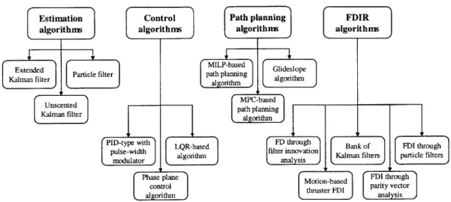
2-1 Overview of the algorithms presented in Chapter 2. . . . . 60
2-2 Input and output for a typical state estimation algorithm. . . . . 61
2-3 Input and output for a typical control algorithm. . . . . 71
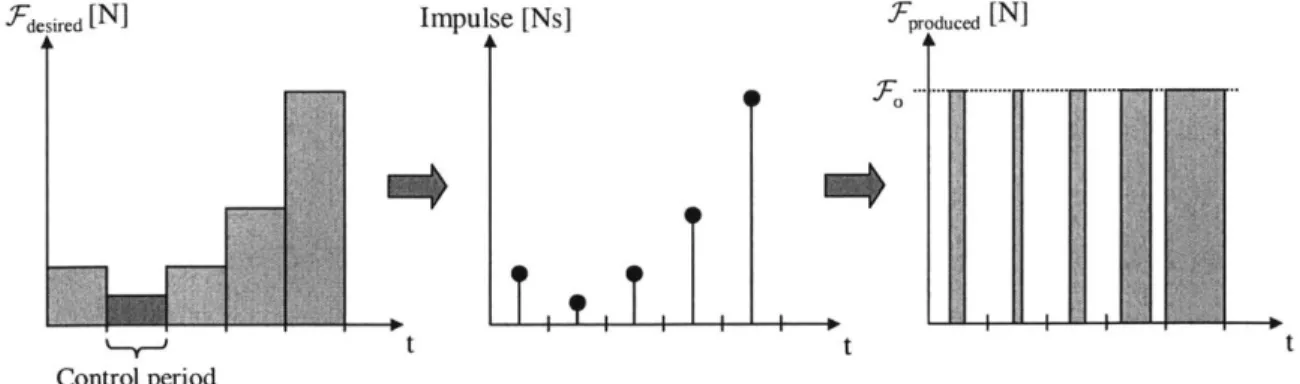
2-4 Conversion of the thrust commanded to thruster ON/OFF time. . . . 73
2-5 Phase plane logic for attitude control (upper half only). . . . . 75
2-6 Input and output for a typical path planning algorithm . . . . 79
2-7 Typical control loop using the MPC algorithm [104]. . . . . 82
2-8 Approach velocity profile computed by the glideslope algorithm. . . . 83
3-1 Overview of Chapter 3. . . . . 94
3-2 SPHERES hardware. . . . . 96
3-3 M IT SSL 2-D air table. . . . . 96
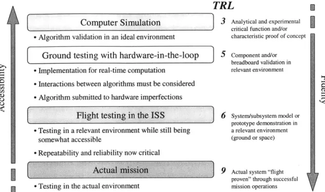
3-4 ISS experimentation to increase the TRL of docking algorithms. . . . 98
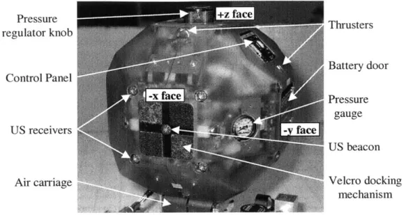
3-5 Visible components around the satellite and body axes. . . . . 99 15
3-6 3-7 3-8 3-9 3-10 3-11 3-12 3-13 3-14 3-15 3-16 3-17 3-18 3-19 3-20 3-21 3-22 4-1 4-2 4-3 4-4 4-5 4-6 4-7 4-8 4-9 4-10 4-11 4-12
Data collected by the ultrasonic sensor system
[57].
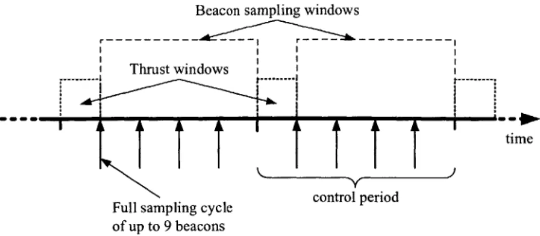
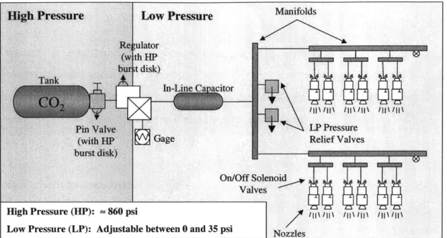
. . . . . TOF recording periods for each of the nine beacons. . . . . . TOF recording periods with a reduced number of beacons. . Typical thrust and estimation pattern. . . . . The SPHERES propulsion subsystem .. . . . . Launch of Progress 21P. ...Typical SPHERES setup in the U.S. Laboratory on ISS. . . GSP information flow diagram [38]. . . . . Different levels of computational processes. . . . . Information flow in the MATLAB® simulation. . . . . A hierarchical view of the GN&C architecture on SPHERES.
Measurement updates during a full sampling cycle of the 5 beacons. Beacon location (r) in the satellite body frame (x, y, z). . . . . Attitude angular error around the Euler axis (n). . . . . Relative state estimates, 2-D problem. . . . . Implementation of the glideslope algorithm along the docking axis. . Process used for gyro-based thruster FDI. . . . .
Overview of Chapter 4. . . . . Jumps in the state estimates output by the EKF. . . . . Measurement rejection system based on filter innovation... Technique to corrupt the raw U/S TOF data. . . . . Total innovation recorded during ISS operations. . . . . Temporary divergence of the state estimates output by the EKF Jumps in the absolute x-position estimate. . . . . Position estimates of a satellite in the middle of the test area. Convergence of the velocity estimates. . . . . Beacon location estimate in the satellite's body frame. . . . . . SPHERES experiments inside NASA's KC-135. . . . . Beacon tracking experiment results: KC-135, November, 2003. .
124 137 138 141 149 152 . . . 156 . . . 157 . . . 161 . . . 161 . . . 162 . . . 163 164 166 167 168 . . . 170 . . . 171 . . . . . 101 . . . . . 104 . . . . . 104 . . . . . 106 . . . . . 107 . .. . . 110 . . . . . 112 .. .. ... 113 . ... 115 . . . . . 116 . . . . . 120
4-13 Glideslope docking experiment results: KC-135, November, 2003. . . . 172
4-14 SPHERES experiments inside the ISS. . . . 174
4-15 Results for the attitude slew experiment. . . . 175
4-16 Results for the beacon tracking experiment. . . . 177
4-17 Results for the position-hold experiment with a fixed beacon. . . . 178
4-18 Closer view on the results for the position-hold experiment. . . . 179
4-19 Results for the docking experiment with a fixed beacon. . . . . 182
4-20 Autonomous docking maneuver to a fixed beacon. . . . . 183
4-21 Global navigation states for two satellites separated by -0.2 meter. . 186 4-22 State telemetry using the global estimator in the ISS. . . . . 187
5-1 Overview of Chapter 5. . . . . 192
5-2 Percentage of the total computation time taken by each process. . . . 201
5-3 Feasible angular rates for circular trajectories at constant velocity. . . 203
5-4 SPHERES docking experiments on the MIT SSL 2-D air table. . . . . 204
5-5 Mode sequencing, docking to a cooperative target. . . . 206
5-6 Autonomous docking with a fully cooperative target. . . . 208
5-7 Velocity tracking, docking to a cooperative target. . . . 208
5-8 Mode sequencing, docking to a target controlling its attitude . . . . . 210
5-9 Autonomous docking with the target controlling its attitude. . . . 211
5-10 Velocity tracking, docking with the target controlling its attitude. . . 211
5-11 SPHERES experiments at NASA MSFC. . . . 212
5-12 Mode sequencing, docking to a tumbling target. . . . 213
5-13 Autonomous docking with a tumbling target (2-D). . . . 214
5-14 Velocity tracking, docking with a tumbling target (2-D). . . . . 215
5-15 Mode sequencing for the formation flight experiments . . . 217
5-16 Position hold experiment, leader and follower. . . . 218
5-17 3-D formation flight experiment. . . . 220
5-18 A detailed view of the GN&C architecture on SPHERES. . . . 221
6-1 Autonomous docking with a cooperative target in microgravity. . . . 227
6-2 Docking with a cooperative target, chaser initially tumbling. . . . . . 228
6-3 Autonomous docking with a drifting target in microgravity. . . . . 229
6-4 Docking with a cooperative target with U/S measurement FD. . . . . 231
6-5 Navigation error detection system, docking to a cooperative target. 231 6-6 Autonomous docking following a safe trajectory, with faults. . . . . . 233
6-7 Autonomous docking following a safe trajectory, no faults. . . . . 234
6-8 Autonomous docking with a tumbling target, first run. . . . . 236
6-9 Docking to a tumbling target: trajectory for the first run. . . . . 236
6-10 Navigation errors, docking to a tumbling target, first run. . . . . 237
6-11 Autonomous docking with a tumbling target, second run. . . . . 238
6-12 Docking to a tumbling target: trajectory for the second run. . . . . . 239
6-13 Navigation errors, docking to a tumbling target, second run. . . . . . 239
7-1 Process used to verify the software before uploading it to the ISS. . . 246
7-2 Increase in the success rate of the experiments . . . . 249
7-3 Process to verify the software using simulation tools. . . . . 251
B-1 General information on the SPHERES gyroscopes [3]. . . . . 271
B-2 SPHERES gyroscopes specifications [3]. . . . . 272
B-3 SPHERES gyroscopes frequency response. . . . . 273
B-4 SPHERES gyroscopes resonance at 338 Hz. . . . . 273
B-5 General information on the SPHERES accelerometers [2]. . . . . 275
B-6 SPHERES accelerometers specifications [2]. . . . . 276
B-7 SPHERES accelerometers frequency response (magnitude). . . . . 277
B-8 SPHERES accelerometers frequency response (phase). . . . . 277
B-9 Response of the U/S receiver to a low intensity sonic wave. . . . . 278
B-10 Response of the U/S receiver to a high intensity sonic wave. . . . . . 278
B-11 Gain lobes for the U/S receivers and transmitters. . . . . 279
B-12 Varying parameters in the U/S system calibration . . . . 280
C-1 The SPHERES CO2 tank assembly (tank and pin valve). . . . 287
List of Tables
1.1 Historical review of autonomous docking missions Brief comparison of estimation algorithms.
Brief comparison of control algorithms... Brief comparison of path planning algorithms. Brief comparison of FDIR algorithms... Timing corresponding to each beacon address SPHERES ground operations time table . . . SPHERES ISS operations time table...
4.1 Final attitude error after completing the three rotations. 5.1
5.2 5.3 5.4
5.5
Inputs and outputs for the estimation modules. Inputs and outputs for the control modules... Inputs and outputs for the path planning modules. Inputs and outputs for the FDIR modules. . . . . . GN&C modes, docking to a cooperative target. . .
5.6 GN&C modes, docking with the target controlling its attitude. 5.7 GN&C modes, docking to a tumbling target. . . . . 5.8 GN&C modes, formation flight experiments on ISS. . . . .
7.1 Anomalies occurring in past missions . . . . A.1 TRL description by the Army for software [50]. . . . . A.2 TRL description by NASA [78]. . . . .
44 2.1 2.2 2.3 2.4 3.1 3.2 3.3 . . . . 70 . . . . 78 . . . . 84 . . . . 9 2 . . . . 103 . . . . 109 . . . 111 175 195 196 197 198 206 210 213 216 244 267 . . . . 268
B.1 Gyroscope anti-aliasing FIR filter coefficients . . . . B.2 Center of acceleration for each accelerometer in the body frame. B.3 Measurement errors at different transmitter ang
B.4 Measurement errors at different receiver angles. Theoretical thrust determination. . . . . Specific impulse for typical regulator settings. Tank lifetime for typical regulator settings. AV capability for typical regulator settings.
les. . . . . 281 . . . . 281 . . . . 285 . . . . 286 . . . . 286 . . . . 287 C.1 C.2 C.3 C.4 D.1 D.2 D.3 D.4 D.5 D.6 D.7 D.8 D.9 E.1 E.2 E.3 E.4 E.5
E.6 ISS test session 06 overview. . . . . 305
270 274
Satellite S/N 1 fact sheet. . . . . 290 Satellite S/N 2 fact sheet. . . . . 291 Satellite S/N 3 fact sheet. . . . . 292 Satellite S/N 4 fact sheet. . . . . 293 Satellite S/N 5 fact sheet. . . . . 294 Satellite S/N 6 fact sheet. . . . . 295 Master fact sheet, 1 of 3. . . . . 296 Master fact sheet, 2 of 3. . . . . 297 Master fact sheet, 3 of 3. . . . . 298 ISS test session 01 overview. . . . . 300 ISS test session 02 overview. . . . . 301 ISS test session 03 overview. . . . . 302 ISS test session 04 overview. . . . . 303 ISS test session 05 overview. . . . . 304
List of Acronyms
2-D Two dimensions
3-D Three dimensions
A/D Analog to digital signal converter ACL Aerospace Controls Laboratory AVGS Advanced Video Guidance Sensor CAM Collision avoidance maneuver
CEV Crew Exploration Vehicle
CG Center of gravity
DARPA Defense Advanced Research Projects Agency
DART Demonstration of Autonomous Rendezvous Technology
DoD Department of Defense
DOF Degree-of-freedom
EKF Extended Kalman filter
ESA European Space Agency
ETS-VII Engineering Test Satellite VII
FD Failure detection
FDI Failure detection and isolation
FDIR Failure detection, isolation and recovery FPGA Field Programmable Gate Array
GN&C Guidance, navigation and control GPS Global Positioning System
GSP Guest Scientist Program
INS IR ISS LP LQR KF MILP MIT MoIRs MOSR MPC MSFC MVM NASA NASDA NRL OS PD PDF PF PID RF RSO RV RVSF S/N SPHERES SSL SWARM TOF
Inertial navigation sensors Infrared
International Space Station Linear program
Linear-quadratic regulator Kalman filter
Mixed-integer linear programming Massachusetts Institute of Technology Moment of inertia ratios
Mars Orbiting Sample Retrieval experiment Model predictive control
Marshall Space Flight Center Mission and vehicle management
National Aeronautics and Space Administration National Space Development Agency
National Research Laboratory Operating system
Proportional-derivative Probability density function Particle filter
Proportional-integral-derivative Radio frequency
Resident space object Rendezvous
Rendezvous flight software Serial number
Synchronized Position Hold Engage and Reorient Experimental Satellites Space Systems Laboratory
Synchronized Wireless Autonomous Reconfigurable Modules Time-of-flight
TRL Technology Readiness Levels UKF Unscented Kalman filter
U/S Ultrasonic
U.S. United States
V&V Verification and validation XSS Experimental Satellite System
pL-g Microgravity
Nomenclature
a [scalar] Slope in the phase plane of the desired velocity profile used by the glideslope algorithm
A [scalar] Area in meters2 A [1 x 1] Jacobian matrix of f(
b [3x1] Vector of gyroscope biases in radians/second
B [scalar] Blowdown multiplier affecting all the thrusters caused by a sudden pressure drop
B [1 x N] Control effect matrix
c [scalar] Speed of sound in meters/second
c [p x 1] Vector of bounds
C [scalar] SPHERES tank capacity in kilograms
C [6x1] Vector of commanded forces and torques d [3x1] Vector of displacements in meters
D [scalar] Duty cycle in %
D [3 x N] Matrix of unit vectors indicating the thrust direction in the body frame
E[] Matrix of expectation functions
f( [1 x 1] Vector of nonlinear functions expressing the dynamics of the system
F [3x1] Vector of commanded forces in the body frame in newtons F [Nx1] Vector of thruster strength for each ON/OFF thruster in
g [scalar] Earth's gravitational constant (9.81 meters/second2)
G [P x 1] Matrix of constraint functions on the states
h [nk x1] Vector of expected measurements given the states in meters
H Ink x 1] Jacobian matrix of h
I [scalar] Inertia in kilograms.meters2
I [3x 3] Inertia tensor (matrix) in kilograms.meters2 ISP [scalar] Specific impulse in seconds
T7 Identity matrix
J [scalar] Cost to be optimized
Kd [scalar] Derivative gain
Ki [scalar] Integral gain
Kp [scalar] Proportional gain
K [1 x nk] Kalman gain matrix 1 [scalar] Length of the state vector
L [3xN] Matrix containing the x-y-z location in the body frame of each thruster in meters
m [scalar] Mass of the satellite in kilograms
M [scalar] Very large number as compared with the elements of the state vector
M [Nx6] Thrust mapping matrix
n [scalar] Number of measurements collected
n [3x1] Unit vector defining the direction of the Euler axis for a rigid body rotation
N [scalar] Number of thrusters
N[] Vector of normally distributed functions p [scalar] Number of constraint functions
p() Vector of probability density functions
P P q
Q
Q
r R R 'R.( sgn() S S t T T T 'U U V AV Wimean [1 x 1] [scalar] [4x1] [l x 1] [l x 1] [3x1] [scalar] [nk x nk [N x N] [scalar] [scalar] [I x (1 -[scalar] [scalar][scalar]
[3x1] [scalar] [Nxl] [3x1][scalar]
[scalar] WCOV [scalar] Covariance matrixControl period in seconds
Attitude component of the state vector (quaternions) Process noise covariance matrix
State weighting matrix
Position component of the state vector in meters Ideal gas constant joules/ (kilogram-kelvin) Measurement noise covariance matrix Control input weighting matrix
Signum function (returns 1, 0 or -1 depending on the sign of the input)
Number of steps in the problem
1)] Matrix used to transition from the reduced form to the ex-panded form
Time in seconds
Temperature in kelvins
Total period used by the glideslope algorithm in seconds Vector of commanded torques in the body frame in new-tons.meters
Velocity in meters/second Control input vector
Velocity component of the state vector in meters/second A change in velocity in meters/second
Weighting parameter associated with the sigma-point vector i (UKF)
Weighting parameter associated with the sigma-point vector i (UKF)
W x X y Y [IHx1] [lx1]
[l x H]
[p x l] [scalar] [scalar] [nk xl] [scalar] [scalar] [(21+1) [scalar]Vector or particle weight (PF) State vector
Matrix where each column represents a sample (particle) of a PDF (PF)
Vector of binary variables
Discrete state variables for the hybrid PF representing the current mode
Calibrated measurement in meters
Vector of calibrated measurements in meters
Matrix containing the measurement history up to time t Adiabatic index
Design parameter for the UKF
x1] Vector of parameters necessary to reconstruct the covariance matrix (UKF)
The magnitude of the position component of the state vector in meters
The magnitude of the projection of the position vector along the y-body axis of the target in meters
The magnitude of the projection of the position vector along the z-body axis of the target in meters
Some tolerance close to zero
Vector of independent zero-mean white noise processes with covariance
Q
Damping ratio of the complex poles for a second order sys-tem
Attitude angular error around the Euler axis in radians Pitch bearing angle in radians
Yaw bearing angle in radians
z z Z -y F 6Y [scalar] 6z C Oe Opitch Oyaw [scalar] [scalar]
[l
x 1] [scalar] [scalar] [scalar] [scalar]0 t A A V p [3x3] [scalar] [3x3] [3x1] [nk xl]1 [4 x 3] [scalar] pframe [3x 1] Qframe [3x1] 1I T -Ir V x [scalar] [lx 2l] [scalar] [scalar] [nk x1] [nk xl]1 [I x 1] [scalar] [l x (21+1)]
Attitude matrix changing a representation of vectors to the body frame
Sum of the EKF innovations for a given set of measurements in meters
Intermediate matrix used when expressing the reduced state transition matrix
Vector of biased gyroscope measurements in radi-ans/seconds
Vector of independent zero-mean white noise processes with covariance R
Matrix used to transition between the reduced and the ex-panded form
Separation (face-to-face) distance between two satellites in meters
Vector of U/S receiver location in the frame specified by the superscript
Vector of U/S transmitter location in the frame specified by the superscript
Number of particles (PF)
Matrix formed from vectors of parameters used to compute
the sigma-points (UKF)
Raw measurement in meters
Time constant associated with the integral control of a sec-ond order system
Vector of time-of-flight measurements collected in seconds Vector of innovations in meters
State transition matrix Density in kilograms/meter3
Wn [scalar] Wpitch [scalar] Wyaw [scalar] W [3x1] [4x4] [3x3] Superscripts: H Value (+) Value
Natural frequency of the complex poles for a second order system
Angular rate of the line-of-sight to the beacon along the pitch axis in radians/seconds
Angular rate of the line-of-sight to the beacon along the yaw axis in radians/seconds
Angular rate component of the state vector in radi-ans/second
Matrix used to relate the quaternion vector to its derivative Intermediate matrix used when expressing the reduced state transition matrix
immediately prior to the update immediately after the update An estimated value
- Reduced form (dimension ( - 1) instead of 1)
First derivative
T Matrix transpose
Subscripts:
i Indicates a particular measurement
j
Indicates a particular component of a vector k Relates to a particular time tkc Relates to the chaser satellite t Relates to the target satellite Coordinate frames:
body Satellite's body coordinate frame
Chapter 1
Introduction
Autonomous docking permits novel space capabilities like satellite servicing and the Mars Sample Return Mission. Although these capabilities are envisioned to be avail-able in the near future, the technologies required to perform safe autonomous docking need to be matured. Much research has been performed on algorithms tackling parts of the solution, but only a few organizations worldwide were ever able to accomplish an autonomous docking in space. Moreover, autonomous docking with a tumbling target has never been attempted on orbit, prior to this research, because of the risk involved in such a challenging mission. Therefore, there is a need to start building a legacy and to gain experience.
This thesis presents an approach that led to advanced autonomous docking, in-cluding with a tumbling target.1 It covers, from the systems engineer point of view,
the design process from the implementation of the guidance, navigation and control (GN&C) algorithms to the verification of the GN&C software prior to flight and the validation through on-orbit experiments. The outcome of this research is a series of validated GN&C software tools and processes, that have been tested both in simula-tion and with prototype hardware, for the on-orbit formasimula-tion flight and autonomous docking strategies.
1.1
Motivation
In the U.S. space program, the interest in autonomous docking periodically surfaces in two areas [97]. The first one is autonomous delivery of cargo to the International Space Station (ISS) for resupply or reboost. The Russians currently provide that capability through their Progress resupply vehicles. At an early stage of development of the ISS, there was a concern that the Russians would not deliver their segment of the ISS, which consisted of the Zarya Control Module and the Service Modules to periodically reboost the ISS. NASA, which did not have the capability to perform autonomous docking, initiated studies that generated requirements for a potential replacement of the Service Modules in case the Russians could not deliver them. Later on, during the development of the former VentureStar Reusable Launch Vehicle designed to ferry cargo to and from the ISS, the need to perform autonomous docking reappeared. It is likely to remain a requirement for any future vehicle designed to resupply and reboost the ISS.
The execution of complex manned and unmanned missions to Mars is the second area in the U.S. space program that requires autonomous docking capabilities. From the mid 1970s, studies on Mars surface sample return missions have shown that sep-aration of the lander (that collects the samples) from the orbiter (that propels the sample canister in its journey back to the Earth) significantly reduces the size and mass of the required spacecraft [114]. Upon return, a docking maneuver has to be performed between the orbiter and the sample capsule taking off from Mars. This docking maneuver must occur in Mars orbit and needs to be performed autonomously because of the long transmission delay with Earth-based ground controllers. Concern-ing manned missions to Mars, a dockConcern-ing maneuver is also likely to occur in Mars orbit to reduce the mass of the spacecraft. Because of the long duration of such a mission, this maneuver must occur nearly two years after the crew first left the Earth. With the crew not being able to practice their rendezvous (RV) and capture techniques for a long time, relying on them to perform a critical part of the mission is unsafe, hence requiring an autonomous docking capability [97].
More recently, after the U.S. government defined a new vision for Space Explo-ration in the 2 1st Century, an approach for a long term exploration program has been
developed [1351. It involves completing the assembly of the ISS, gradually build-ing the Crew Exploration Vehicle (CEV) and returnbuild-ing to the Moon in the next decade. This is believed to be a stepping stone to the future exploration of Mars. All of the proposed mission architectures require the capability to perform routine autonomous docking, capture and in-space assembly. Some of these missions might involve a tumbling target in situations where direct human intervention or supervision is impossible.
Autonomous docking also enables other solutions for space systems designers, like satellite inspection, refurbishing and refueling. Increased autonomy allows for greater survivability in the following situations:
* when failures occur;
* when other spacecraft are in close proximity;
* when the transmission delay is too long for ground control to react to anomalies within a safe time frame;
" when the communication bandwidth is too limited to transmit all the relevant information in real time to the ground controllers.
In close proximity operations, task sequencing and execution must be robust to un-expected events. These events can be internal (e.g., a component failure), or external
(e.g., an obstacle in the desired flight path).
Space missions such as satellite servicing introduce challenges that were not met in previous missions involving docking maneuvers. Because of the very nature of servicing missions, the target spacecraft might not be fully cooperative in the presence of hardware failure or fuel depletion. Moreover, when performing routine autonomous docking maneuvers, chances are that there will be situations where anomalies will occur and that something will not go as planned. During close proximity operations, the safe time frame to react to anomalies is reduced, when the satellite is tumbling,
because of the possibility of collisions with rotating appendages like solar panels and antennas.
Many satellites are faced with situations where they have to stabilize tumbling motions. The deployment after orbit insertion is an example. Typical booster tip-off rates range somewhere between 1 deg/sec and 4 deg/sec (Falcon and Minotaur launch vehicles). A thruster stuck-OFF failure on the satellite, when it attempts to stabilize the tumble, can result in an uncontrollable motion.
All of the aforementioned reasons justify the need for the development of a safe and efficient strategy to routinely perform autonomous docking maneuvers with both cooperative and uncooperative targets. These strategies must rely on computers to plan an approach, execute the plan, monitor the trajectory by analyzing sensor data and make mission-critical decisions in the presence of anomalies to ensure the safety of both spacecraft.
Unfortunately, space missions involving autonomous docking rarely publicize in detail the various GN&C algorithms used at different stages of the mission, not to mention the detailed selection, implementation and validation processes. Often, the algorithms are selected based on the legacy of previous missions flown by design engineers involved in the development of the GN&C architecture. This results in a conservative approach that is justified largely by economical reasons.
However, the many new challenges behind autonomous docking with a tumbling target might not be safely handled by algorithms traditionally used in automated docking missions. For example, resorting to a traditional safe mode might be insuffi-cient to ensure safety when anomalies occur. The close proximity of the two satellites, and the inherent risk of collision, require the chaser to follow a collision avoidance maneuver (CAM), unless passive safety was ensured in the planning of the trajectory. A systems engineer working on such a mission has to cope with these challenges and be able to identify, implement and integrate an appropriate suite of algorithms that fulfill all of the mission requirements.
1.2
Previous autonomous docking and inspection
missions
This section is necessary to put the context of this research in perspective with past and current missions. It provides an historical review of space missions involving autonomous docking or close proximity inspection, with emphasis on the anomalies encountered.
The first successful docking maneuver in space was performed on March 16, 1966, when astronauts Armstrong and Scott docked their Gemini 8 capsule to an Agena Target Vehicle. This docking maneuver, like all other docking maneuvers the U.S. ever attempted until the Orbital Express mission, heavily relied on the crew to control their spacecraft in the last meters of the maneuver. Historically, this manual approach caused every docking strategy to be tailored to a specific mission. No attempts were made to standardize them. Consequently, extensive crew training and system redundancy were required to ensure mission success. This largely contributed to the increase in costs associated with each docking maneuver [97].
On the other hand, from the very beginning, the Russians pursued an approach to docking that was automated, with standardized operations. For manned missions, the crew was relegated to monitoring and manual backup functions. The first automated docking maneuver was performed on October 30, 1967, when the Soviet experimental unmanned spacecraft Cosmos-186 docked with Cosmos-188 (Fig. 1-1). With the very low computational capabilities available in these early days of space flight, the control algorithm used during the automatic docking maneuver had to be extremely simple [72, 100]. After RV, when the spacecraft were in close proximity, the docking maneuver consisted of an accelerating thruster pulse to initiate the approach and a braking pulse seconds before contact. During the approach, the incoming chaser had a tendency to follow a curved trajectory because of the slight difference in the Keplerian orbits of both satellites. To maintain a straight line approach toward the target, the chaser had to constantly perform fuel-expensive trajectory corrections. Although capture occurred on the second attempt (out of range of ground tracking stations),
Figure 1-1: An early Soviet stamp illustrating the first automatic docking performed by Cosmos-186 and Cosmos-188.
electric connections were not completed because of a misalignment at contact [123]. The same automated approach was used in manned missions to the Salyut space stations during the early 1970s. The ground controllers and the cosmonauts remained available to gain control in case of anomalies. A series of malfunctions with the automatic docking system, and the need for frequent resupply of the Salyut space stations, led the Soviets to develop the Progress resupply vehicle in the mid 1970s (Fig. 1-2). Progress is a modified version of the Soyuz ship and is unmanned. It was used (and still is) to ferry cargo to space stations and to dispose of trash when it disintegrates high in the Earth's atmosphere upon return. It is equipped with a slightly more advanced docking system than the one used in the early ages of space flight. A total of 43 Progresses were launched to the Salyut-6 and Salyut-7 space stations, and all successfully completed their missions [134, 48]. After the Salyut era, Progress was modernized and used initially for the MIR space station from the mid 1980s to the mid 1990s, and then for the ISS. As of early 2007, it is still the only unmanned vehicle to dock with the ISS.
More recently, a series of experimental missions were flown to test and demon-strate advanced autonomous docking techniques. The first one was the Engineering Test Satellite VII (ETS-VII, Fig. 1-3), a Japanese led experiment. It was designed
Figure 1-2: The Progress resupply vehicle.
to test and demonstrate the technologies that would be used on the H-II Transfer Vehicle, one of NASDA's contributions to the ISS [89, 65]. Two autonomous docking
maneuvers were attempted. The first one started with the separation of the chaser. While maintaining attitude, the chaser moved to a holding point two meters away from the target. At that point, it maintained a constant separation of two meters, flying in formation with the target for 15 minutes. An approach command was then sent to the chaser. It initiated its approach at a speed of 1 cm/sec. Docking was successfully completed a couple of minutes later. The second experiment did not go as well. This time, after separation, the chaser was commanded to move to a holding point 525 meters away from the target. During separation, an attitude anomaly oc-curred causing the chaser to automatically execute a Disable Abort. It then flew to a retreat point 2.5 km away from the target. An approach maneuver was attempted twice, without success. Ground investigation found that the source of the problem was a failed thruster. A reconfiguration of the Rendezvous Flight Software (RVFS) was performed by the controllers. The docking was finally accomplished on the third attempt nearly three weeks after the first occurrence of the attitude anomaly. Al-though reconfigured on the ground, the sophisticated RVFS autonomously detected a failure, triggered a Disable Abort and safely prevented a collision.
Figure 1-3: The Japanese ETS-VII experiment.
At the turn of the millennium, the Air Force, NASA and the Defense Advanced Research Projects Agency (DARPA) gave their approval for the execution of a series of autonomous RV, inspection and docking experiments in space. These experiments allowed scientists and engineers to develop and demonstrate the technologies neces-sary for the U.S. to bridge the gap and acquire the capability to perform autonomous docking in space. The first of these experiments to fly was the Experimental Satellite System-10 (XSS-10), an inspection demonstration by a micro-satellite (Fig. 1-4). The mission objectives of XSS-10 were to demonstrate autonomous navigation on a pre-planned course, semi-autonomous proximity operations (with the ground operators sending scripted top-level commands), and inspection of a Resident Space Object (RSO) from a distance of 35 meters
[29].
Two minor problems occurred during the mission. On its first attempt to get an attitude solution (lost-in-space solution), the star tracker was fooled by bright objects in its field of view (possibly ejection debris). At that point, the computer initiated entry into a second stellar acquisition mode. With a successful second attempt, the ground controllers resumed the mission. Also, a temporary loss of signal (telemetry dropout) occurred when the satellite was closest to the RSO. No harm was done, although it was not possible to confirm how close the satellite was to the RSO because of the telemetry dropout.The next related mission to be launched was the Experimental Satellite System-11 (XSS-System-11), another inspection demonstration (Fig. 1-5). This micro-satellite is
Figure 1-4: The XSS-10 micro-satellite.
Figure 1-5: The XSS-11 micro-satellite.
designed to demonstrate technologies, including a scanning lidar [84, 83], to perform maneuvers around a space object without months of planning and with minimal ground support [135, 35]. The XSS-11 mission was originally planned to last between 12 and 18 months. It was intended to fly near and around other orbital objects (spent boosters and dead satellites owned by the U.S.) and inspect them. By the time of the writing of this thesis, no technical reports on the results of the mission were made public.
NASA's Demonstration of Autonomous Rendezvous Technology (DART) space-craft (Fig. 1-6) launched a week after XSS-11, in April 2005. The objective of the DART mission was to demonstrate, in space, the hardware and software necessary for autonomous RV down to a separation of five meters with the target. The mission was intended to validate hardware like the Advanced Video Guidance Sensor (AVGS)
Figure 1-6: The DART rendezvous vehicle.
a linear static-gain feedback control law for both attitude and translational control, with a pulse-width modulated logic element [111]. A series of pre-computed jet-select maps were used for thruster actuation, which kept the computational load to a mini-mum. Unfortunately, the DART mission failed during the first approach to the target. The velocity measurement from DART's primary Global Positioning System (GPS) receiver was biased by 0.6 m/sec. This caused its navigation filter to diverge and its control system to fire thrusters to compensate for errors that did not exist. Also, DART's capability to autonomously avoid a collision proved to be ineffective as it eventually collided with the target. The inaccurate navigational information that caused DART's premature retirement resulted from a combination of [7]:
* an initial, unacceptable, calculated difference between DART's estimated and measured position that triggered a software reset;
" the introduction of an uncorrected, erroneous velocity measurement into the calculation scheme;
" a navigational software design that was overly-sensitive to erroneous data;
" the use of incorrect gain control in the calculation scheme.
The mishap investigation board concluded that there was an insufficient system-level understanding of the potential effects of complete or partial loss of functionality of
Figure 1-7: The Orbital Express flight demonstration.
relevant subsystems. The lack of thorough validation of math models and testing was also a significant causal factor in the mishap.
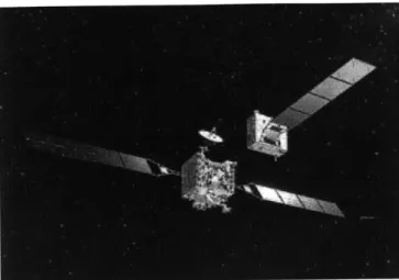
DARPA's Orbital Express Advanced Technology Demonstration (Fig. 1-7), launched in March 2007 and on-going, was the next mission dedicated to autonomous docking demonstrations in space. The goal of the program is to validate the feasibility of robotic, autonomous on-orbit refueling and reconfiguration of satellites to support a broad range of future U.S. national security and commercial space programs [115]. It will demonstrate critical technologies to enable on-orbit servicing systems including standard satellite servicing interfaces, autonomous GN&C systems, autonomous RV, proximity operations, docking, fluid and replacement unit transfer. Multiple docking scenarios with increasing difficulty will be attempted, gradually adding simulated failures to test the system's autonomous fault response capability. Some scenarios will involve an approach along a solar inertial approach corridor (spiral trajectory).
Each of the missions enumerated above involved an increasing level of autonomy. These missions provided valuable experience for future autonomous resupply mis-sions to the ISS like the ones to be performed by the European ATV [32] or the Japanese HTV [66]. Advanced servicing missions like the Hubble Robotic Servicing and Deorbit Mission [18] will also benefit from the experience acquired in these past missions. Table 1.1 summarizes the missions covered in this historical review. It
Table 1.1: Historical review of autonomous docking missions
Mission Year Status Type Anomalies
Cosmos-186, 1967 Success Docking Misaligned capture
Cosmos-188
ETS-VII 1998 Success Docking Thruster anomaly
XSS-10 2003 Success Inspection Navigation problem (confused star tracker), communication interrup-tions
XSS-11 2005 Unknown Inspection Unknown
DART 2005 Failure Inspection Navigation problem (biased veloc-ity measurements), collision
Orbital Ex- 2007 On-going Docking Navigation problem (GPS-based
press system initialization problem)
is important to emphasize that anomalies occurred for each of these missions, with possibly the exception of the XSS-11 mission, which, however, has issued no public report. Moreover, none of the missions mentioned in Table 1.1 involved a tumbling target.
1.3
Previously proposed strategies for docking to
a tumbling target
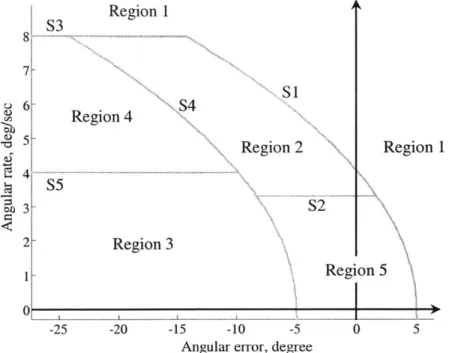
Although no autonomous docking missions to a tumbling target were ever attempted in space, the increasing interest behind satellite servicing missions is forcing engineers to reconsider this possibility. In a recent publication on satellite capturing strategies, Matsumoto et al. [80] presented a classification of different categories of satellite motion with respect to their angular rate and their attitude error. Following this classification, a satellite is considered to be tumbling if its angular rate is between 1 deg/sec and 18 deg/see (3 RPM). Any motion with an angular rate higher than 18 deg/sec is categorized as a spin. The same classification is used below in describ-ing the techniques developed over the years to accomplish dockdescrib-ing with tumbldescrib-ing satellites.
IGLA system could only provide range, range rate as well as bearing angles to the target (pitch and yaw rotation of the line-of-sight to the target). Roll information was only provided when the satellites were in close proximity [4]. Consequently, early control laws, ensuring RV and docking of two spacecraft, were constrained to use only these inputs. Aldrin [9] even proposed control laws using only line-of-sight angular information that can be measured by an astronaut during manned missions. These led to simple docking maneuvers performed in the same orbital plane as that of the target. Typically, the chaser initiated its approach by performing an orbit transfer maneuver from a parking orbit to the target satellite. With both spacecraft set to actively point at each other, the resulting trajectory appeared as docking with a tumbling target (which was actually controlling its tumbling rate). However, indications show that the resulting angular rate for typical orbits was of the same order of magnitude as the orbital rate (~0.07 deg/sec) and driven toward 0 deg/sec at docking [9]. Therefore, such a maneuver does not fall into the category of a docking to a tumbling target as per the classification mentioned above.
In the late 1990's, Tsuda et al. [120, 45] proposed an interesting technique that could allow docking to both spinning and tumbling satellites. They showed that two different spacecraft with the same moment of inertia ratios (MoIRs) can maintain the same rotation pattern without any control torque. Given an inertia tensor I and the
corresponding principal moments of inertia I1, 12 and 13 such that I ;> 12 > 13, the
MoIRs are defined as:
ImaxE Il
/12(.)
Imn 13/12 (1.2)
Figure 1-8 illustrates the proposed strategy for docking and capture. A chaser (the servicing satellite) is composed of long adjustable booms. After estimating the MoIRs and the center of gravity (CG) of the target, it surrounds it in order for its CG to overlap with that of the target, before it matches its MoIRs by adjusting the length and orientation of the adjustable booms. The next step is to synchronize with the
![Figure 1-9: A typical control architecture used for automated docking [40].](https://thumb-eu.123doks.com/thumbv2/123doknet/14732416.573313/48.918.198.730.120.532/figure-typical-control-architecture-used-automated-docking.webp)
![Figure 3-6: Data collected by the U/S sensor system during one sampling cycle [57].](https://thumb-eu.123doks.com/thumbv2/123doknet/14732416.573313/101.918.154.693.117.637/figure-data-collected-u-s-sensor-sampling-cycle.webp)