This is an author-deposited version published in:
http://oatao.univ-toulouse.fr/
Eprints ID: 5395
To link to this article: doi:10.1016/j.rcim.2011.03.004
URL:
http://dx.doi.org/10.1016/j.rcim.2011.03.004
To cite this version:
Desforges, Xavier and Habbadi, Abdallah and
Archimède, Bernard Design methodology for smart actuator services for
machine tool and machining control and monitoring. (2011) Robotics and
Computer-Integrated Manufacturing, vol. 27 (n° 6). pp. 963-976. ISSN
0736-5845
O
pen
A
rchive
T
oulouse
A
rchive
O
uverte (
OATAO
)
OATAO is an open access repository that collects the work of Toulouse researchers and
makes it freely available over the web where possible.
Any correspondence concerning this service should be sent to the repository
administrator:
[email protected]
Design methodology for smart actuator services for machine tool and machining control and monitoring
Xavier Desforges1, Abdallah Habbadi, Bernard Archimède
Université de Toulouse
INPT/ENIT, Laboratoire Génie de Production, 47 avenue d'Azereix, BP 1629, 65016 Tarbes, France
Abstract:
This paper presents a methodology to design the services of smart actuators for machine tools. The smart actuators aim at replacing the traditional drives (spindles and feed-drives) and enable to add data processing abilities to implement monitoring and control tasks. Their data processing abilities are also exploited in order to create a new decision level at the machine level. The aim of this decision level is to react to disturbances that the monitoring tasks detect. The cooperation between the computational objects (the smart spindle, the smart feed-drives and the CNC unit) enables to carry out functions for accommodating or adapting to the disturbances. This leads to the extension of the notion of smart actuator with the notion of agent. In order to implement the services of the smart drives, a general design is presented describing the services as well as the behavior of the smart drive according to the object oriented approach. Requirements about the CNC unit are detailed. Eventually, an implementation of the smart drive services that involves a virtual lathe and a virtual turning operation is described. This description is part of the design methodology. Experimental results obtained thanks to the virtual machine are then presented.
Keywords: machine tool, machining, control, monitoring, smart actuator, multi-agent system
1. Introduction
In the manufacturing context, machine tools can be considered as particular goods. Indeed, they are the products of firms that sell them to other firms for which those machines become productive resources. That is why, on one hand, they have to be designed and manufactured in order to be as customizable as possible to respond rapidly to the customers' demands and, on the other hand, they have to be productive with minimum downtime, flexible and reactive while they are operating in the customers' workshops. The flexibility has been improved thanks to programmable numerically controlled machine tools. The ability to be programmed has contributed to increase the number of types of processes that can be achieved by a machine tool and to increase the geometry complexity of the machined parts.
The productivity, in terms of rapidity, has been improved thanks to the developments of high-speed machining processes. The machine tools that are able to achieve those processes have specific mechanical structures. New functions with adjustable parameters are implemented in their control systems in order to calculate tool trajectories that reduce the effects of undesirable but predictable phenomena that can appear during machining [1]. High speed machining also requires new performances for the computation of the tool paths [2]. The enhancement of productivity can also be obtained by reducing downtime. This reduction is the main goal of OSA-CBM (Open System Architecture-Condition Based Maintenance) project by providing to computerized maintenance and production management systems health assessments of production equipments that combine data on their current health as well as their future health from diagnostic and prognostic treatments [3,4].
Machine tool manufacturers can proposed customized machine tools to their clients by applying modular design to their products. Indeed, the modularity of the structural design of machine tools enables to achieve the combinations of processes expected by the customers and independent controls of spindles and axes motions. The modularity is also a major consideration for the design of their control and monitoring systems for which expected features are scalability, interoperability and portability [5,6]. Object-oriented modeling and programming languages ease the generation of software for such systems because they enable the encapsulation, the specialization, the reuse of functionalities and polymorphism [7,8].
The reactivity is the ability to adapt rapidly to changing environment and it consists in managing freedom degrees of flexible systems. Although the CNC (Computer Numerical Control) machine tools are flexible at the workshop level because of their ability to be programmed, the machine tools become less flexible and therefore not really reactive when the work-piece program is running. Indeed, their monitoring functions often lead to stop the machining operations if an abnormal behavior is detected in order to avoid more damages. Adaptive controls are solutions to counter the changes of the machining process parameters like tool wear, depth of cut, vibrations, etc., but they are often very dedicated. Indeed they can keep the cutting force constant or aim at reducing vibrations [9,10].
In order to ease the integration of new functionalities, open and/or modular architectures of CNC have been developed [5,11,12] as well as integration frameworks and languages for distributed computer systems [13]. The development of open architectures of CNC is also guided by requirements in terms of agile manufacturing that lead to the integration of the CNCs of the machine tools to the CAD-CAM systems [14,15] and even in terms of remote manufacturing [16]. Frankowiak et al. [17] analyze in their review paper on microcontroller-based machine and process monitoring several eligible architectures.
Nevertheless, those architectures exploit the computational abilities of the CNCs. Indeed, the added functions are implemented in the CNC or in, other platforms that perform completely or partially the added functions that communicate their results to the CNCs. In such architectures, the CNCs are still the lowest decision centers of the manufacturing systems. Wang [14] proposed an integrated design-to-control holonic manufacturing systems where intelligent sensors/actuators are mentioned. Even if the use of smart or intelligent sensors/actuators enables to add a new decision level closer to the process thanks to their computational abilities, they are quite never considered although this contributes to the improvement of the reactivity of the manufacturing system [18].
The main goal of this paper is to propose a design methodology of smart drive services for CNC machines to enhance, for the machine manufacturers, the modularity and, for the machine users, the productivity and the reactivity. The proposed design methodology exploits the object oriented approach and joins the smart actuator concept, which is firstly presented as well as its underlying functionalities. Although the smart actuators enable to improve performances that are listed in this paper, they do not contribute to the improvement of reactivity at machine level. This improvement requires the capacity of managing freedom degrees at the machine level. The multi-agent system approach enables such a management aiming at predefined objectives that may vary according to the requirements of the machining processes. That is why the proposed design extends the smart actuator with the notion of agent, which also satisfies the need of modularity. The paper then presents the description of the services of a smart drive, the interactions between the smart drives and the CNC unit and underlying requirements for the CNC unit. The last part is dedicated to the presentation of an implementation that is also the methodology guidelines. The aim of this implementation is to controls and to monitoring a virtual CNC lathe and a virtual turning process. The treatments of the proposed services are detailed for this application and results obtained thanks to the virtual machine and process are given.
2. Smart actuator concept
The smart or intelligent sensor and actuator concepts were defined in the 1980s. They address the lack of reliability in complex systems inherent to the numerous sensors and actuators needed for their control and monitoring. The proposal of this concept consists in adding information processing and bi-directional communication abilities to the main service functions of sensors and actuators [19,20]. Of course, the concept also took advantage of the emergence of field buses (CAN, FIP, Profibus, etc.). The smart instruments also contribute to the distribution of data processes and of data bases closer to the physical process. That decentralization improves the modularity of the systems. Indeed, it enables to update or to
replace local devices with only minor actions on some other components (e.g. to set up a new device in the bus manager).
The information processing ability is mainly used to implement functions dealing with: measuring to transform physical values into computable data,
elaborating reliable data as close as possible to the real situation to send them to the other devices of the system.
monitoring and diagnosing to provide data dealing with the health status of the smart actuator and of the part of the physical process on which it operates,
acting safely to make decision about actions to do that correspond to the real situation and to predefined objectives,
communicating to send data, like health status, to other devices of the system and to get data, like objectives, from other devices of the system,
managing the internal application and data base.
Those functions provide various services. Elaborating reliable data mainly deals with data validation that improves the metrologic quality of measurements. Monitoring and Diagnosing provide data about the health status of the actuator; those data become decision supports for various purposes:
the maintenance management to plan, to prepare and to do the maintenance actions,
the production management to plan production knowing the availability of the production resource, and to act safely.
'Acting safely' reinforces the system safety and reliability by adapting to the situations observed by monitoring and diagnosing functions whom information are processed from validated measurements. 'Communicating' enable the necessary data exchange between the various devices of the productive resource [21].
In most cases, the studies carried out in the field of smart actuators are led to develop actuators dedicated to the achievement of a specific function of a given kind of system [22,23,24]. However, the use of smart actuators is not entirely satisfying. It is especially the case for the reaction to disturbances mainly because their behaviors are strongly predetermined like in the particular case of adaptation techniques that aim at keeping constant the cutting forces [9,10]. Those adaptations are specialized and do not entirely match flexibility requirements.
3. Adding agent abilities to smart actuators
In order to improve the flexibility of adaptation functions, freedom degrees must be created at the ma -chine level. The management of those freedom degrees requires decision-making abilities carried out by the smart actuator. In that way, those smart actuators are able to react rapidly when they detect a disturb -ance by making the appropriate decision according to defined goals and boundaries. The detection of disturbances or the detection of situations that do not lead to the satisfaction of the defined goals require co -operation between the smart actuators because they all contribute to the achievement of the process, as well as they require cooperation between them and the CNC unit, which can be considered as a supervisor [18].
Smart actuators with decision-making abilities can be considered as agents according to the definition of a computational agent given by Jennings and Wooldridge [25] where an agent is defined as a self-contained problem-solving computational entity able, at least, to perform most of its problem-solving tasks, to interact with its environment, to perceive its environment and to respond within a given time, to take initiat -ives when it is appropriate. Indeed, measuring and acting are the main solving-problem tasks; measuring, cooperating and communicating are the perception and interaction abilities; making decisions can be con-sidered as a way of taking initiatives.
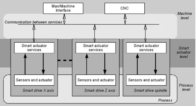
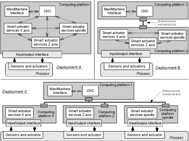
In the proposed design, the functions are computational services provided by the smart actuators or by cooperation between the smart actuators and/or the CNC unit. This integration makes it possible the software architecture shown in Fig. 1 [18]. From this software architecture, several deployments are possible for the services provided by the smart actuators. Three deployments are proposed in Fig. 2. The CNC unit often achieves the man/machine interface. The smart actuator services can be implemented in the CNC computing platform (Deployment A in Fig. 2), in a unique unit dedicated to the implementation of the services of all the smart actuators (Deployment B in Fig. 2), in several units (Deployment C in Fig. 2). Other deployments may be suitable too. The communication between the smart actuator services and the CNC unit services may be carried out thanks to a middleware, like CORBA, COM/DCOM, that ease the achievement of the communication between the computational objects providing the services.
4. Services of a smart drive
Four operational services are carried out by the smart drives that enhance traditional abilities of machine tool drives that are measuring and acting. Those services are data validation, drive monitoring and diagnosing, process monitoring and adapting.
4.1 Data validation
The data validation activity is a major functionality of smart instruments. It generates credible, reliable and representative information of the measured physical variables. Those measured values are the input of the other services of the smart drive. Therefore, the enhancements of the metrologic quality of the measurements or the association of specific values to the measurements that indicate the trust in the measured values reinforce the trust in any piece of information that is then computed from the measurements. The methods to validate measurements are numerous in the literature. The data validation activity can therefore be implemented, by correcting the measured values by measured influence values, by material redundancies, by analytical redundancies or by the use of other methods based on various techniques like artificial neural networks [26]. Often, those techniques of data validation make it possible to isolate faulty sensors. This isolation ability contributes to the drive monitoring and diagnostic service.
4.2 Drive monitoring and diagnosis
The drive monitoring and diagnostic service provides the health status assessment of the drive. The health status of the machine tool, which gather the health status of its drives is helpful for condition based maintenance and production planning to make decision about maintenance actions and production tasks. The monitoring main objective consists of fault detection and isolation whereas the diagnosis main objective consists in identifying the origin of the fault that often leads to list faulty components. Therefore, the diagnostic service is a sort of client of the monitoring service.
The techniques that enable to carry out the monitoring service are numerous [3,4]. They mainly compute relevant indicators from measurements. Those indicators can be measured physical values, state observers, residuals, identified structural or physical parameters, statistical values… that are compared to theoretical boundaries thanks to tests of hypotheses, like the Wald test, that enable to make decision about the presence of faults and their isolations [27].
The technical diagnosis mainly consists of a pattern recognition problem. That is why many technical diagnostic functions are based on artificial intelligence techniques like expert systems, neural networks [4]…
4.3 Process monitoring
The process monitoring service consists in detecting faults during the machining operations. Considering the metal removal processes, like turning or milling, faults that affect those processes and may damage
work-pieces are mainly due to tools if there is no fault of metal removal assistance system. Those faults are phenomena like tool wear and tool breakage that may also be a consequence of tool wear. The literature is very rich in the field of tool wear and/or tool breakage monitoring [28,29]. Those monitoring techniques can then be exploited in order to stop the process, when the tool is worn or when it breaks, or to adapt on-line or off-line the process parameters to the tool wear.
Techniques that require specific sensors do not exactly fit in the proposed design of smart drive because they are very dedicated and they so require specific data processes that do not involve any kind of cooperation. Indeed, they directly send their results of their monitoring processes. However, the techniques based on indirect measurements, like current and voltage, seems to be more relevant. Indeed, they can be distributed into several computational objects that can so cooperate to achieve the process monitoring service by exchanging and processing data. In that particular case, the process monitoring service provided by a smart drive requires cooperation with the other smart drives because each smart drive only monitors a part of the process.
4.4. Adapting
The objective of the adapting service is to keep on machining with often lower performances to take into account the machine tool health status and/or the machining process status especially the tool wear in the case of a metal removal processes. With such processes, the adaptation often leads to modify the cutting speed, the feed speed, the position of the reference point of the cutting tool to obtain the expected surface. However, the adaptation may also consist in modifying the parameters or the structure of regulators of drives [30,31]. The adaptation may require communication between the smart drives. For example, if the adaptation requires a modification of the feed speed, the adaptation of the motion speeds of all the drives that carry out the machining process is necessary in order not to modify the tool path.
4.5 Requirements for the CNC units
The implementation of smart drives generates requirements for the CNC units design.
The CNC unit must be able to make decision from the monitoring data provided by the smart drives. The decision making can only be to valid the adaptation proposed by the smart drive according to objectives or to stop the machining operation if the integrity of the machine tool or of the work piece may be endangered.
According to the process monitoring method, the CNC unit may have to provide data to the smart drives. The example of an implementation of the proposed smart drive services illustrates this last requirement
by providing the depth of cut that can be computed from a raw part model and the position of the cutting tool.
An interface is necessary to enable maintenance operators to check the monitoring data of the smart drives or to setup the smart drive. This interface can be set into operation by the CNC unit or by another system but this may be more costly.
However, the descriptions and the goals of those services are not relevant enough, modeling is therefore necessary.
5. Smart drive services modeling
UML 2 (Unified modeling Language) is an object oriented modeling language that enables modelization according to functional, informational and behavioral views. UML 2 proposes thirteen kinds of diagrams to specify or to model like: state machine diagrams that describe the states of objects may be in, as well as the transitions between those states, activity diagrams that are the equivalent of flow charts and data flow diagrams (DFDs), sequence diagrams that are used to model sequential logic via the ordering of the messages [32].
The object-oriented approach enables to handle concepts like inheritance, polymorphism, abstraction, encapsulation... [7]. Those features enable to consider at the same time various types of drives like spindles and feed-drives equipped with DC motors or AC motors for various types of machine tools like milling centers, lathes... The object-oriented approach enables to define common interfaces for services that are implemented according to each technological feature of the drives, of the machine tools and of the machining processes.
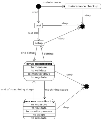
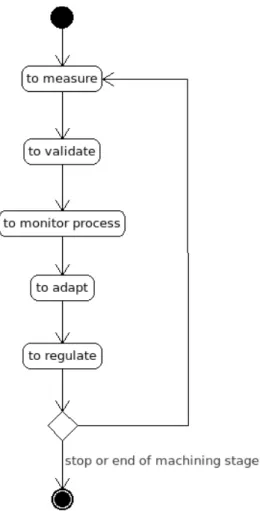
The description of the smart drive general behavior is made of two main states that are represented in the state-transition diagram of Fig. 3: drive monitoring and process monitoring. State-transition diagrams are often used to describe the behavior of objects that belong to a particular class. A state is represented by a box and a transition by an arrow. Other labels may figure inside the boxes above the state name those labels are the names of the activities that are processed during the state. The drive monitoring state and
process monitoring state are separated because it is difficult to carry out the machine monitoring and the
process monitoring at the same time particularly when machine and process are monitored from the same measurements. Generally, the degradations of the machining process vary more rapidly in time than the degradations of the machine. For example, the effects of tool wear appear much more rapidly than the effect of guide ways wear (from few minutes to few hours vs from few days to few months). If the machining operations are not too long, the separation of those two states is then possible.
The drive monitoring and the process monitoring states are made of common activities that are:
to measure that consists in processing the measured physical values in order to make them computable,
to validate that is described in section 4.1,
to regulate that consists of the control task of the servo drive aiming at acting according to a given reference.
The specific activities of the drive monitoring state are to monitor process and to adapt. The specific activities of the process monitoring state is to monitor drive. Those activities are described in section 4. The CNC unit sends messages containing the events: start, stop, machining stage and end of machining
stage from the data of the work-piece program. Those events lead to the change of state of the smart
drive.
The three other states: test, setup and maintenance checkup are also presented in Fig. 3.
test consists of the verification that the smart drive is ready to receive message, it only sends a message: a “heart beat” to the CNC unit, the CNC unit then sends a message that corresponds to the setup event if all the smart drives have sent their “heart beats” within a given time after the
start event. Otherwise, the CNC unit send a stop message.
setup consists, for the smart drive, in receiving messages from the CNC units that contains various parameters. Those parameters are then used for regulation, adaptation or monitoring purposes.
maintenance checkup consists of a dialog during which the smart drive sends data (parameters, thresholds, faults, diagnosis...) on demand to a device and it can receive new values for its parameters, thresholds...
The modifications of the smart drive data must pass an authentication procedure to warrant the machine tool safety.
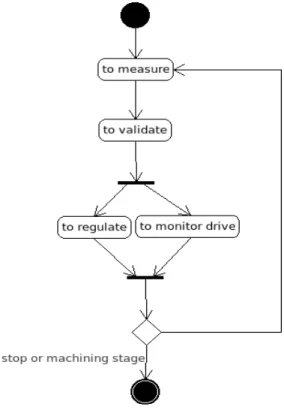
The activity diagram of the drive monitoring state is presented in Fig. 4. An activity diagram is generally used to describe the sequence of activities that are operated during a given state where an activity can be considered as a non-interruptible routine. Boxes represent the activities whereas the arrows represent the transitions between the activities. Flows can also be added between activities [32]. The sequence of the activity diagram is here processed for each sampling period while the smart drive does not receive any message from the CNC unit containing the events stop or machining stage. The activities to regulate and
to monitor drive do not need to be carried out a parallel way. Therefore, any sequence of those activities
of the activity to regulate. The reference may also be sent before the activity to measure. In some particular cases like robot arms, communication may be required between the smart drives to achieve the activity to monitor drive. Indeed, the positions, the speeds and the accelerations of the operative parts of the other smart drives must be provided in order to define loads due to their weights and moments of inertia that may affect the dynamic of the considered smart drive. The activity to monitor drive will send a message to the CNC unit if it detects a fault. If a fault is detected, a diagnostic function will be computed in order to identify the faulty components of the smart drive.
The activity diagram of the process monitoring state is represented in Fig. 5. Like in the drive monitoring state, the sequence of the activity diagram is processed for each sampling period while the smart drive does not receive any message from the CNC unit containing the events stop or machining stage. In this state, to regulate is the last activity of the sequence. Indeed, the activity to adapt needs the data dealing with the process monitoring in order to make decision about the proper adaptation. This adaptation may need cooperation between the smart drives. For example, if one smart drive decide to reduce the feed speed the other smart drives involved in the work-piece geometry must reduce their speed in the same proportion. The adaptation may also change the values of the regulator or change the structure of the regulator.
to adapt is therefore an activity that requires communication between the smart drives. During this
activity, each smart drive proposes an adaptation according to the data generated by its to monitor process activity and its own abilities in terms of speed, power... The applied adaptation is then decided from predefined goals and the abilities of the smart drives. This activity manages the freedom degrees at the machine level and it is also the kernel of the decision center of the smart drives.
The described activities carry out the services of a smart drive. The following section is dedicated to an implementation of the proposed smart drive services for a lathe and a turning process and to the presentation of the methodology that leads to bring those services into operation.
6. Implementation
The presented case study for the implementation of smart drives services consists in an application to a lathe and a turning process. The lathe is a virtual machine tool made of two axis feed-drives and one spindle for the operative part. This virtual machine tool enables to simulate the dynamics of the control, the electrical and mechanical components and the machining process simultaneously. According to the conclusion of Jönsson et al. [33], virtual machine tools makes it possible to assess systems design
suggestions at an early stage of development. The smart drives services are then implemented for each one of the three virtual drives according to the general design described in section 5. The command part is completed by a computational object whose role is to the simulate the CNC unit that calculates and sends the references to the spindle and to the feed-drives from the work-piece program and that cooperates with the three smart drives. Each smart drive achieves its activities according to its state. The implementations of the activities are highly dependent of the machine tool design and of the machining process. The following descriptions of the activities can be considered as a methodology to design the smart drive services although those services are designed according to the particularities of one machine and its process. Indeed, the methodology present the considerations that lead to a specific design of a smart drive services from the proposed general smart drive modeling. The activities that are considered in this section are the ones carried out during the states drive monitoring and process monitoring.
6.1 to measure
to measure is the activity that will provide intelligible data to the other activities. The choice of physical
values to measure depends on the treatments of the other activities. Nevertheless, the proposed implementation aims at reducing the smart drive cost by minimizing the number of sensors or of specific and costly sensors. That is why, the two monitoring activities use the same measurements that are the voltage, the current and the speed in this implementation. For real implementation, redundant sensors may be added for data validation purpose. However, voltage, current and speed sensors are not very costly. During this activity, the sampling period of the analog-digital converters are adjusted according the sampling period provided by the CNC unit for real implementations.
6.2 to monitor drive
DC motor drives are considered for the feed-drives and the spindle. Here, the monitoring is based on the measurements of voltage, current and speed and consists in estimating the physical parameters of the drive that can easily be associated to faults [19]. This eases the design of a diagnostic function (see Table 1), which is not developed here. Among diagnostic techniques that exist in the field of DC motor diagnostic let us note the one presented in [34].
Considering DC motor drives with permanent magnets, the estimated parameters are, the inductance L, the resistance R, the torque or counter electromotive force constant K, the total moment of inertia on the motor shaft J, the viscous friction coefficient considered on the motor shaft V and the dry friction torque on the motor shaft D. A behavioral model of such drives is given by the following equations:
u − K . w=L . ˙i +R . i (1)
K . i− l=J . ˙w +V . w+D . signw (2)
where u is the voltage, i the induced current, w the motor shaft angular speed and l the load torque on the motor shaft that depends on the cutting force. Several methods can be implemented to estimate of physical parameters of continuous models like the one made of the relationships (1) and (2). The method implemented in the experimental platform consists of one same low pass filtering for all the signals as described by equation (3) for a signal x:
xf=
1
1 +Tsx (3)
where s is the Laplace operator and xf the filtered signal. In equation (1) and (2), the filtered signals replace the non filtered ones and their derivatives ˙xf are replaced by:
˙xf= x−xf
T (4)
The implemented estimator is the recursive least squares algorithm, which is initialized with the nominal values of the parameters. The parameters of the equation (1) are estimated before the ones of equation (2).
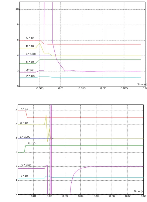
to monitor drive is processed while there is no machining process so l=0. An example of the estimations
of the physical parameters is given in Fig. 6 for the parameter values that are given in Table 2. The spindle and the feed-drives are supposed to have the same physical parameter values in the experimental platform. The curves of the estimated parameters converge within 0.2 s. If the period without machining process is longer it could be used to compare the behavior of the drive with its estimated model. The discrepancy between the drive behavior and its model behavior can then be analyzed in order to detect backlashes [35]. The monitoring of the static converter associated to the DC motor is not implemented. Nevertheless, works dealing with fault detection of such equipment exist like the ones presented in [36,37].
6.3. to monitor process
The estimation of cutting tool wear is useful to avoid tool breakages that often definitely damage the work-piece. The objectives of this estimation can be either the on-line tool path correction to take into account the changes of the tool geometry, this correction is not implemented in the presented case study, or the verification that the cutting tool can achieve the machining operation. Therefore the process monitoring consists of the tool wear estimation. This estimation can be based on cutting force that
generates load torques onto the motor shafts. The load torque can then be estimated from current, and speed measurements [29]. Indeed, the load torque l on a motor shaft is a function of the cutting force generated by the machining process. l can be estimated from the equation (2). Knowing l and the reduction ratios of the gears and of the ball screw and nut system, the cutting force component applied on the drive can be estimated. This estimation needs the measurements of i and w and the more recent estimated values for the parameters K, J, V and D. The cutting force depends on the cutting parameters (cutting speed, feed speed and depth of cut and, for milling operations, the number of cutting edges in the part as well as the angular position of the spindle) but also on the wear of the cutting edge(s) [38,39]. Two models are therefore necessary:
one model that sets the relationships between the cutting force components and the cutting parameters,
one model that sets the relationships between the variation of cutting force components and wear under given cutting parameters.
The considered turning operation is described in Fig. 7.
The considered model of the cutting process is empirical and described in [39]. According to the notation of Fig. 7, the relationship (5) with i = t,l or r establishes the model of the cutting process:
Fi=Ki. Cspi. Fsqi. Dcri (5)
where Cs is the cutting speed, Fs is the feed speed, Dc the depth of cut and, Fi is the magnitude of the cutting force component, pi, qi and ri are empirical coefficients and Ki is a coefficient that varies with wear. Ki is considered as a constant in the theoretical model processed by the smart drive service. The force component that is estimated that way is denoted Fmi.
The models and their coefficients are sent by CNC unit to the smart drives before each machining operation.
To estimate Ft, the spindle smart drive requests the X axis position of the tool from the X axis smart drive. The X and Z axis smart drives compute directly the estimated Fr and Fl from (2), with their latest estimated physical parameters, and their reduction ratios. Then, the smart drives compute the cutting force component from the equation (5). Those computations need data exchanges between the smart drives and the CNC unit to define Dc, Fs and Cs. The computation of Dc is made by the CNC unit. It requires the position of the tool in the X and Z axes but also a geometrical description of the work-piece before the machining operation. This leads to new requirements for the CAD-CAM system and the CNC unit. They consist of the geometrical descriptions of the work-piece before the machining operation and after the
machining operation from which the CNC unit has to compute the depth of cut. Therefore, these two models have to be available for the CNC unit before the machining operation. This computation is not detailed further in this paper. The sequence diagram that models those communications is shown in Fig. 8 where horizontal arrows depict the messages. Then, each smart drive computes the tool wear Wi it estimates from Fmi, from Fi the cutting force estimated from its load torque and (2) and from the ratio (6)
Wi= Fi
Fmi (6)
The Wi are then sent to the CNC unit that decides to stop the machining operation if at least two values of
Wi are over a given threshold.
6.4. to adapt
The activity to adapt is dedicated to the management of freedom degrees at the machine level. Those freedom degrees can consist ofpossible choices of regulator structures, regulator parameters or cutting parameters. The adaptation techniques that consist in modifying the structure or the parameters of the regulators enable to adapt the behaviors of systems to disturbances (like the changes of the drive parameters) in order to respond as well as possible to the references. In this case, the smart drives do not need to cooperate. Indeed, they will adapt their regulators according to the disturbances they detect thanks to their monitoring activities. This kind of adaptations does not act onto the variables of the cutting process that are the cutting speed, the feed speed and the depth of cut. Although the implementation of the adaptation of the regulators has not been implemented at this stage of development, the accommodation of the references, that the CNC unit sends, enables to change the variables of the cutting process.
The management of those changes requires freedom degrees. The tool manufacturers often define minimum and maximum values for cutting speed, feed speed and depth of cut for a given tool which is generally designed for a group of machining operations and a group of machined materials. Within those boundaries the cutting process operates correctly. Therefore, the freedom degrees consist of possible choices of cutting speed and feed speed within those boundaries.
The freedom degrees are managed according predefined objectives. The main objective is to machine good quality parts with the highest possible productivity. Once the cutting process and the tool are chosen, the quality of the part mainly depends on:
the mechanical structure of the machine, of the fixture and of the tool (elasticity of the mechanic-al structure and of the tool, backlashes between moving parts…),
the cutting parameters (cutting speed, feed speed, depth of cut),
the way the CNC unit calculates the trajectories from the work piece program describing the tool path.
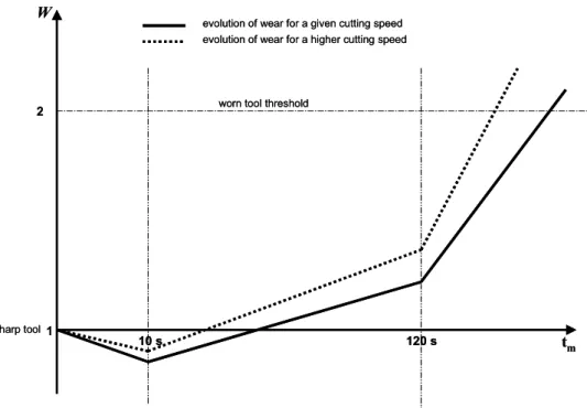
The productivity consists in manufacturing as many parts as possible in a given time at the lowest cost. Therefore, the feed must be as rapid as possible with respect to the specified allowance of the cutting parameters and within the machine capacity (maximum power and maximum current). Increasing the tool life saves time and money. Indeed, the costs relative to tooling are reduced when a same tool can be used to machine more parts; it also reduces the number of tool exchanges that are non-productive operations. The tool wear profile that is simulated by the virtual lathe is presented in Fig. 9.
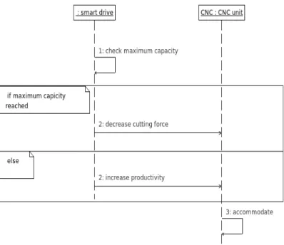
It varies in time and also increases with the cutting speed. Therefore decreasing the cutting speed and increasing the feed speed, increase the productivity but also the cutting force that must not lead to the violation of the maximum current or power of the spindle and of the feed drives. Firstly, the accommodation simultaneously aims at decreasing the cutting speed and at increasing the feed speed. When one smart drive reaches its maximum capacity (power or current), the accommodation then consists to increase the cutting speed and when this becomes not possible, because the maximum cutting speed is reached, it decreases the feed speed while it does not reach the minimum feed speed otherwise the machining operation is stopped. Of course, this accommodation strategy mainly depends on the way the tool wear evolves according to the cutting speed and feed speed and also depends on its ability to warrant the expected roughness of the machined work-piece surface. This accommodation may so be suitable for roughing down and semi-finishing work-pieces. Nevertheless, this accommodation strategy must be disabled for finishing work-pieces particularly if regular surface roughness is expected.
The accommodation strategy is achieved by the CNC unit that changes those values at the next sampling step from the messages it receives from the smart drives that tell if they reach their maximum power or their maximum current or if they do not. Those messages are decision reports of the smart drives that request the reduction of the cutting force or the increase of the productivity. The CNC unit, which receives those messages from all the smart drives, makes the final decision. The sequence diagram presented in Fig. 10. shows the data exchanges between the smart drives and the CNC unit.
The changes of cutting speed, which is obtained by the spindle speed, consist of steps of ±0.1 % of its nominal references. The changes of feed speed, which is obtained by the combination of the feed drives speed, consist of a modification of the nominal sampling period by steps of ±0.1 % of the position references that must be the same for the feed drives and the spindle. The sampling period must so be a parameter that the CNC unit sends to the smart drives (the spindle included). This modification of the
sampling period is only possible if the new sampling period is a multiple of the minimum sampling period of the real analog-digital converters for the measurements and the real digital-analog converters for the commands that the smart drives send to their static converters.
6.5 to validate
All the activities of process monitoring and drive monitoring states exploit at least one of the measurements of current, voltage and speed. It is therefore necessary to validate those measurements to reduce the risk of non detection or false detection of the monitoring activities that leads to make bad decision. Considering DC servo motor drive, it is possible to validate those data by adding at least one redundant current sensor and one redundant voltage sensor. Generally, DC servo motor drive are equipped with one tacho-generator used to measure its rotation speed and the feed drives are also equipped with a position sensor whose derivative value enable to obtain its rotation speed knowing the reduction ratio. In order to make decision about a faulty sensor, an estimated value of current, voltage or speed is obtained from the two other ones and the equation (1) with the latest estimated parameters. It is possible to obtain at least a second estimated value for current, voltage and speed because two measurements for each of them are available.
The validation scheme is presented in Fig. 11 for current measurement, where ii are the current measurements, wi are the speed measurements and ui are the voltage measurements. The same scheme is obtained for the two other ones by circular permutation. The validation enables to correct the measurement and to isolate faulty sensors. A faulty sensor is isolated if its measurement is too far from the mean of the majority of the measurements or estimations.The fault of the sensor is logged locally and/or sent to the maintenance management. However the machining operation can go on while there is at least one valid sensor and one valid material or analytical redundancy for each measurement. In that case, faults of sensors are masked because the measurements of faulty sensors are not used. If the condition of two valid redundancies at least is not fulfilled the machining process is stopped and a message is sent to the maintenance management.
Then, only the measurements are compared to the other valid measurements or valid estimations that are not considered faulty and they are corrected the following way but only during the drive monitoring state. Let us note mr the true value, mm the measured or estimated value, g the gain (there is a gain error if g≠1) and b the bias (there is a bias error if b≠0).
mr is unknown but we assume that it is the measurement or the estimation with which mm is compared to. Then g and b are estimated thanks to the recursive least squares algorithm, which is initialized with the values of g and b that were estimated during the previous drive monitoring state. This validation structured has been tested thanks to a physical test bed of DC motor drive. They are presented in [40]. g and b are estimated for each valid measurement or estimation. Therefore a set of estimated parameters
gmr and bmr is obtained. The corrected value of the measurement mc is obtained from one of the
valid measured values mm, from the mean values of gmr and bmr noted gm and bm computed from the valid measurements or estimations and from:
mc=mm−bm
gm (8)
During the drive monitoring state, the corrected values of the measurement are computed from the values of gmr and bmr that were estimated during the previous drive monitoring state, from the valid measurements and estimations and from (8). At the end of the drive monitoring state, the values of gmr
and bmr are updated.
During the process monitoring states, the detection of faulty sensor is computed, and the corrected values of the measurements are computed from the values of gmr and bmr that were estimated during the previous drive monitoring state, from the valid measurements and estimations and from (8).
6.6 to regulate
The main task of this activity consists in carrying out the regulation of the operative part of the smart drives. During this activity, the sampling period of the digital-analog converters is tuned according to the value that the CNC unit sends.
The regulation schemes of the drives of the virtual lathe are presented in Fig. 12 for the spindle and in Fig. 13 for the feed-drives. Those regulations are made of imbricated control loops for current, speed, and, in the case of the feed-drives, position.
This activity may also tune the regulator parameters or change the regulator structure according to what was decided by the activity to adapt.
The virtual lathe is developed in C++, which is an object oriented programming language. It simulates the regulated feed-drives and spindle as well as the machining process according to the described wear evolution the virtual lathe. It also implements the activities to measure and to regulate for each smart drive. Indeed the virtual machines make it possible to set and/or to get numerous data like variables and parameters. An other distributed computational platform brings into operation five computational objects: the spindle, X axis and Z axis smart drives services as well as one CNC unit according to the specifications of sections 5 and 6. The to validate activity of the smart drives, which requires redundant current and voltage sensors, is not implemented in the experimental platform. Indeed, it would not be very relevant because the signals are the results of computations of the virtual lathe and so they are not perturbed.
The five computational objects and the virtual lathe are distributed on computers that communicate thanks to an Ethernet network and CORBA. CORBA is a middleware that provides facilities for the communication between distributed entities. It is based on the client/server approach. This offers a standard and open communication system [41].
The considered turning operation is described in Fig. 14 which is virtual too. The raw part diameter is 402 mm; the final diameter is 400 mm; so the depth of cut is 1 mm. The length of the machined cylinder is 150 mm. We assume that the nominal feed speed is 5 mm/s and the nominal cutting speed is 10 m/s, which corresponds to 49.9 rad/s for the spindle speed. The only segment involved in metal cutting process is the bloc 5. We have considered a quite large tool clearance that may represent the necessary space to load the raw part and to unload the machined part. Blocs 1 and 2 describe the tool path after setting the part origin. The tool follows the segments of those blocs only once before starting the turning operation of the first part. During the simulations, the machining process is simulated from model (5) and the values of the coefficients are the following ones:
pi=−0. 1 qi=ri= 1 Kt=4e7
Kr=Kl=2e7
(9)
Those values have been chosen in order to generate force components Fi that lead to reach the maximum power or current of one drive at least because of the increasing tool wear.
Two scenarios are compared thanks to the virtual lathe and the distributed computational platform. The first scenario is obtained by disabling the to adapt activities of the smart drives as well as the effect of the messages sent by their monitoring activities. So the simulated behavior corresponds to the standard
functioning of a traditional CNC machine tool. Nevertheless the messages that the monitoring activities send are logged. The second scenario is simulated with to adapt activities enabled. Some effects of the messages sent by the monitoring activities are sometimes disabled but logged. In this scenario, the cutting speed and feed speed are supposed to vary within an interval of more or less 20% around their nominal values. All the servo-drives have the same parameters. For the axis feed-drives, the maximum power is 6 kW and maximum current is 50 A whereas the maximum power is 12 kW and maximum current is 100 A for the spindle. The power and the current consumed by a servo-drive depend, for a constant load torque, on its physical parameters.
Considering the first scenario, the simulations show that the machine tool achieves 6 parts, the smart spindle reaches its maximum capacity during the machining of the 7th part and the tool reaches its wear threshold during the machining of the 8th part. Estimations of the tool wear that are computed according to the specification presented in section 6.3 are shown in Fig. 15 for the first part. These estimations are quite accurate because there is no bias in the estimations of the physical parameters and because all the models (raw part model, cutting process model…) computed by the smart drives correspond exactly to the ones run by the virtual lathe. Indeed the relative error is about 1E-3. The sign and the magnitude of the relative errors change with the variation ratio of the wear. We therefore suppose that the errors of estimation are mainly due to the delay to compute the estimation of W that is provided for the next sampling period. Those simulations show that the machine tool should stop after 221.55 s of operation because the smart spindle reaches its maximum capacity (at this time W is estimated at 1.685) and that the tool is worn (W=2) after 258.44 s of operation.
Considering the second scenario, the simulations show that the machine tool achieves 8 parts. The tool is worn (W=2) during the machining operation of the 9th part after 257.38 s of operation whereas the to
adapt activities of the smart drives and the CNC unit still decide to reduce the feed speed (Fs) to make the smart spindle operate under its maximum capacity.
The comparison between those two scenarios shows that the monitoring and adapting activities of the smart drives enable to increase the number of machined part with a same tool (from 6 to 8 in that particular case). It also reduces the mean time to process one part (≈4 s in that particular case). The five computational objects and the virtual lathe have also been implemented in a same computer with the same results. This denotes that the smart drive services do not overload the computer and that the deployments shown in Fig. 2 are possible.
8. Conclusion
The proposed software smart drive services have been successfully tested thanks to a virtual lathe and a computational platform excepting the measurement validation treatment that has been tested separately thanks to a test bed. The services of smart drives enable to carry out functions for monitoring, diagnosing and adapting. Every piece of information is processed from current, speed, voltage and position measurements that are already achieved in CNC machine tools for regulation purposes. The only additional sensors would be current and voltage sensors for processing measurement validations. The various functions share data. For example, the physical parameters are estimated for monitoring and for diagnosing the servo-drives, for estimating the cutting force and the tool wear and for validating the measurements. This avoids redundant data processes that may be encounter in the implementation of function dedicated modules.
The simulation results show that the management of freedom degrees at the machine level by the smart drives and the CNC unit according to data, which are elaborated by monitoring activities, increases the tool life and the productivity. Further developments in the field consist in implementing smart drives into a real machine tool in order to valid the results obtained by simulations.
Other developments consist of the development of libraries in order to propose implementations of monitoring and adapting activities for various kinds of servo drives (e.g. equipped with AC motors) and processes (milling, drilling...). Those developments also include the development of functions dealing with the adaptation strategy according to the evolution of tool wear that mainly depends on the cutting and feed speeds. Those libraries could then form a framework to design smart drives services for machine tools and so ease their developments and customizations.
Eventually, the smart drive services shall be integrated to production and maintenance management systems in order to plan manufacturing and maintenance operations according to the machine and process monitoring data the smart drives provide.
Acknowledgements
The authors would like to thank the European Commission and the partners of the Innovative Production Machines and Systems (I*PROMS) Network of Excellence for their support.
References
[1] D. Renton, M.A. Elbestawi, High speed servo control of multi-axis machine tools, International Journal of Machine Tools & Manufacture 40(4) (2000) 539-559.
[2] R.A. Osornio-Rios, RdJ. Romero-Troncoso, G. Herrera-Ruiz, R. Castaneda-Miranda, Computationally e cient parametric analysis of discrete-time polynomial based acceleration–deceleration profileffi generation for industrial robotics and CNC machinery, Mechatronics, 17 (2007) 511-523.
[3] R. Kothamasu, S.H. Huang, W.H. Verdun, System health monitoring and prognostics – a review for current paradigms and practices, International Journal of Advanced Manufacturing Technology 28 (2006) 1012-1024.
[4] A.K.S. Jardine, D. Lin, D. Banjevic, A review on machinery diagnostics and prognostics implementing condition-based maintenance, Mechanical Systems and Signal Processing 20 (2006) 1483-1510.
[5] S. Schofield, P. Wright, Open architecture controllers for machine tools, part 1: design principles, Journal of Manufacturing Science and Engineering 120 (1998) 417-424.
[6] M.G. Mehrabi, A.G. Ulsoy, Y. Koren, P. Heytler, Trends and perspectives in flexible and reconfigurable manufacturing systems, Journal of Intelligent Manufacturing 13 (2002) 135-146.
[7] M. Blaha, J. Rumbaugh, Object oriented modeling and design with UML, second ed., Prentice Hall, 2005.
[8] A. Molina, C.A. Rodriguez, H. Ahuett, J.A. Cortes, M. Ramirez, G. Jimenez, S. Martinez, Next-generation manufacturing systems: key research issues in developing and integrating reconfigurable and intelligent machines, International Journal of Computer Integrated Manufacturing 18(7) (2005) 525-536. [9] Y. Liu, T. Cheng, L. Zuo, Adaptive control constraint of machining process, International Journal of Advanced Manufacturing Technology 17 (2001) 720-726.
[10] Y.H. Peng, On the performance enhancement of self-tuning adaptive control for time-varying machining processes, International Journal of Advanced Manufacturing Technology 24 (2004) 395–403. [11] Y. Altintas, N. Newell, M. Ito, Modular CNC design for intelligent machining, part 1: design of a hierarchical motion control module for CNC machine tools, Transactions of the ASME, Journal of Manufacturing Science and Engineering 118 (1996) 506-513.
[12] C.H. Yeung, Y. Altintas, K. Erkorkmaz, Virtual CNC system. Part I. System architecture, International Journal of Machine Tools & Manufacture 46 (2006) 1107–1123.
[13] D. Li, F. Li, X. Huang, Y. Lai, S. Zheng, A model based integration framework for computer numerical control system development, Robotics and Computer Integrated Manufacturing 26 (2010) Article in press (doi:10.1016/j.rcim.2009.11.011).
[14] L. Wang, Integrated design-to-control approach for holonic manufacturing systems, Robotics and Computer Integrated Manufacturing 17 (2001) 159-167.
[15] M. Minhat, V. Vyatkin, X. Xu, S. Wong, Z. Al-Bayaa, A Noël open CNC architecture based on STEP-NC data model and IEC 61499 function blocks, Robotics and Computer Integrated Manufacturing 25 (2009) 560-569.
[16] L. Wang, P. Orban, A. Cunninham, S. Lang, Remote real-time machining for web-based manufacturing, Robotics and Computer Integrated Manufacturing 20 (2004) 563-571.
[17] M. Frankowiak, R. Grosvenor, P. Prickett, A review of the evolution of microcontroller-based machine and process monitoring, International Journal of Machine Tools & Manufacture 45 (2005) 573– 582.
[18] X. Desforges, A. Habbadi, L. Geneste, F. Soler, Distributed machining control and monitoring using smart sensors/actuators, Journal of Intelligent Manufacturing 15(1) (2004) 39-53.
[19] R. Isermann, Fault diagnosis of machines via parameter estimation and knowledge processing - Tutorial paper, Automatica 29(4) (1993) 815-835.
[20] M. Robert, J.M. Riviere, J.L. Noizette, F. Hermann, Smart sensors in flexible manufacturing systems, Sensors and Actuators A 37-38 (1993) 239-246.
[21] A.H. Taner, N.M. White, Virtual instrumentation: a solution to the problem of design complexity in intelligent instruments, Measurement and Control 29 (1996) 165-171.
[22] P. Sente, H. Buyse, From smart sensors to smart actuators: application of digital encoders for position and speed measurements in numerical control systems, Measurement 15 (1995) 25-32.
[23] C. Xie, J.S. Pu, P.R. Moore, A case study on the development of intelligent actuator components for distributed control systems using LONWORK neuron chips, Mechatronics 8 (1998) 103-119.
[24] D. Lee, J. Allan, H.A. Thompson, S. Bennett, PID control for distributed system with a smart actuator, Control Engineering Practice 9(11) (2001) 1235-1244.
[25] N.R. Jennings, M. Wooldridge, Applying agent technology, Applied Artificial Intelligence 9(4) (1995) 357-369.
[26] B.R. Upadhyaya, E. Eryurek, Application of neural networks for sensor validation and plant monitoring, Nuclear Technology 97 (1992) 170-176.
[27] P.M. Franck, Fault Diagnosis in Dynamic Systems Using Analytical and Knowledge-based Redundancy - A Survey and Some New Results, Automatica 26(3) (1990) 459-474.
[28] B. Sick, On-line and indirect tool wear monitoring in turning with artificial neural networks: a review of more than a decade of research, Mechanical Systems and Signal Processing 16(4) (2002) 487–546.
[29] S.N. Huang, K.K. Tan, Y.S. Wong, C.W. de Silva, H.L. Goh, W.W. Tan, Tool wear detection and fault diagnosis based on cutting force monitoring, International Journal of Machine Tools & Manufacture 47 (2007) 444–451.
[30] P. Charbonnaud, F.J. Carrillo, S. Medar, Robust control reconfiguration of a thermal process with multiple operating modes, IEEE Transactions on Control Systems Technology 11(4) (2003) 529-538. [31] S. Jee, Y. Koren, Adaptive fuzzy logic controller for feed drives of a CNC machine tool, Mechatronics 14 (2004) 299-326.
[32] R. Miles, K. Hamilton, Learning UML 2.0, O'Reilly, 2006.
[33] A. Jönsson, J. Wall, G. Broman, A virtual machine concept for real-time simulation of machine tool dynamics, International Journal of Machine Tools & Manufacture 45 (2005) 795-801.
[34] L.J. de Miguel, L.F. Blasquez, Fuzzy logic-based decision-making for fault diagnosis in a DC motor, Engineering Applications of Artificial Intelligence 18(4) (2005) 423-450.
[35] R. Merzouki, K. Medjaher, M.A. Djeziri, B. Ould-Bouamama, Backlash fault detection in mechatronic system, Mechatronics 17 (2007) 299–310.
[36] A.J. Marques Cardoso, Converter fault diagnosis in variable speed DC drives, by Park's vector approach, Proceedings of the IEEE International Symposium on Industrial Electronics 1997, ISIE'97. 7-11 July 1997. vol. 2, 497-500.
[37] J. Moshtagh, M. Jannati, H. R. Baghaee and E. Nasr, A novel approach for online fault detection in HVDC converters, Proceedings of 12th International Middle-East Power System Conference, MEPCON
2008, 12-15 march 2008, 307-311.
[38] Y. Koren, T.R. Ko, A.G. Ulsoy, K. Danai, Flank wear estimation under varying cutting conditions, Journal of Dynamic Systems, Measurement and Control 113 (1991) 303-307.
[39] H.V. Ravindra, Y.G. Srinivasa, R. Krishnamurthy, Modelling of tool wear based on cutting forces in turning, Wear 169 (1993) 25-32.
[40] A. Habbadi, X. Desforges, D. Noyes, Data Validation for a Feed-Drive Monitoring: a Case Study, Proceedings of the IEEE international Symposium on Diagnostics for Electrical Machines, Power Electronics and Drives, SDEMPED'99, 01-03 september 1999, 131-136.
[41] F. Meo, Open controller enabled by an advanced real-time network, Proceedings of 1st I*PROMS
(Intelligent Production Machines and Systems) Virtual International Conference, 4-15 july 2005, Ed. Elsevier, 651-656.
Fig. 6. Estimated parameters for the spindle (top) and the X axis feed-drive (down). 0.005 0.01 0.015 0.02 0.025 0.03 0 2 4 6 8 10 K * 10 D * 10 L * 1000 J * 10 R * 10 Time (s) V * 100 0.01 0.02 0.03 0.04 0.05 0.06 0.07 0.08 0 1 2 3 4 5 6 K * 10 L * 1000 D * 10 R * 10 J * 10 V * 100 Time (s)
Fig. 9. Patterns of tool wear evolution 1
10 s tm
W
120 s
2 worn tool threshold
evolution of wear for a higher cutting speed
sharp tool
evolution of wear for a given cutting speed
1
10 s tm
W
120 s
2 worn tool threshold
evolution of wear for a higher cutting speed
sharp tool
Fig. 14. Diagram of the programmed tool path Raw Part X (mm) Z (mm) 0 205 500 1 2 3 4 5 6 x : Bloc number 50 200 201 200 Raw Part X (mm) Z (mm) 0 205 500 1 2 3 4 5 6 x : Bloc number 50 200 201 200
Fig. 15. Estimated tool wear (left) and relative error on tool wear estimation (right) 5 10 15 20 25 30 35 40 0.94 0.95 0.96 0.97 0.98 0.99 1 Time (s) 10 15 20 25 30 35 -8 -6 -4 -2 0 2 4 6 8 10 12 x 10-4 Time (s)
Faults Sensitive parameters
bearings and/or slide-ways wear total dry friction torque total viscous friction coefficient lack of lubricating oil and/or
lubricating oil ageing total dry friction torque total viscous friction coefficient no work-piece and/or work-piece holder moment of inertia
brush wear resistance
motor heating resistance, inductance, torque coefficient
demagnetization inductance ,
torque coefficient Table 1. Links between physical parameters and faults.
Parameters (unit) Supposed nominal values Real values of the operative part of the drive L (H) 4E-3 4E-3 R (Ω) 0.3 0.35 K (m.N.A-1) 0.6 0.55 J (kg.m2) 0.116 0.12 V (m.N.s-1) 0.186 0.2 D (m.N) 0.5 0.4