Any correspondence concerning this service should be sent to the repository administrator: [email protected]
To link to this article: DOI:10.4028/www.scientific.net/KEM.550.135 This is an author-deposited version published in: http://oatao.univ-toulouse.fr/
Eprints ID: 8980
To cite this version:
Péronnet, Elodie and Pastor, Marie-Laetitia and Huillery, Richard and Dalverny, Olivier and Mistou, Sebastien and Karama, Moussa and Génot, Sylvain Non destructive investigation of defects in composite structures by fullfield measurement methods. (2013) Key Engineering Materials, vol. 550 . pp. 135-142. ISSN 1013-9826
O
pen
A
rchive
T
oulouse
A
rchive
O
uverte (
OATAO
)
OATAO is an open access repository that collects the work of Toulouse researchers and makes it freely available over the web where possible.
Non destructive investigation of defects in composite structures by
full-field measurement methods
Elodie Péronnet
1, a, Marie-Laetitia Pastor
3, Richard Huillery
4,
Olivier Dalverny
2, Sébastien Mistou
1,2, Moussa Karama
2and Sylvain Génot
51
Nimitech Etudes, Parc Industriel de la Haute Bigorre, 1 Avenue des victimes du 11 juin 1944, 65200 Bagnères de Bigorre, France
2
PRES Université de Toulouse, INP, ENIT-LGP, 47 av. Azereix, BP 1629, 65016 Tarbes Cedex, France
3
PRES Université de Toulouse, UT3, IUT-ICA, 1 rue Lautréamont, BP 1624, 65016 Tarbes Cedex, France
4
THERMOCONCEPT, Esplanade des Arts et Métiers, 33405 Talence Cedex, France 5
TomoAdour, Hélioparc, 2, av. P. Angot, 64053 Pau Cedex 9, France a
Keywords: Non destructive technique, full-field measurement, infrared thermography, X-ray
tomography, composite structures.
Abstract. This paper presents different interests of non destructive full-field measurement. More
precisely, it focuses on the characterization and the comparison of the X-ray tomography and two methods of infrared thermography in order to define the defect detection limits and to precise the specific application fields for each technique on multi-layered and sandwich composite structures. The obtained results are qualitatively and quantitatively analyzed.
Introduction
In order to achieve outstanding performances, it now seeks to optimize more and more the design and the process of composite structures. Many applications require specific technical inspections at various steps of the product lifetime to assess their structural health. In such a context, non destructive techniques (NDT) offer an interesting and appropriate tool for the analysis of structural parts, from manufacturing to service conditions.
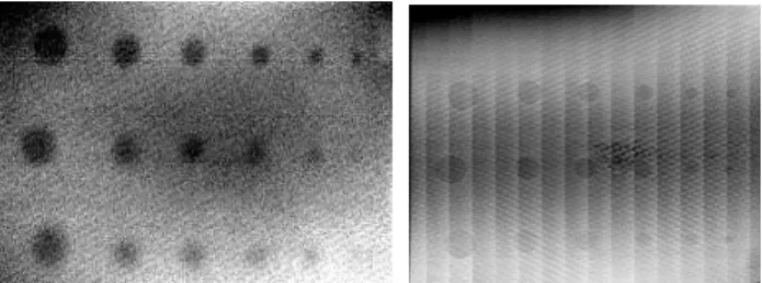
For aviation industry, the AITM standards are precisely based on the NDT ultrasonic testing for the validation of composite structures [1, 2, 3, 4]. However, such technique is very restrictive in terms of used transducers and inspected part shape (local measurement technique). Since recent years, the use of full-field measurement NDT as infrared (IR) thermography [5, 6, 7, 8, 11] and X-ray tomography [9, 10, 12] are developing for their fast execution and analysis (defect mapping in one shot) and for the global inspection aspect (full-field measurements (Figure 1)).
Figure 1: 2D defect map, IR thermography on the left and X-ray tomography on the right This work consists in characterizing and in comparing three full-field measurement NDT in order to define the defect detection limits, the advantages and the limitations for each technique on multi-layered and sandwich composite structures.
1. Different full-field measurement NDT
In this work, we use two different techniques of IR thermography with a 2D full-field measurement and the X-ray tomography with a 3D map.
1.1. IR thermographic NDT
These two IR thermographic methods differ in the nature of the heat sources.
1.1.1. IR thermography (IRT)
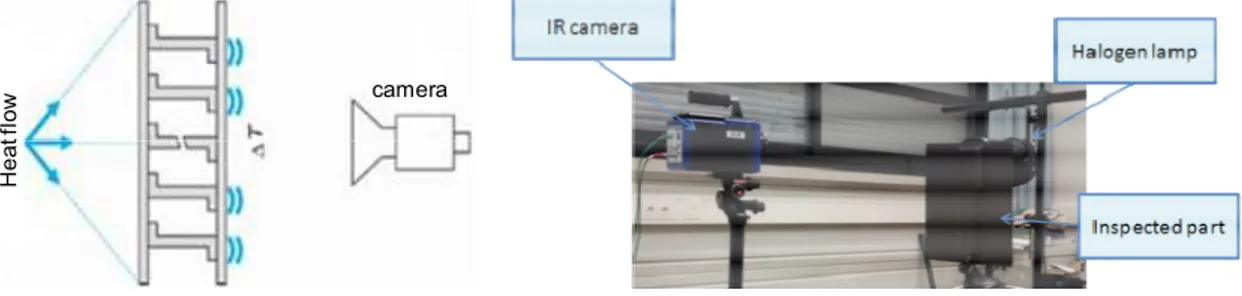
The principle of the IR thermography is to stimulate the surface of an inspected composite part with our infrared light source. The solicitation duration depends of the specimen thickness, the material and its emissivity by the halogen lamp [13]. The sample is stimulated by a heat flow whose distribution can be considered as square pulse stimulation. The full-filed measurement is carried out on the sample surface with a IR camera. The result is a 2D defect mapping in one shot as Figure 1. This technique is used on two experimental devices: the transmission and the reflection. The transmission consists in having the halogen lamp in the opposite side of the camera (figure 2) whereas for the reflection, the halogen lamp and the camera are on the same side (figure 3).
camera H e a t f lo w
Figure 2: Transmission setup of IR thermography
camera H e a t f lo w
Figure 3: Reflection setup of IR thermography
During the test procedure, the specimen is heated by the thermal stimulation and its response is continuously recorded. The analysis of temperature map enables to identify defects within the composite materials.
In our study, the following equipments have been used: • 2 halogen lamps 230V 1000W,
• a signal amplifier (supplier: PULSAR),
• an infrared camera JADE retrofited in Titanium, 20 mK resolution, lens: MW 50 mm 2.0 Jade (supplier: FLIR),
1.1.2. Pulse IR thermography (PIRT)
The Pulse IR thermography has a closed setup to IR thermography, only the type of excitation is changing. A pulse excitation is sending to the inspected surface of the sample. The main advantage of this heating configuration is to stimulate all the frequencies of the material during a very short time. The evolution of the surface temperature is recorded by a camera (around 500 images) and a specific signal treatment, developed by Thermicar and I2M-TREFLE department, is applied to obtain a physical 2D defect mapping relating to the thermal properties of the material.
To combine a full field detector (IR camera) with a pulse heat excitation allows a quick control of large composites. For example, a multi-layered composite plate of 2 mm thickness can be controlled in 2 seconds.
In our study, the following equipments have been used (figure 4): • 2 flash lamps 230V 1500J,
• an infrared camera SC7500, 20 mK resolution (supplier: FLIR), • ALTAIR software,
• THERMO-CND software (supplier: THERMOCONCEPT).
Figure 4 : THERMOCONCEPT experimental device
1.2. X-ray tomographic NDT
Principle of X-ray tomography acquisition is based on the emission and reception of X-rays through a material. In function of the specific density of analyzed materials, there are differences in the X-rays absorption, and so a diminution of initial X-X-rays intensity. This physical phenomenon is described for homogeneous materials by the Beer-Lambert law.
Images acquisition is realized by step of rotation of specimen, mounted on the tomograph plate, between X-ray source and sensor. Complete analysis considers a full rotation of 360° of the specimen around the X-rays source. The X-ray tomography is illustrated in Figure 5. Results are a series of images corresponding to each slices of the specimen. Images are computed to make a tomographic reconstruction of the volume, which is analyzed for control applications or used to calculate physical fields in the specimen thickness [14].
Figure 5 : Tomographic images acquisition principle
There is also another kind of X-ray tomograph equipment, which is directly a deviation of medical X-ray scanner. This equipment enables to carry out measurement on bigger parts, but the resolution is less interesting than the industrial tomograph. Figure 6 presents a Siemens 140 keV medical tomograph used for industrial applications by the TomoAdour society (Pau, France). It enables to make studies on 2000 x 500 x 500 size part (human scale) [14].
Figure 6 : Medical X-ray scanner used for composite part tomographic investigation
X-ray tomography technique has been used to evaluate the potential in the composite defect study. This technique is a way to analyse an internal damage of materials. Indeed, by an X-ray beam through a sample in a high number of positions, a 2D reconstruction showing the section of a slice (0.3 mm thick) was performed for all measured positions (Figure 5). The image sequence thus obtained represents the different sections reconstructed over the total sample. These grayscale images reflect the differences in X-ray attenuation by the internal structure of the sample measured in function of difference of density. Any defect or damaged zone is directly visualized on tomographic sections through the density contrast [14].
2. Results
These three full-field measurement NDT are applied on the four following composite samples (Figure 7):
1. A multi-layered composite with flat-bottomed holes defects, 2. A multi-layered composite with Teflon insert defects,
3. A foam-core composite with Teflon insert defects (skin thickness = 1.08 mm), 4. A foam-core composite with Teflon insert defects (skin thickness = 0.66 mm).
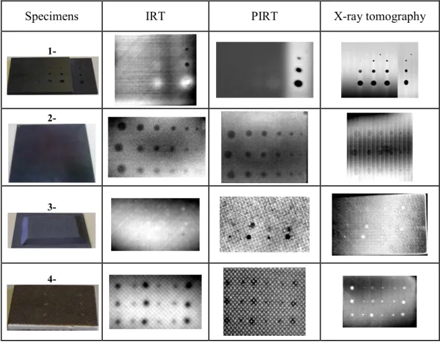
Figure 7: The four multi-layered and sandwich composite specimens
This work intends, in a qualitative and a quantitative analyze, to characterize and to compare two different IR thermographic techniques and the X-ray tomography on two laminates (carbon-epoxy) and two sandwichs (carbon-glass-epoxy and carbon-epoxy with foam-core) composite specimens (Figure 7). Artificial defects (flat-bottomed holes simulating porosities or Teflon inserts simulating delamination) as small flat discs with different diameters (from 15 mm to 2 mm diameter) have been realized and inserted at various depths of each specimen in order to identify the detection limit of these three techniques.
The results are presented according to two points of view: • a qualitative analyze for each sample,
• a quantitative analyze for each kind of structure.
2.1. Qualitative results
Table 1. Comparison between the three different full-field measurement NDT results
Specimens IRT PIRT X-ray tomography
1-
2-
3-
4-In Table 1, the results of specimen 1 (sample thickness from 4 mm to 8 mm depth) show that the specimen thickness is an important parameter for the detection by infrared thermography but not for X-ray tomography. Over 4 mm thick, IR thermography and pulse IR thermography hardly work, we detect only two defects. Concerning the 4 mm thick part, both IR thermographic methods are
powerful because they detect three defects. Only the 2 mm diameter defect is not identified. This defect size is the detection limit of both IR thermographic techniques. On this specimen, the most accurate and the most powerful method is the X-ray tomography which detects all the defects expected to one defect about 2 mm diameter.
For specimen 2 (2.8 mm thick), results are similar between the three techniques. On multi-layered composite of 2 mm or 3 mm thick (aviation industry composite), we use through transmission infrared thermography setting which gives results similar to those of X-ray tomography. Moreover, we note, for this sample, that the defect identification on the two IR thermographic mapping is easier than on the X-ray tomographic mapping because of the best contrast. Therefore, for this specimen, the qualitative results about both IR thermographic techniques are better than those of X-ray tomography.
Concerning foam-core composite (samples 3 and 4), X-ray tomography is more adapted than IR thermography because foam-core is a thermal insulation. Therefore, the foam-core can not be inspected by the transmission IR thermography. In order to control the two specimen skins we have to work in reflection setup which is an experiment setting with high noise measurement. By this experimental device, each skin is inspected in one shot. The different defects are more difficult to evaluate because of the large part of the noise measurement. In order to improve the result evaluation, we have to make image processing which can delete the heat spot. Nevertheless we lose also some important information as small defect. For these kinds of sample, between the two IR thermography techniques, the most accurate and the efficient is the pulse IR thermography because the used thermal source generates less noise measurement than halogen lamp.
2.2. Quantitative results
2.2.1. Multi-layered composite structures
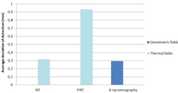
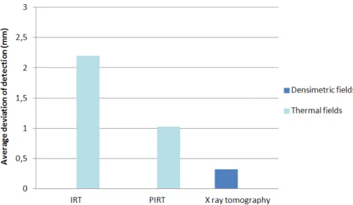
Figure 8: Quantitative results of multi-layered structures
The figure 8 shows the average deviation on the whole multi-layered structure detected defects (samples 1 and 2). In terms of detection accuracy, the performances of the X-ray tomography and the IRT are quite similar whereas the PIRT are much less accurate. This is explained by the large thickness of the specimen 1 related to the quick stimulation used by the PIRT. Moreover, we can not measure the two identified defects on the thicker part of the specimen 1 because of the very low contrast on the PIRT mapping.
Table 2. Percentage of detected defects on multi-layered structures
The observed difference, in terms of accuracy performance for the thermal full-field measurements, is lower on the percentage of detected defects (Table 2). Thus, the PIRT is more efficient in terms of detection than in terms of detection accuracy. The X-ray tomography is always the best.
2.2.2. Foam-core composites structures
Figure 9: Quantitative results of foam-core structures
The graph on figure 9 shows that the most accurate technique on foam-core structure is the X-ray tomography. Both IR thermographic NDT are not very precise because the reflection setup used on foam-core composite part is the noisiest experimental device. Thus, the cartography contrast is very low and the defect sizing is very difficult to determine.
Table 3. Percentage of detected defects on foam-core structures
As figure 9, the table 3 demonstrates that the X-ray tomography on foam-core composite structures is the most efficient technique. Moreover, thanks to it quick stimulation, the PIRT is the least noisy of both the two thermal full-field measurement methods. Therefore, it is the most accurate and efficient thermal method. However, in terms of efficiency, their quantitative results are similar because the mapping contrast is sufficient to identify defects but not to size correctly.
Contrary to the multi-layered structures results, the efficiency of these three full-field measurement NDT are very similar on the foam-core structures (table 3).
Conclusion
X-ray tomography is the more adapted NDT at macroscopic scale because it is the only one which can hardly detect all defects in any composite parts. Moreover, in comparison with other studies about defect detection limits [15, 13], the X-ray tomography is the more precisely NDT. Its great advantages are the 3D full-field measurement and the capacity to inspect foam-core structure in sandwich composite. These limitations are its expensive price, its limited volume of inspected parts and its particular experiment conditions.
Both techniques about IR thermography presented in this work give similar results to X-ray tomography concerning aviation industry monolithic composite part (2 mm or 3 mm thick) and some kinds of sandwich composite part. These methods detect often the totality of sample defects and their accuracy is near of X-ray tomography and ultrasound accuracy [13]. Furthermore, these advantages are its cheaper price, its fast execution and analysis (2D mapping in one shot for little structure), its full-field measurement (global inspection), its portability and its no-limited volume of inspected parts. Its limitation in comparison with X-ray tomography is the 2D measurement and the impossibility to control foam-core structure in sandwich composite.
References
[1] AITM6-0013: Evaluation of conventional ultrasonic inspection facilities, equipment and probes, 2008
[2] AITM6-4002: Ultrasonic through transmission – inspection of fibre composite, 2008. [3] AITM6-4010: Inspection of fibre composites by ultrasonic phased array technique, 2008. [4] AITM6-4005: Ultrasonic pulse-echo inspection of carbon fibre plastics, 2010.
[5] P. Bremond, Lock-in thermography: a tool to mesure stress and to detect defects in aircraft industry, in AIAC, Canberra Australia, 2001
[6] A. Chrysochoos, 2002. La thermographie infrarouge un outil en puissance pour étudier le comportement des matériaux, Mécanique & Industries, 3, 3–14.
[7] Guibert, S. 2007. La thermographie infrarouge à détection synchrone appliquée aux matériaux composites, Master’s thesis, Université de LAVAL, QUEBEC
[8] Lambert, A., J. Rivenez, G. Waché, and M. Cherfaoui. 1994. Les contrôles non destructifs généralités, Tech. rep., Cahiers Formation CETIM
[9] Babout, L. 2002. Etude par tomographie X et modélisation de l’endommagement de matériaux métalliques modèles, Ph.D. thesis, Institut National des Sciences Appliquées de Lyon
[10] Badel, P. 2008. Analyse mésoscopique du comportement mécanique des renforts tissés de composites utilisant la tomographie aux rayons X, Ph.D. thesis, Institut National des Sciences Appliquées de Lyon.
[11] C. Meola, G. M. Carlomagno, A. Squillace, A. Vitiello, Non-destructive evaluation of aerospace materials with lock-in thermography, Engineering Failure Analysis, 13 p. 380–388 (2006).
[12] V. Carmona, Etude de l'endommagement de matériaux composites par tomographie X et émission acoustique, Thèse de l'Institut National des Sciences Appliquées de Lyon, (2009). [13] E. Péronnet, F. Eyma, M-L Pastor, H. Welemane, Caractérisation et comparaison des limites de
détection de techniques de contrôle non destructif : méthodes ultrasonores et méthodes optiques, Conférence CMOI Toulouse (2010).
[14] E. Péronnet, S. Mistou, R. Brault, C. Garnier, M. Fazzini, X-Ray tomography for composite parts design, Conférence FVR2011 Poitiers (2011).
[15] E. Péronnet, F. Eyma, H. Welemane, C. Pescay, Characterization and comparison of defects detection limits of three ultrasonic non destructive methods, Conférence ICEM14 Poitiers (2010).