Publisher’s version / Version de l'éditeur:
Journal of Loss Prevention in the Process Industries, 19, November 6, pp. 516-526, 2006-11-01
READ THESE TERMS AND CONDITIONS CAREFULLY BEFORE USING THIS WEBSITE.
https://nrc-publications.canada.ca/eng/copyright
Vous avez des questions? Nous pouvons vous aider. Pour communiquer directement avec un auteur, consultez la
première page de la revue dans laquelle son article a été publié afin de trouver ses coordonnées. Si vous n’arrivez pas à les repérer, communiquez avec nous à PublicationsArchive-ArchivesPublications@nrc-cnrc.gc.ca.
Questions? Contact the NRC Publications Archive team at
PublicationsArchive-ArchivesPublications@nrc-cnrc.gc.ca. If you wish to email the authors directly, please see the first page of the publication for their contact information.
NRC Publications Archive
Archives des publications du CNRC
This publication could be one of several versions: author’s original, accepted manuscript or the publisher’s version. / La version de cette publication peut être l’une des suivantes : la version prépublication de l’auteur, la version acceptée du manuscrit ou la version de l’éditeur.
For the publisher’s version, please access the DOI link below./ Pour consulter la version de l’éditeur, utilisez le lien DOI ci-dessous.
https://doi.org/10.1016/j.jlp.2005.12.009
Access and use of this website and the material on it are subject to the Terms and Conditions set forth at
Characteristics of large cooking oil pool fires and their extinguishment by water mist
Liu, Z. G.; Carpenter, D. W.; Kim, A. K.
https://publications-cnrc.canada.ca/fra/droits
L’accès à ce site Web et l’utilisation de son contenu sont assujettis aux conditions présentées dans le site LISEZ CES CONDITIONS ATTENTIVEMENT AVANT D’UTILISER CE SITE WEB.
NRC Publications Record / Notice d'Archives des publications de CNRC:
https://nrc-publications.canada.ca/eng/view/object/?id=81c8bf58-4670-4651-8b4c-8958be784f22 https://publications-cnrc.canada.ca/fra/voir/objet/?id=81c8bf58-4670-4651-8b4c-8958be784f22
http://irc.nrc-cnrc.gc.ca
Cha ra c t e rist ic s of la rge c ook ing oil pool
fire s a nd t he ir ex t inguishm e nt by w at e r
m ist
L i u , Z . ; C a r p e n t e r , D . ; K i m , A . K .
N R C C - 4 8 1 3 9
A version of this document is published in / Une version de ce
document se trouve dans: Journal of Loss Prevention in the
Process Industries, v. 19, no. 6, Nov. 2006, pp. 516-526 doi:
CHARACTERISTICS OF LARGE COOKING OIL POOL FIRES AND THEIR EXTINGUISHMENT BY WATER MIST
Z. Liu1, D. Carpenter and A. K. Kim
Fire Research Program, Institute for Research in Construction National Research Council of Canada, Ottawa, Canada, K1A 0R6,
ABSTRACT
Large cooking oil pool fires, occurring in industrial oil cookers, present a severe hazard to food processing plants due to their size and the large amount of hot oil involved. This paper reports a series of full-scale fire experiments conducted in a large industrial oil cooker mock-up. The characteristics of large cooking oil pool fires and the effect of oil depth and hood position in the oil cooker on fire growth were studied. The use of water mist for extinguishing large oil pool fires and their extinguishing performance under different discharge pressure and with different types of water mist systems were investigated. Experimental results showed that the cooking oil underwent a substantial expansion in volume during heating. The fires developed quickly once the oil auto-ignited. The fire growth rate was affected by the oil depth in the pan and the hood position in the oil cooker. The water mist fire suppression systems effectively extinguished large cooking oil fires and prevented them from re-igniting. Their extinguishing performance was determined by the type of water mist system, discharge pressure and hood position in the oil cooker.
Key Words:water mist, fire extinguishment, cooking oil fire, industrial oil cooker
INTRODUCTION
Large industrial oil cookers are used in many major food processing plants. They contain a large quantity of oil and also have a large surface area of up to several hundred square feet (FM Global, 2003, Nam, 2002). A very severe fire could occur in the industrial oil cooker by overheated oil reaching its auto-ignition temperature due to a system malfunction or simple human error. These fires are very challenging and present a severe hazard to the food processing plant as the fire spreads rapidly over the oil surface and forms a large fire involving a large oil surface and tons of hot oil up to 18,900 liters. To extinguish the fire, it requires flame extinction over the entire surface at once, and at the same time, rapid cooling of the oil to prevent it from re-igniting.
Currently, there is limited information on the characteristics of large cooking oil pool fires and the option of using appropriate fire suppressants to extinguish such large fires is also limited. For example, fire suppressants that contain chemical components are not allowed to be used in the food processing industry due to considerations of food safety. Sprinkler water sprays, as shown in the previous research (Nam, 2002), were able to extinguish industrial oil cooker fires, but extensive oil was spilled over the oil cooker
1
and formed large fires on the ground, as coarse water droplets sank and boiled up in the hot oil. Carbon dioxide is commonly used for industrial oil cooker protection. It is capable of extinguishing flames over the oil surface, but it cannot effectively prevent re-ignition, because carbon dioxide does not have a sufficient cooling capacity to cool the oil below its auto-ignition temperature, especially for the vegetable oils that have high burning temperatures.
Water mist that consists of small water droplets (Dv99 < 1000 microns) has been
used to successfully extinguish various types of fires (Back, 1994, Liu & Kim, 2000, Mawhinney, 1997, Liu & Kim, 2001, Mawhinney, 2002) including cooking oil fires occurring in a commercial deep fat fryer (Liu, Kim, Carpenter, Kanabus-Kaminska & Yen, 2004). They have demonstrated good fire extinguishing and oil cooling capabilities in these applications. However, the feasibility of using fine water mist against large pool fires associated with the industrial oil cookers has not previously been investigated.
The National Research Council of Canada (NRC), with CAFS Unit Inc., carried out a research program to study large pool fires associated with industrial oil cookers and their extinguishment by water mist fire suppression technology. A testing facility with large industrial oil cooker mock-ups was built. Two water mist fire suppression systems were developed and evaluated in the program. Research results on water mist extinguishing mechanisms and criteria required for extinguishing large cooking oil pool fires have been reported (Liu, Carpenter & Kim, 2005). This paper will provide detailed descriptions of the characteristics of large pool cooking oil fires under various operating conditions, and the spray and fire extinguishing performance of two water mist systems developed in the research program. The impacts of the types of water mist systems and their configurations, discharge pressure, oil quantity in the cooker, and hood position on the effectiveness of the water mist systems for suppressing large cooking oil fires will also be reported.
INDUSTRIAL OIL COOKER MOCK-UP
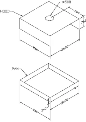
An industrial oil cooker mock-up was built in the project. It consisted of a pan and a hood (see Figure 1). The pan was 3.0 m long, 2.4 m wide and 0.343 m deep. The dimension of the hood was 3.05 m long, 2.6 m wide, and 0.76 m deep. Both ends of the hood were open. There was a 0.51 m diameter hole on top of the hood at the center to simulate the connection with the exhaust duct. The distance from the center of the hole to either end of the hood was 1.5 m. A burner was centered beneath the pan in which the heat was distributed relatively uniformly throughout the pan surface. Propane gas was used as the heating source.
During the experiments, the hood was placed manually in one of two different positions: namely a hood-up or a hood-down position. The clearance between the hood and the pan was 0.46 m at the hood-up position and 0.05 m at the hood-down position.
Figure 1. Schematic of industrial oil cooker mock-up (dimensions in the figure are in mm)
INSTRUMENTATION
A number of instruments were used in the experiments to monitor the fire growth, water mist discharge and fire suppression process. These included thermocouples, pressure gauges, heat flux meters, oxygen
analyzers, water flow meters and video cameras.
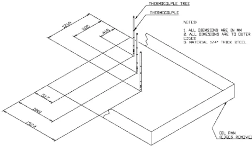
Three thermocouple trees were placed in the pan to measure oil temperatures and air/flame temperatures above the oil surface, as shown in Figure 2. Thermocouple tree #1 was placed in the center of the pan and thermocouple trees #2 and #3 were located 0.7 m apart from each other along the direction from the center of the pan to the southeast corner of the pan. Eight thermocouples (Type K, 18 gauge) were attached to each tree. The elevation of each thermocouple was 51 mm, 100 mm, 124 mm, 165 mm, 254 mm, 381 mm, 681 mm and 981 mm, respectively, above the bottom of the pan, while the oil depth was 127 mm. The elevations of the thermocouples were changed to 25 mm, 40 mm, 60, mm, 80 mm, 254 mm, 381 mm, 681 mm and 981 mm, when the oil depth was reduced to 51 mm.
Two pressure gauges (Omega PX300) were used to monitor the discharge pressure of the water mist system. The first one was located in the inlet of the water mist piping system and another was located near one of the nozzles. The real discharge pressure was determined based on the data measured near the nozzle.
Two heat flux meters (air-cooled, Medtherm Corporation Gardon Gage) were placed at the north and south sides of the cooker to measure the heat release rate of the fire and any possible fire flare-up generated in suppression. The distance from the heat flux meter to the cooker was 1.0 m and the height of the meter was 1.1 m above the floor.
Three video cameras were used in the experiments to record the testing process. One was located at the southeast side of the cooker, the second one at the west side of the cooker, and the third one was an aerial-view camera and elevated 7 m above the ground at the east side of the cooker.
Figure 2. Schematic of thermocouple tress in the oil pan
One flow meter (Krohne IFC 010 D) located in the inlet of the water mist system was used to measure the water flow rate of the water mist system.
PROCEDURE
Canola oil was used as the cooking oil in the experiments. The properties of the canola oil are listed in Table 1.
Table 1. Physical Property of Canola Oil (Nam, 2002, Przybylski, 1999)
Oil Flash Point
(K) Auto-ignition temperature (K) Density (kg/L) Specific heat (kJ/kg.K) Heat release rate (MW/m2) Canola 505-563 603-633 0.914 1.91 1.81
Two oil depths of 5.1 cm and 12.5 cm were used in the tests. Fresh cooking oil was introduced into the pan and then heated continuously at 3-5oC/min until it auto-ignited. After the flame had spread over the entire oil surface, the fire was allowed to burn freely for 30 sec, which ensured that people in a real fire had sufficient time to evacuate from the industrial oil cooker area before the activation of a suppression system, according to the Test Protocol (FM Global, 2003). Heating was provided continuously during the pre-burning period until the start of the water mist discharge.
At the end of the pre-burning period, the water mist discharge was activated manually. After the fire was extinguished, the discharge of water mist was maintained for a period of time to cool the cooking oil and to prevent it from re-ignition. During the experiments, all test data, including temperature, pressure, heat flux and water flow rate, were collected by a data acquisition system in 1 s interval.
Figure 3. Schematic of spray measurement for a single nozzle
Figure 4. Schematic of spray measurement in oil pan for a water mist system
WATER MIST SYSTEMS AND THEIR SPRAY PERFORMANCE
Water flow rate, spray coverage and spray momentum are considered as the most important criteria required for water mist to extinguish a cooking oil fire (Liu, Kim, Carpenter, Kanabus-Kaminska & Yen, 2004). The critical water mist fluxes required for extinguishing the flame and cooling the oil for fire suppression were estimated as 8.6 and 2.8 kg/m2.min, respectively, based on canola oil properties, such as their heat of combustion, heat release rate and gasification, as well as the water cooling capacity (Liu, Kim, Carpenter, Kanabus-Kaminska & Yen, 2004). The water mist coverage required was that it must be large enough to cover the entire oil surface, which enabled the water mist to attack the flames over the whole oil surface and extinguish them at once. The requirement for the water mist momentum was that it must be sufficient enough to allow water droplets to penetrate the fire plume and reach the fuel surface. It suggests that the water spray momentum must be larger than the fire plume momentum that is mainly determined by the heat release rate of the fire.
According to the required water mist criteria, two water mist fire suppression systems with single fluid nozzles were developed and evaluated in the experiments. The spray performance of both single and group nozzles for the two water mist systems was studied.
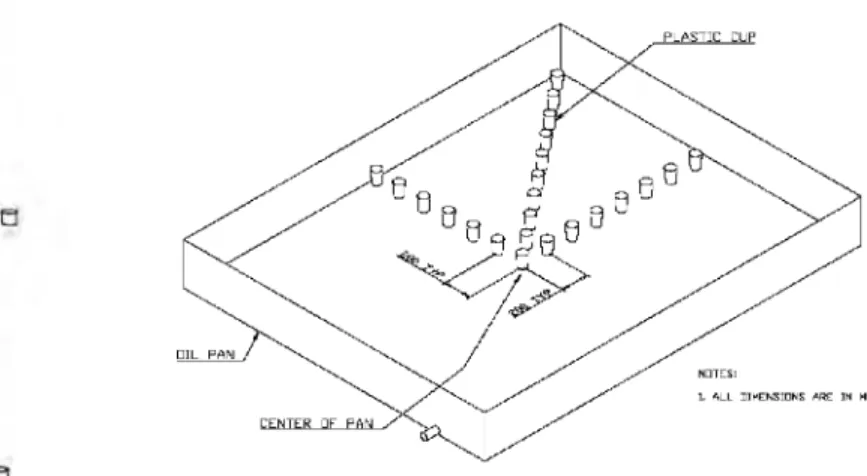
To measure the spray performance of a single nozzle, the nozzle was placed 1.0 m above the floor. More than 20 sampling cups with a 7.2 cm diameter were placed on the floor starting from the center of the spray coverage along the longitudinal, transverse and diagonal axis to measure the water density distribution and the size of the coverage area (see Figure 3). The distance between the cups was 20 cm. The amount of water collected by the cups was weighted after 1 – 3 minutes of discharge, depending on the
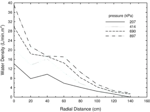
Figure 5. Water density distribution of a single nozzle of water mist system I
Radial Distance (cm) 0 20 40 60 80 100 120 140 160 W ate r D ensity (L/min.m 2) 0 4 8 12 16 20 24 28 32 36 40 207 414 690 897 pressure (kPa)
discharge pressure. The change in spray angle with discharge pressure was recorded and measured by a digital camera as well as a digital video camera.
To measure the spray performance of the water mist system in the oil cooker, 23 sampling cups were placed on the floor of the oil pan to measure the water density distribution in the pan. They were distributed from the center of the pan along the longitudinal, transverse and diagonal axis of the pan (see Figure 4). The distance between the cups was 20 cm. The amount of water collected in the cups was weighted after the water mist discharge. The total amount of water collected in the pan was determined by measuring the water depth in the pan after the cups were emptied into the pan. The water collection ratio in the pan was defined as the ratio of the total water collected in the pan to the total water discharged by the water mist system.
Water Mist System I
Water mist system I consisted of a number of MistShieldTM nozzles that are provided by CAFS Units, Inc. and a piping system. The water flow rate of a MistShieldTM nozzle ranges from 28.2 L/min at 414 kPa to 40.9 L/min at 862 kPa discharge pressure. The water drops generated are relatively fine. Under a pressure of 552 kPa (80 psi), 50 and 90 percentages of the spray volume in drops are smaller than 250 and 380 microns, respectively. The spray angle of the nozzle was 150 degrees and did not change with an increase in discharge pressure.
The spray coverage area generated by a MistShieldTM nozzle was approximately 2.8 m diameter at 1.0 m below the nozzle
(see Figure 5). The water density distributed in the coverage area was not uniform, but decreased with the distance from the spray center. At 414 kPa discharge pressure, water density decreased from 20 L/min.m2 at the center of the spray cone to 1.2 L/min.m2 at 1.4 m away from the center of the spray cone. When the discharge pressure was increased, the water density at the center of the spray cone was substantially increased, while the water density near the edge of the spray cone had a minor increase. The spray coverage did not change with a change in discharge pressure.
To extinguish a cooking oil fire in the oil cooker mock-up used in the research program, water mist system I consisted of four MistShieldTM nozzles, and these were installed inside the cooker mock-up and placed 0.93 m above the bottom of the pan. The spacing of the nozzles was 1.22m x 1.52 m. The distance from the nozzles to the side walls of the pan was 0.6 m and to ends of the pan was 0.75 m. The configuration of water mist system I in the oil pan is shown in Figure 6.
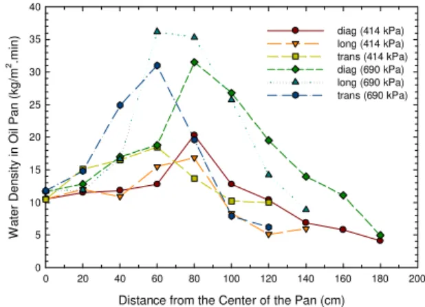
Figure 7. Water density distribution of water mist system I in the oil pan under two discharge pressures Figure 6. Plan view of the configuration of water
mist systemI
Distance from the Center of the Pan (cm)
0 20 40 60 80 100 120 140 160 180 200
W
ater Density in Oil Pan (kg/m
2.min) 0 5 10 15 20 25 30 35 40 diag (414 kPa) long (414 kPa) trans (414 kPa) diag (690 kPa) long (690 kPa) trans (690 kPa)
Water mist generated by system I was able to cover the whole oil pan surface. Figure 7 shows the water density distribution over the pan under 552 kPa discharge pressure (x-axis is the distance from the center of the pan). It was different from that generated by a single nozzle due to the overlap of water mist. Higher water density was distributed underneath the nozzles and the areas between the nozzles where the water spray overlaps. The water density at the corner of the pan was the lowest (5.2 L/m2.min at 552 kPa), while the water density at the center of the pan (12.1 L/m2.min at 552 kPa) was two times higher than that at the corner of the pan.
Under 414 kPa discharge pressure, the total water flow rate of water mist system I was 112.8 L/min and approximately 84.2% of discharged water was collected by the pan. The average water density in the pan was 13.2 L/m2.min. With an increase in discharge pressure, the water delivery densities in the pan increased but its spray coverage pattern and water collection ratio did not change because there was no change in its spray angle, as shown in Figure 7.
Water Mist System II
Water mist system II consisted of a number of swirl type nozzles and a piping system. The water droplets generated by water mist system II are relatively coarser, compared to water mist system I. Under a pressure of 552 kPa (80 psi), 50 and 90 percentages of the spray volume in drops are smaller than 300 and 540 microns, respectively. Its water flow rate varies from 19.1 L/min at 414 kPa to 24.3 L/min at 862 kPa discharge pressure. Its spray angle is substantially decreased with an increase in discharge pressure. Its 120 degrees of the spray angle at 207 kPa of the discharge pressure decreases to 80 degrees as the discharge pressure increases to 896 kPa.
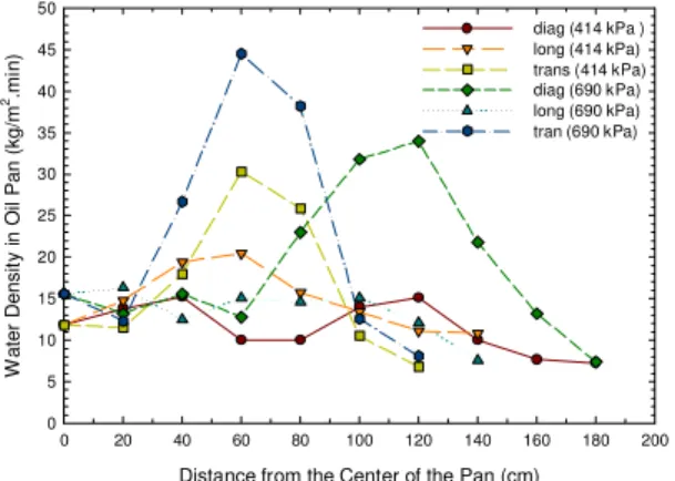
Figure 10. Water density distribution of water mist system II in the oil pan
Figure 8. Water density distribution of a single nozzle of water mist system II
Figure 9. Plan view of the configuration of water mist system II
Radial Distance (cm)
0 20 40 60 80 100 120
W
ater Density (L/min.m
2) 0 5 10 15 20 25 30 35 40 45 50 55 60 65 70 207 414 690 897 pressure (kPa)
Distance from the Center of the Pan (cm)
0 20 40 60 80 100 120 140 160 180 200 W ater Densit y i n Oil Pan (kg/m 2.mi n) 0 5 10 15 20 25 30 35 40 45 50 diag (414 kPa ) long (414 kPa) trans (414 kPa) diag (690 kPa) long (690 kPa) tran (690 kPa)
The spray coverage of a single nozzle of water mist system II is reduced with an increase in discharge pressure. As shown
in Figure 8, the radius of the coverage area at 206 kPa discharge pressure is approximately 1.2 m at 1.0 m below the nozzle. However, with an increase in discharge pressure to 896 kPa, the coverage area was reduced to an area with a 0.8 m radius and water density at the center of the coverage increased significantly.
To cover the entire oil surface, six nozzles of water mist system II were installed inside the mock-up and placed 1.03 m above the bottom of the pan. The spacing of the nozzles was 1.22 m x 1.00
m. The distance from the nozzles to the side walls of the pan was 0.6 m and to the ends of the pan was 0.5 m. The configuration of water mist system II in the oil pan is shown in Figure 9.
The water collection ratio in the pan produced by water mist system II was lower than that with water mist system I. Under 414 kPa discharge pressure, the total water flow rate of water mist system II was 114 L/min and its water collection rate in the pan was 80.4%. Its average water density in the pan was 12.7 L/min.m2. With increasing discharge pressure, the water collection ratio and the average water density in the pan were increased.
Figure 10 shows the water density distribution of water mist system II over the oil pan. Its water spray was also able to cover the whole oil pan, however, its spray pattern
was different from that observed in water mist system I. High water density appears underneath the nozzle, and the water density near the edge of the pan was higher than that with water mist system I, but the water density in the center area of the pan along the longitudinal direction was lower than that with water mist system I. The water distribution pattern was also changed with the change in discharge pressure. As shown in Figure 10, with an increase in the discharge pressure, the water delivery density along the longitudinal direction was reduced and tended to be uniform, while the peak water delivery density along the diagonal direction was shifted towards the edge of the pan. These changes were caused by a reduction in the spray angle with increasing discharge pressure.
FIRE EXPERIMENTS
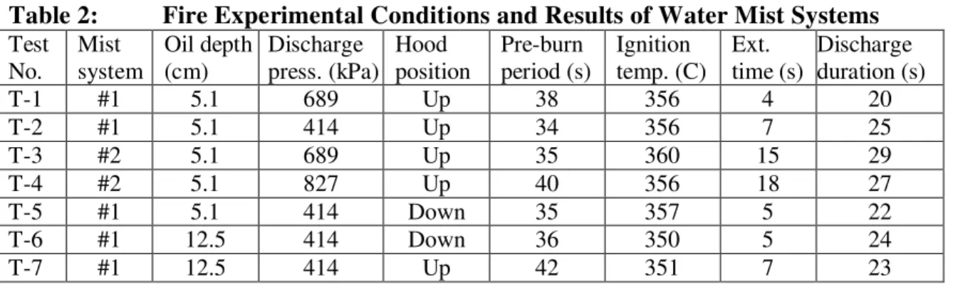
Seven full-scale fire experiments were conducted. The characteristics of large cooking oil pool fires under various operating conditions and their extinguishment by water mist were examined. The effects of hood position, discharge pressure, and the type of water mist system on fire suppression performance were investigated. During the fire experiments, the discharge pressure employed was 414 kPa and 689 kPa, respectively, for water mist system I, and 689 kPa and 827 kPa, respectively, for water mist system II. The vertical distance between the nozzle tip and the bottom of the pan was maintained around 0.93 m for water mist system I and 1.03 m for water mist system II, when the oil depth in the pan was 12.5 cm at room temperature. Testing conditions and results are listed in Table 2 in which the pre-burning period is defined as the time interval between the ignition of the fire and the activation of the water mist system. The extinguishing time is defined as the time interval between the activation of the mist system and the complete flame extinguishment in the oil cooker.
Table 2: Fire Experimental Conditions and Results of Water Mist Systems
Test No. Mist system Oil depth (cm) Discharge press. (kPa) Hood position Pre-burn period (s) Ignition temp. (C) Ext. time (s) Discharge duration (s) T-1 #1 5.1 689 Up 38 356 4 20 T-2 #1 5.1 414 Up 34 356 7 25 T-3 #2 5.1 689 Up 35 360 15 29 T-4 #2 5.1 827 Up 40 356 18 27 T-5 #1 5.1 414 Down 35 357 5 22 T-6 #1 12.5 414 Down 36 350 5 24 T-7 #1 12.5 414 Up 42 351 7 23
Characteristics of Cooking Oil Fires:
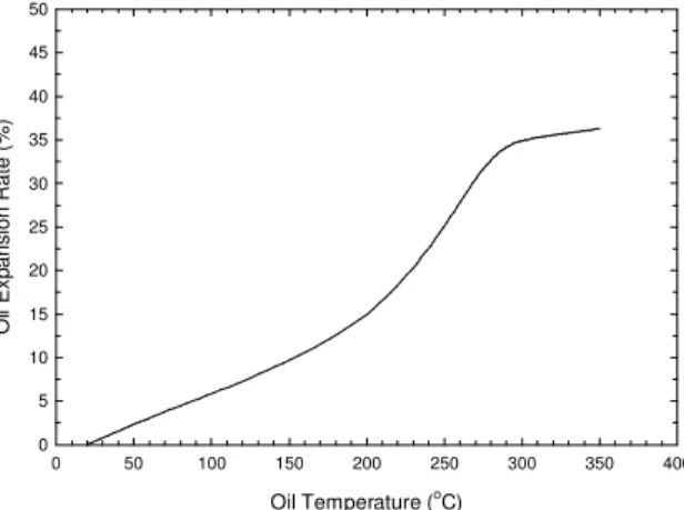
Fresh canola oil was introduced in the pan and heated continuously until it auto-ignited. The oil underwent a significant expansion in volume during heating and the oil depth in the pan was raised with an increase in the oil temperature. Figure 11 shows the variation of the oil expansion rate with the oil temperature. It indicates that the oil expands quickly to approximately 35% more than its original volume in the temperature range from 200oC to 280oC and then the oil expansion is slowed down. In addition, using the same heat power input, the rate of increase of the oil temperature was slowed down as
Figure 11. Variations of oil expansion rate with oil temperature
Figure 12. Smoke and oil vapour generated over the oil surface during heating
Oil Temperature (oC) 0 50 100 150 200 250 300 350 400 Oi l Exp ansion Rate (%) 0 5 10 15 20 25 30 35 40 45 50
the oil became hot. This is because the specific heat or heat capacity of the oil increased with the oil temperature. The specific heat of canola oil at room temperature is 1.91 kJ/kg.K but its average value at the temperature range of 20oC to 160oC increases to 2.5 kJ/kg.K (Nam, 2002).
After the oil was heated to 220oC, the smoke/oil vapour appeared over the oil surface and became very dense with the increase in oil temperature. They filled the inside of the oil cooker as the oil temperature was near the auto-ignition point, as shown in Figure 12. It was an indication of impending oil auto-ignition in the cooker. During the seven experiments, the oil auto-ignited at temperatures ranging from 351oC to 361oC. The flame consumed all the fuel vapour over the oil surface that was generated in the heating period and quickly spread to the whole oil surface once the oil auto-ignited.
During the free burning, the fire fully developed, filling inside the cooker and reaching outside the oil cooker (see Figure 13). A large amount of dark smoke was also produced with the fire growth. The fire size generated in the fire experiments was approximately 13.03 MW, based on canola oil’s properties and the size of the oil pan used in the experiments.
Figure 14 shows the variation of gas temperatures measured at the center of the oil pan along the vertical distance above the oil surface at two different pre-burning times in test T-1. The gas temperature above the oil surface quickly decreased with the increase in the distance from the oil surface, when the pre-burning time was at 20 seconds, while after only 10 more seconds of pre-burning, the gas temperature above the oil surface shows a different trend. The gas temperature near the ceiling of the hood was higher than that close to the oil surface. It indicates that the fire developed very quickly and the flame reached the hood and spread under the ceiling of the hood.
The oil temperature was continuously increased during pre-heating. The fire with a shallow oil depth in the pan grew more quickly than the fire with a deep oil depth,
Figure 13. A cooking oil fire in pre-burning period Figure 14. Variation of gas temperatures along vertical distance above oil surface at two different pre-burning times
Figure 16. Variation of maximum gas temperatures with change in distance from center of oil pan during pre-burning Time (s) 1200 1220 1240 1260 1280 1300 1320 1340 Heat Flux (kW /m 2 ) 0 5 10 15 20 25 30 35 40 45 50 55 60 5.1 cm 12.7 cm Oil depth
Figure 15. Variation of the heat flux of the fires with two different oil depths
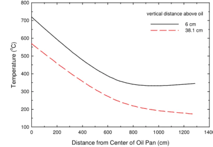
Distance from Center of Oil Pan (cm)
0 200 400 600 800 1000 1200 1400 T emperat ure ( o C) 100 200 300 400 500 600 700 800 6 cm 38.1 cm vertical distance above oil
Temperature (oC) 100 200 300 400 500 600 700 800 Ver tica l Distance above O il Pan (cm) 0 10 20 30 40 50 60 70 80 90 100 110 20 s 30 s oil surface nozzle location Pre-burning time
because the shallow oil was more quickly heated to a high temperature by the flame and the heating source and released more oil vapour that supported a large fire. Figure 15 compares the heat fluxes measured in the tests with two different oil depths in the oil pan. The heat flux with a 5.1 cm oil depth increased more quickly than that with a 12.7 cm oil depth and its maximum heat flux measured in the test was approximately 55 kW/m2, while the maximum heat flux in the test with 12.7 cm oil depth was only 11 kW/m2.
Figure 16 shows the variation of maximum gas temperatures at different vertical distances above the oil surface with a change in distance from the center of the oil pan during pre-burning. The flame temperatures measured at the center of the oil pan were higher than those measured at the other two locations of the cooker. They decreased with an increase in distance from the center of the oil pan. Distribution of the flame temperature suggested that the fire load in the oil pan was not distributed uniformly and a higher water flux was required to extinguish the flame at the center of the oil pan than at the edge of the oil pan.
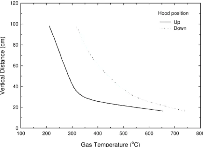
Figure 18. Fire extinguishment in an experiment Gas Temperature (oC) 100 200 300 400 500 600 700 800 Vertical Dist ance (cm) 0 20 40 60 80 100 120 Up Down Hood position
Figure 17. Maximum gas temperatures during pre-burning when hood was placed at two different locations
Experiments also showed that the hood position at the oil cooker had an impact on the fire growth. At the "hood-down" position, the fire grew more quickly than that at the “hood-up” position, because more heat was confined inside the cooker. As shown in Figure 17, maximum gas temperatures at the “hood-down” position were higher than those at the “hood-up” position, when they are at the same pre-burning time.
Fire Extinguishment
Both water mist systems developed in the project very effectively extinguished all the large cooking oil fires in the experiments. As observed in the experiments, with the discharge of water mist, the flame below the nozzle tip was extinguished quickly due to flame quenching and oxygen dilution by water mist, as the flame was hit directly by water mist and a large amount of steam was produced (see Figure 18). However, the flames near the ceiling of the hood that were not directly hit by water mist were not extinguished immediately and they accumulated near the ceiling of the hood and a part of them was pushed outside the cooker from the two ends of the hood. After a few more seconds of discharge, the entire flames were completely extinguished as the oil vapour generated from the oil was reduced due to oil cooling, and more steam was produced from the interaction between the water mist and the flame/hot oil. This acted to dilute the oxygen and fuel oil vapour available for the flame. The extinguishment of the flame located outside the water spray coverage area dictated the time required for extinguishing the fire in the industrial oil cooker.
The fire extinguishment process by water mist can be further explained from the variation of gas temperatures measured above the oil surface with time. As shown in Figure 19, in test T-7 with water mist system I, once the water mist discharge was activated, the temperatures below the nozzle tip quickly dropped as fine water drops cooled and extinguished the flame, while the temperature above the nozzle tip suddenly increased as some flames were pushed up. The gas temperature near the ceiling of the oil
Figure 19. Variation of gas temperatures above oil surface with time during fire suppression
Time (s) 1955 1960 1965 1970 1975 1980 1985 Temper ature ( oC) 100 200 300 400 500 600 700 16.5 cm 38.1 cm 98.1 cm Thermocouple location discharge extinguishing end of discharge
cooker was decreased more slowly than those at the lower portion of the oil cooker. After the fire was extinguished, the gas
temperatures far from the oil surface were cooled down to around 80oC and tended to be uniform. However, the gas temperature near the oil surface was still high at around 200oC, as the water mist hit hot oil and was converted into hot steam.
The extinguishment performance of water mist was dependent on the type of water mist system, discharge pressure, and hood position. However, as shown in the tests, the extinguishment performance of water mist system I was not affected by the oil depth in the pan, although the
fire size with a shallow oil depth was much larger than that with a deep oil depth.
The average water fluxes of the two water mist systems over the oil pan were similar and were higher than the critical one required to extinguish the canola oil fire when their discharge pressure was 414 kPa. However, water mist system I was more effective in extinguishing a cooking oil fire than water mist system II due to its large spray angle and relatively uniform water density distribution over the oil surface. Under a discharge pressure of 689 kPa, water mist system I extinguished the oil fire in 4 s, while it took 15 s for water mist system II to extinguish the same size of oil fire.
An increase in the discharge pressure resulted in an increase in the water flow rate and spray momentum. However, it did not mean that the performance of the water mist system would be improved with an increase in discharge pressure. For water mist system I, an increase in discharge pressure from 414 kPa to 690 kPa reduced extinguishing time from 7 s to 4 s. However, for water mist system II, an increase in discharge pressure from 689 kPa to 827 kPa resulted in an increase in extinguishing time from 15 s to 18 s. This is because an increase in the discharge pressure did not change the water spray angle of water mist system I and its spray distribution pattern, but reduced the spray angle of water mist system II, resulting in the reduction in the spray coverage area and changes in water density distribution. Local water densities of water mist system II at the center of the oil pan were reduced with an increase in discharge pressure, as observed in the spray experiments. During fire suppression with water mist system II, the flame was pushed out from the two ends of the hood under a low discharge pressure, while under a higher discharge pressure, the flame was pushed out, not only from the two ends of the hood, but also from two sides of the cooker due to the reduction in spray coverage.
The effect of changes in the discharge pressure on the performance of two water mist systems can be further confirmed from the variation of gas temperatures measured at
Figure 20. Variation of gas temperatures along vertical distance (5 s after discharge, system I)
Figure 21. Variation of gas temperatures along vertical distance (5 s after discharge, system II)
Gas Temperature (oC) 100 120 140 160 180 200 220 240 260 280 300 320 340 360 380 400 Ver tical Dista nce ab ove Bot tom of Oil Pan (cm) 0 20 40 60 80 100 120 690 kPa 828 kPa Discharge Pressure Gas Temperature (oC) 100 120 140 160 180 200 220 240 260 280 300 320 340 Ver
tical Distance abov
e Bottom of Oil Pan ( cm) 0 20 40 60 80 100 120 690 kPa 414 kPa Discharge pressure
the center of the pan. As shown in Figures 20 and 21, an increase in discharge pressure for water mist system I resulted in a decrease in gas temperatures under the tip of the nozzle, but led to an increase in the gas temperatures involving water mist system II. They suggested that an increase in discharge pressure had an opposite influence on the fire extinguishment of the two water mist systems.
Hood position in the oil cooker also had an impact on the extinguishing performance of water mist. For water mist system I under a discharge pressure of 414kPa, the extinguishing time was reduced from 7 s to 5 s, when the hood was placed from the ‘up’ position to the ‘down’ position. This is because the clearance between the nozzle tip and the hood ceiling was reduced with the hood in the “down” position, resulting in a reduction in the amount of hot gases and flames near the ceiling that could not be hit by water mist. As shown in Figure 22, after 5 seconds of water mist discharge, the gas temperatures below the tip of the nozzle at the “hood down” position were higher than those at the “hood up” position because of the large growing fire. However, its gas temperature near the ceiling of the hood was lower than that at the “hood up” position, showing that the hot gas near the ceiling of the hood was quickly cooled down, when the hood was at the “down” position.
During fire suppression with two water mist systems, no substantial fire flare-up was observed and no burning oil was splashed outside the cooker. Figure 23 shows the heat flux and the discharge pressure measured in an experiment with water mist system I. The heat flux increased to nearly 25 kW/m2 at the end of the free burning period. With the discharge of water mist, the heat flux quickly decreased, indicating that there was no substantial fire flare-up and no re-ignition generated in the experiment.
Water mist also demonstrated a strong cooling capability in fire suppression and quickly cooled hot oil below its auto-ignition temperature. Under the same discharge pressure, with 300 L of cooking oil in the pan, the average oil temperature in the pan was cooled down to 215oC – 302oC from its burning temperature during 20 s – 29 s of water
Figure 23. Heat flux and discharge pressure measured in an experiment with water mist system I
0 10 20 30 40 50 60 70 80 90 100 110 1615 1625 1635 1645 1655 1665 1675 1685 1695 1705 1715 T ime (s) Heat Flux (kW /m 2) & Pres sure (psi)
heat flux (so uth) heat flux (east) discharge pressure Gas Temperature (oC) 100 120 140 160 180 200 220 240 260 Verti cal D ista
nce above Bottom of
Oil Pan (cm) 0 20 40 60 80 100 120 Down Up Hood position
Figure 24. Variation of oil temperatures with time in the pan Time (s) 1955 1960 1965 1970 1975 1980 1985 1990 1995 Temperature ( o C) 320 330 340 350 360 370 5.1 cm, #1 12.5 cm, #1 5.1 cm, #2 12.5 cm, #2 5.1 cm, #3 12.5 cm, #3 discharge extinguished end of discharge Thermocouple location
Figure 22. Variation of gas temperature along vertical distance (5 s after discharge by system I)
mist discharges, while the average oil temperature with 1000 L of cooking oil in the pan dropped to 330oC - 333oC during 23 s to 24 s of water mist discharges. No re-ignition was observed in the experiments.
Figure 24 shows the variation of oil temperatures measured in Test 7 with 1000 L of oil. Oil temperatures measured at the center of the pan were not decreased until the fire was extinguished. It took a longer time for the oil temperatures at the corner of the pan to decline due to the difference in the distribution of the water density. The average oil temperature was cooled down to 330oC from 355oC during 23 s of discharge. The oil cooling rate by water mist was approximately 65oC /min.
SUMMARY
The physical properties of the cooking oil in the industrial oil cooker underwent significant change during heating. Their volume substantially expanded and very dense smoke/oil vapour was generated over the oil surface. Canola oil auto-ignited at temperatures ranging from 351oC to 361oC in the experiments. A large fire quickly formed in the industrial oil cooker and it grew quickly with a shallow oil depth and the hood at the “down” position. Their growth rate was affected by the oil depth and hood position in the cooker.
Two water mist systems developed in the present work had large spray coverage to cover the oil surface, and had sufficient water flow rate and spray momentum. They effectively extinguished large cooking oil pool fires. Water mist system I with fine drops and a large spray angle had a better performance than water mist system II with coarse drops and a narrow spray angle. An increase in the discharge pressure had a positive impact on the extinguishing performance of water mist system I but a negative impact on system II. Water mist extinguished the cooking oil fire quickly when the hood was in the ‘down’ position than when the hood was in the ‘up’ position due to a reduction in the amount of hot gases and flames near the ceiling of the hood. However, the water mist performance was not affected with a different oil depth in the pan. Water mist also effectively cooled the hot oil and prevented it from re-ignition. No oil splashing was observed in the experiments.
ACKNOWLEDGEMENTS
The study was conducted under a joint research project with CAFS Unit, Inc. The authors would like to acknowledge the assistance of Mr. Ping-Li Yen of CAFS Unit, Inc. and all other NRC staff involved in this project for their contributions as well as Drs. S. Nam and H. Z. Yu of FM Global for their technical assistance to the research work.
REFERENCES
Back, G. G. (1994). An Overview of Water Mist Fire Suppression System Technology. Proceedings: Halon Alternatives Technical Working Conference. Albuquerque, New Mexico, USA
FM Global (May 2003). Draft Performance Requirements for Water Mist Systems for the Protection of Industrial Oil Cookers. Norwood, MA, USA.
Liu, Z. and Kim, A. K. (2000). A Review of Water Mist Fire Suppression Systems – Fundamental Studies. Journal of Fire Protection Engineering, 10 (3), 32-50.
Liu, Z. and Kim, A. K. (2001). A Review of Water Mist Fire Suppression Systems – Application Studies. Journal of Fire Protection Engineering, 11 (1), 16–42.
Liu, Z.G.; Kim, A.K., Carpenter, D.W.; Kanabus-Kaminska, J.M.; Yen, P-L. (2004). Extinguishment of cooking oil fires by water mist fire suppression systems. Fire Technology, 40, (4).
Liu, Z.G., Carpenter, D. W. and Kim, A.K. (2005). Application of water mist to extinguish large cooking oil pools for industrial oil cooker protection. 8th International Symposium on Fire Safety Science, Beijing, China.
Mawhinney, J. R. and Richardson, J. K. (1997). A Review of Water Mist Fire Suppression Research and Development. Fire Technology, Vol. 33, No. 1, 54-90. Mawhinney, J. R., Back, G. G. (2002). Water Mist Fire Suppression Systems. Chapter
14, Section 4, The SFPE Handbook of Fire Protection Engineering, 3rd Edition. Nam, S. (2002). Application of Water Sprays to Industrial Oil Cooker Fire. 7th
International Symposium on Fire Safety Science, Massachusetts, USA.
Przybylski, R. (1999). Canola Oil: Physical and Chemical Properties. Canola Council of