Publisher’s version / Version de l'éditeur:
Optics Express, 24, 25, pp. 28704-28712, 2016
READ THESE TERMS AND CONDITIONS CAREFULLY BEFORE USING THIS WEBSITE. https://nrc-publications.canada.ca/eng/copyright
Vous avez des questions? Nous pouvons vous aider. Pour communiquer directement avec un auteur, consultez la
première page de la revue dans laquelle son article a été publié afin de trouver ses coordonnées. Si vous n’arrivez pas à les repérer, communiquez avec nous à [email protected].
Questions? Contact the NRC Publications Archive team at
[email protected]. If you wish to email the authors directly, please see the first page of the publication for their contact information.
This publication could be one of several versions: author’s original, accepted manuscript or the publisher’s version. / La version de cette publication peut être l’une des suivantes : la version prépublication de l’auteur, la version acceptée du manuscrit ou la version de l’éditeur.
For the publisher’s version, please access the DOI link below./ Pour consulter la version de l’éditeur, utilisez le lien DOI ci-dessous.
https://doi.org/10.1364/OE.24.028704
Access and use of this website and the material on it are subject to the Terms and Conditions set forth at
Low loss Type II regenerative Bragg gratings made with ultrafast
radiation
Grobnic, Dan; Hnatovsky, Cyril; Mihailov, Stephen J.
https://publications-cnrc.canada.ca/fra/droits
L’accès à ce site Web et l’utilisation de son contenu sont assujettis aux conditions présentées dans le site LISEZ CES CONDITIONS ATTENTIVEMENT AVANT D’UTILISER CE SITE WEB.
NRC Publications Record / Notice d'Archives des publications de CNRC:
https://nrc-publications.canada.ca/eng/view/object/?id=1cab1994-59bb-423d-95ab-ca937cb435d8 https://publications-cnrc.canada.ca/fra/voir/objet/?id=1cab1994-59bb-423d-95ab-ca937cb435d8
Low loss Type II regenerative Bragg gratings
made with ultrafast radiation
D
ANG
ROBNIC,
*C
YRILH
NATOVSKY,
ANDS
TEPHENJ. M
IHAILOVNational Research Council of Canada, Security and Disruptive Technologies, 100 Sussex Dr., Ottawa, ON K1A 0R6, Canada
*
Abstract: A novel type of fiber Bragg grating is produced by annealing a type I-like grating
that is written with multiple infrared femtosecond laser pulses through a phase mask under conditions that are typically used to fabricate thermally stable type II gratings. This new grating is created through a process similar to a regenerative one and displays low loss and high resilience in a 1000 °C ambient environment. Such gratings are ideally suited for quasi-distributed sensing at high temperatures.
© 2016 Optical Society of America
OCIS codes: (060.3738) Fiber Bragg gratings, photosensitivity; (060.7140) Ultrafast processes in fibers.
References and links
1. T. E. Tsai, G. M. Williams, and E. J. Friebele, “Index structure of fiber Bragg gratings in Ge-SiO2 fibers,” Opt. Lett. 22(4), 224–226 (1997).
2. T. Erdogan, V. Mizrah, P. J. Lemaire, and D. Monroe, “Decay of ultraviolet-induced fiber Bragg gratings,” J. Appl. Phys. 76(1), 73–80 (1994).
3. S. Bandyopadhyay, J. Canning, M. Stevenson, and K. Cook, “Ultrahigh-temperature regenerated gratings in boron-codoped germanosilicate optical fiber using 193 nm,” Opt. Lett. 33(16), 1917–1919 (2008).
4. E. Lindner, C. Chojetzki, S. Brückner, M. Becker, M. Rothhardt, and H. Bartelt, “Thermal regeneration of fiber Bragg gratings in photosensitive fibers,” Opt. Express 17(15), 12523–12531 (2009).
5. A. Martinez, M. Dubov, I. Khrushchev, and I. Bennion, “Direct writing of fibre Bragg gratings by femtosecond laser,” Electron. Lett. 40(19), 1170–1172 (2004).
6. D. Grobnic, C. W. Smelser, S. J. Mihailov, and R. B. Walker, “Long-term thermal stability tests at 1000 °C of silica fibre Bragg gratings made with ultrafast laser radiation,” Meas. Sci. Technol. 17(5), 1009–1013 (2006). 7. E. Lindner, J. Canning, C. Chojetzki, S. Brückner, M. Becker, M. Rothhardt, and H. Bartelt,
“Post-hydrogen-loaded draw tower fiber Bragg gratings and their thermal regeneration,” Appl. Opt. 50(17), 2519–2522 (2011). 8. C. Smelser, S. Mihailov, and D. Grobnic, “Formation of Type I-IR and Type II-IR gratings with an ultrafast IR
laser and a phase mask,” Opt. Express 13(14), 5377–5386 (2005).
9. D. Grobnic, S. Mihailov, R. Walker, P. Lu, H. Ding, and D. Coulas, “Growth dynamics of type II gratings made with ultrafast radiation,” Advanced Photonics, OSA Technical Digest, paper JTu3A.2.
10. S. J. Mihailov, D. Grobnic, R. B. Walker, C. Hnatovsky, H. Ding, D. Coulas, and P. Lu, “New technique for fabrication of low loss high temperature stable high reflectivity FBG sensor arrays,” Proc. SPIE 9852, 98520F (2016).
11. R. B. Walker, H. Ding, D. Coulas, D. Grobnic, P. Lu, S. J. Mihailov, M. A. Duchesne, R. W. Hughes, D. J. McCalden, R. Burchat, and R. Yandon, “High temperature monitoring of an oxy-fuel fluidized bed combustor using femtosecond infrared laser written fiber Bragg gratings,” Proc. SPIE 9754, 975413 (2016).
12. S. J. Mihailov, D. Grobnic, C. W. Smelser, P. Lu, R. B. Walker, and H. Ding, “Induced Bragg gratings in optical fibers and waveguides using an ultrafast infrared laser and a phase mask,” Laser Chem. 2008, 416251 (2008). 13. P. Lu, D. Grobnic, and S. J. Mihailov, “Characterization of the birefringence in fiber Bragg gratings fabricated
with an ultrafast-infrared laser,” J. Lightwave Technol. 25(3), 779–786 (2007).
14. D. Grobnic, C. W. Smelser, S. J. Mihailov, R. B. Walker, and P. Lu, “Fiber Bragg gratings with suppressed cladding modes made in SMF-28 with a femtosecond IR laser and a phase mask,” IEEE Photonics Technol. Lett.
16(8), 1864–1866 (2004).
15. S. J. Mihailov, C. W. Smelser, D. Grobnic, R. B. Walker, P. Lu, H. Ding, and J. Unruh, “Bragg gratings written in all-SiO2 and Ge-doped core fibers with 800-nm femtosecond radiation and a phase mask,” J. Lightwave Technol. 22(1), 94–100 (2004).
16. D. Grobnic, C. W. Smelser, and S. J. Mihailov, “Low energy type II fiber Bragg gratings,” in Frontiers in Optics 2009/Laser Science XXV/Fall 2009 OSA Optics & Photonics Technical Digest, OSA Technical Digest (CD) (Optical Society of America, 2009), paper FTuE2.
17. Y. Shimotsuma, M. Sakakura, and K. Miura, “Manipulation of optical anisotropy in silica glass,” Opt. Mater. Express 1(5), 803–815 (2011).
#278626 http://dx.doi.org/10.1364/OE.24.028704
18. S. Bandyopadhyay, P. Biswas, and J. Canning, “Regenerated gratings redefined,” in Photonics and Fiber Technology 2016 (ACOFT, BGPP, NP), OSA Technical Digest (online) (Optical Society of America, 2016), paper BTh3B.3.
1. Introduction
Fiber Bragg grating (FBG) arrays are increasingly used in applications involving system monitoring in extreme high temperature environments. For a 500-1000 °C temperature range, the traditional method of annealing UV laser-induced type I FBGs with temperatures a few hundred degrees higher than the operational temperature is not possible. For temperatures above 600 °C the type I grating structure, which is mainly composed of color center defects [1], is almost completely annealed [2].
For high temperature applications, two competing FBG technologies exist: 1) regenerated gratings resulting from high temperature annealing of strong type I laser written gratings in hydrogen loaded fiber [3, 4] and 2) type II gratings written with femtosecond pulse duration radiation, either using the point-by-point method [5] or using the phase mask approach [6]. Regenerated gratings typically possess low reflectivity and are cumbersome to produce, requiring high temperature processing in an oxygen free environment and, usually high pressure hydrogen loading of the optical fiber at some point in the process [7]. Multiple pulse type II femtosecond IR laser-induced gratings that are made using phase masks, while having very good thermal stability, also tend to have high insertion loss (~1dB/grating), which limits the number of gratings that can be concatenated into a sensor array.
The development and growth of a type II Bragg grating occurs quickly after the absorption of only a few laser pulses when the pulse intensity, duration and repetition rate are above a threshold value [6, 8]. The absorption of these initial pulses creates incubation sites that result in a high reflectivity structure with successive laser pulse accumulation. If, however, the speed of the process is reduced by using lower energy pulses and a low repetition rate, the evolution of the grating reflectivity is observed to contain three distinct stages: A) grating growth similar to regular type I growth up to 90% reflectivity, with low insertion loss and a thermally unstable structure; B) type I-like grating erasure with continued exposure to the laser and the emergence of a type II grating structure and C) formation of a typical type II grating with large cladding mode coupling, large bandwidth and scattering loss [9]. Recently, we reported the preliminary result showing that if the inscription is stopped after the type I-like grating erasure is observed but before the type II grating is formed and the device is subsequently annealed above 600 °C, a thermally stable grating is produced with low scattering losses [10].
In this paper, we report the relative contributions of type I vs type II index change throughout the type II grating inscription process in silica-based fiber with the objective of identifying optimal conditions for the fabrication of high temperature (1000 °C) stable gratings with low scattering losses when a high temperature thermal treatment is applied to the gratings. It is observed that after thermal treatment, all stages of the grating growth produce a component of the index change that is thermally stable. By optimizing exposure times so that type II index change begins to dominate over type I, high reflectivity thermally stable gratings with low scattering loss can be fabricated after thermal treatment. Such gratings are very useful for distributed temperature sensing in harsh environments [11, 12].
2. Experiment
An 80 fs Ti-sapphire regeneratively amplified femtosecond laser system operating at a central wavelength of 800 nm was used in the experiments. The 1 mJ laser pulses were pre-chirped to 500 fs and the pulse repetition rate was kept at 5Hz. The 8 mm diameter Gaussian beam was focused with a 19 mm cylindrical lens into the core of SMF-28 optical fiber through various phase masks with different pitches (1.06 to 1.07 µm). The fiber was placed 0.5 mm away from the phase mask producing interference of multiple diffracted beams. The laser beam was
swept periodically across the fiber core at ~3 µm/s by dithering the focusing lens using a piezo-actuated translation stage. During the exposure, the evolution of the grating reflectivity was continuously monitored using an erbium white light source and an optical spectrum analyzer. Fast spectral measurements were made using a commercial fiber Bragg grating interrogator. After exposure the fiber was annealed in a Lindberg tube furnace where the grating reflectivity, wavelength and insertion loss were monitored and recorded.
3. Results
3.1 Grating evolution as a function of laser dosage
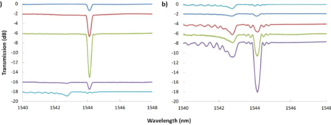
Rapid spectral scanning of slow-growing gratings, which are produced with a low pulse intensity and at a low repetition rate (1 mJ/pulse, 500 fs chirped pulse, 5 Hz), has shown that at the onset of FBG formation, the gratings display transmission spectral characteristics consistent with type I gratings, i.e. little or no cladding mode generation, narrow bandwidth and low scattering loss. This occurs even though the exposure parameters are identical to those used for the fabrication of type II gratings in terms of pulse intensity, duration and fiber-phase mask distance. With continued exposure, the type I-like grating appears to quickly saturate, which is then followed by erasure of the grating spectrum and the onset of a new grating resonance that will eventually develop into a strong type II grating structure.
In the first stage of the process (Fig. 1(a)), a type I grating developed quickly up to a high reflectivity of ~70% which corresponds to a refractive index modulation Δn of~5 × 10⁻⁴ assuming a 4 mm-long grating (as was measured with an optical microscope). Occasionally stronger gratings were recorded up to 90% reflectivity. With continued exposure, the Bragg resonance diminishes and disappears [9]. Prior to the disappearance of the resonance, cladding mode features associated with type II grating spectra begin to appear, becoming stronger as the Bragg resonance diminishes. No noticeable broadband loss can be detected at this stage of the grating growth.
Fig. 1. Evolution of the transmission spectra of (a) type I-like grating and (b) type II grating as a function of laser exposure. Transmission spectral traces are offset vertically for ease of viewing and correspond to increments of 15 laser pulses per trace.
The formation of type II grating spectral features that are observed before the disappearance of the type I-like resonance (bottom trace in Fig. 1(a)) may indicate a competition between type I and type II mechanisms of index change. Type I induced index change with a femtosecond laser has been associated with a positive index change while type II has been associated with a negative index change [13].
In the next stage of the grating growth (Fig. 1(b)), the cladding mode and the fundamental mode of the Bragg resonance grow rapidly with successive pulse accumulation. The grating evolution is accompanied by broadband loss, typically less than 0.5 dB in this case, but can reach a 1 dB loss level or more, depending on the grating strength.
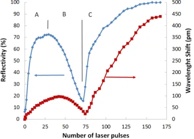
The full evolution of the grating reflectivity and shift in the Bragg resonance during exposure, as was measured with the grating interrogator, is presented in Fig. 2. Stage A depicts the type I-like grating growth until saturation, stage B its decay and erasure, and stage C, the type II grating growth to saturation reaching ~100% reflectivity. Gratings written within each of the three stages of grating evolution have differing behavior when subjected to high temperature annealing.
Fig. 2. Example of changes in grating reflectivity (blue trace) and Bragg wavelength shift (red trace) as a function of laser exposure. Stage A denotes type I-like grating growth to saturation, stage B denotes the type I-like grating erasure and stage C denotes development of a strong type II grating.
3.2 Annealing of stage-A gratings
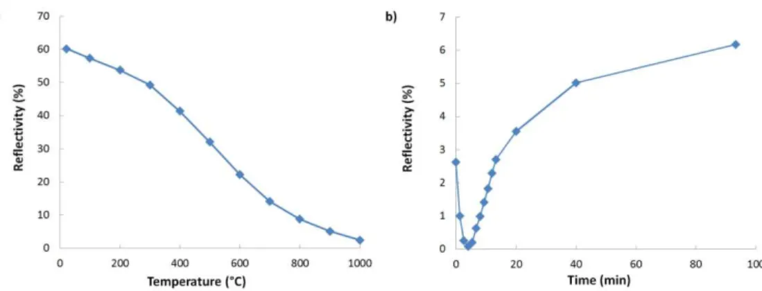
Gratings that were created during stage A of the inscription process (A-grating), display all the spectral characteristics of type I gratings, namely the lack of cladding modes, very low scattering loss and very low side lobes. A 60% reflectivity grating was written using the inscription conditions given above with the exposure terminated before the start of the erasure process. As shown in Fig. 3(a), this grating was isochronally annealed at temperatures up to 1000 °C for 60 min at each temperature. Up to 900 °C, the grating reflectivity decayed in a predicted fashion, stabilizing after about 20 min of isothermal annealing at each temperature. However at 1000 °C (Fig. 3(b)), the reflectivity rapidly disappeared below the detection limit of the measurement system, but then recovered to about 6% and stayed at this level for several hours. It was also observed that during the process of erasure and regeneration the Bragg wavelength remained unchanged within the resolution limit of the measurement system (~10 pm). Although the stage-A grating is spectrally similar to a type I grating, its annealing characteristics, specifically the grating regeneration (Fig. 3(b)), are different from a typical type I grating.
Fig. 3. (a) Change in reflectivity of the stage A-grating during isochronal annealing; (b) evolution of a thermally stable grating as a function of time at 1000 °C.
3.3 Annealing of stage-B gratings
In order to determine the high temperature behavior of stage-B gratings (B-gratings), several of them were inscribed with different numbers of accumulated pulses. One FBG was recorded in the late portion of stage B (i.e., high dosage grating). A second FBG was written close to the first grating using grating inscription parameters needed to produce a typical type I grating [14]. As the annealing behavior of type I gratings is well known, it served as a reference for the annealing behavior of the late stage B-grating. A third grating was written in a separate fiber such that the exposure was terminated just after the initiation of erasure of the type I-like structure (i.e., low dosage grating). The high dosage and the low dosage B-gratings were written with numbers of pulses in the 30- 50 range, with the high dosage B-grating receiving about 25 more pulses in the fiber core compared to that of the low dosage B-grating. Both samples, i.e., the two-grating fiber and the one-grating fiber were then annealed, with the temperature being incremented by roughly 100 °C every hour.
Fig. 4. (a) Grating reflectivity variation as a function of isochronal annealing temperature. Red trace is a standard type I grating, blue trace is the high dosage B-grating, the green trace is the low dosage B-grating; (b) denotes the stabilization of low dosage (green) and high dosage (blue) B-gratings when annealed at 1000 °C.
As expected, the type I grating (red trace in Fig. 4(a)) lost half of its reflectivity around 500 °C and decreased below 2% at 1000 °C. The high dosage B-grating, however, lost its reflectivity more rapidly and was completely annealed at 500 °C. At 600 °C, the grating reflectivity reappeared and grew rapidly to 80% at 1000 °C. In the case of the low-dosage B-grating, complete erasure occurred at 700 °C rather than 500 °C and regrowth at 1000 °C resulted in a 46% reflectivity. The two B-gratings were kept at 1000 °C for tens of hours (Fig. 4(b)). At this temperature the high dosage B-grating stabilized at 70% reflectivity after 150
hours. As far as the low dosage B-grating is concerned, its reflectivity increased to 55% after a couple of hours but then dropped to 45% and stabilized at this level after 50 hours. No further change in reflectivity was measured even after another 100 hours at 1000 °C. As expected, no regeneration of the type I grating was observed.
The initial and the final transmission states of the grating spectral evolutions are presented in Fig. 5. At room temperature (22 °C), the transmission spectral profile of the high dosage B-grating (Fig. 5(a)) was located at 1540 nm. The type I B-grating had a resonance at ~1545 nm (not shown). After 100 hours at 1000 °C, the type I grating was completely annealed and a thermally stable grating was regrown after the complete annealing of the original B-grating. Very little wavelength shift (20 to 40 pm) between the Bragg wavelength before and after annealing of the B-grating was detected, and no broadband loss induced during the annealing process was measured. In Fig. 5(b) the initial (at 22 °C) and final spectra (at 1000 °C) of the low-dosage B-grating are presented. It is observed in these plots that the initial transmission spectra do not possess a significant amount of cladding mode loss especially for the low-dosage B-grating. This is not the case in the final spectra of the gratings where cladding mode coupling is clearly visible.
Fig. 5. (a) The initial transmission spectrum of the high-dosage B-grating with a room temperature resonance at 1540 nm (red trace) and its spectrum at 1000 °C after several hours of annealing at 1000 °C (blue trace); (b) The transmission spectra of the initial room temperature low dosage B-grating (red trace) and its spectrum at 1000 °C after annealing at 1000 °C (green trace).
3.4 Annealing of stage-C (type II) gratings
Gratings that are written with sufficient exposure to reach stage C of the grating evolution also increase their reflectivity during annealing when the temperature is increased from 22 °C to 1000 °C. Several stage-C gratings (C-gratings) with different reflectivity were written and then annealed using the same process that was used for the B-gratings. C-gratings tend to go to 100% reflectivity after annealing even if they are initially created with low reflectivity. It was also observed that there was no strong relation between the observed initial and final reflectivity. Annealing at 1000 °C revealed an unusual behavior where large oscillations in the Δn were observed (growth, erasure, regrowth). After several hours the index modulation stabilized.
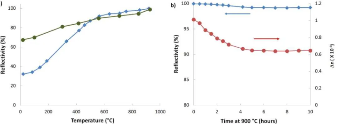
In Fig. 6(a), a low-dosage and a high-dosage C-grating with 30% and 70% reflectivity respectively were isochronally annealed to 900 °C, at which point both devices approached 100% reflectivity. Continued monitoring of the low-dosage C-grating showed stable reflectivity during a lengthy annealing test at 900 °C (Fig. 6(b)). The high dosage C-grating stability showed the same pattern as the low dosage C-grating presented in Fig. 6 (b).
It is difficult to get sufficient insight into the nature of transformations occurring inside C-gratings during annealing based solely on the grating reflectivity evolution since the reflectivity remains close to a 100% level (blue trace in Fig. 6(b)). In this respect, the
evolution of the Δn during annealing is more revealing. By assuming a Gaussian Δn profile along a grating, whose length is estimated at ~4 mm, the Δn can be deduced from the grating reflection spectrum by using a truncated generalized Gaussian apodization function [15]. The Δn (red trace in Fig. 6(b)) is observed to decrease and then stabilize after several hours indicating a more complex annealing process than simply a competition between positive and negative changes in the refractive index, with the positive one being annealed out at high temperature. While the refractive index amplitude seems to increase as the temperature is ramped up from 22 °C to 900 °C (Fig. 6(a)), which may be due to annealing of the type I modification, it is followed by a decrease of the refractive index (Fig. 6(b)) that may be due to either an instability of the type II modification/changes or the presence/generation of a refractive index contribution of a different nature, like stress relaxation, that is affected by the high temperature. To a certain extent, the Δn of B-gratings follows a similar pattern (Fig. 4(b)). The reflectivity of regenerated B-gratings is lower than that of C-gratings, however the former also exhibit a large correction at sustained high temperature before a long-term stability characterized by a smaller Δn is finally reached.
Fig. 6. (a) Isochronal annealing behavior of a low dosage (blue) and high dosage (green) C-grating; (b) Changes in reflectivity (blue) and index modulation Δn (red) of the low dosage C-grating under sustained annealing at 900 °C.
4. Discussion
In general, the evolution of the grating during the writing of type II grating structures and during the subsequent annealing process is the result of the interplay between different types of laser-induced refractive index changes. Simultaneous formation of type I and type II index change is likely occurring, where the type I index change is associated with the formation of color center defects and the type II index change is associated with structural changes. The amount of type II index change per pulse is likely dependent on changes in absorption in the glass that result from previous exposure. In the absence of previous laser-material modification, type I index change is initially dominant (stage A). The peak intensities used however, are consistent with type II grating formation when multiple pulses are absorbed. It is therefore likely that a portion of the index change, even with low numbers of accumulated pulses, is the result of structural changes (type II). As more pulses are absorbed, the proportion of type II index change that is produced from each subsequent pulse becomes larger. This explanation is supported by the initial lack of cladding mode resonances in the grating transmission spectrum (Fig. 1(a)), which are a characteristic feature of type II gratings. At a certain moment during the growth of the type I grating, a type II grating structure is induced, either as a result of its natural evolution, or as a result of this incubation effect caused by the growth of the type I grating structure [16]. For instance, it is well known that thermally stable form birefringent nano-gratings in silica glass can be produced if the material has absorbed a sufficient number of incubating femtosecond laser pulses [17]. It is possible that a similar process is occurring here.
If it is assumed that the type I grating consists of a positive refractive index change and the type II grating has a negative refractive index change, then the resulting grating spectrum becomes the sum of the contributions of each type of index change. In this simplified model of two-grating structures evolving simultaneously, either independent of each other or in a causal relation, a situation can be considered when the type II grating formation starts later but proceeds at a greater speed than that of the type I grating (stage A in Fig. 2). In this scenario, the grating reflectivity will saturate early when the two grating structures reach the same growth rate and will decrease when the growth of the type II grating structure takes precedence over the type I structure (stage B in Fig. 2). Finally, the reflectivity drops to zero when the index modulations pertinent to the type I and II changes become equal and thus cancel each other.
The small amount of light coupled to the cladding mode (purple trace in Fig. 1(a)) in the B-stage confirms the presence of a type II grating structure that, even if it is compensated at the Bragg resonance by a type I structure, still couples light to the cladding. The point in the irradiation process when the reflectivity reaches a minimum due to this compensation coincides with the complete erasure of the Bragg resonance. After this point, the formation of a type II Bragg grating is believed to continue at a very high pace, increasing the reflectivity at the Bragg resonance wavelength (stage C in Fig. 2).
If the grating evolution is terminated during the second exposure stage, i.e. after the formation of the type II grating has been initiated but before the Bragg resonance has been erased (stage B in Fig. 2), the grating can be annealed to remove the type-I refractive index modification, thus leaving a very low loss type II grating that is stable at high temperatures up to 1000 °C as shown in Fig. 4. When during the annealing process, the amount of positive refractive index balances the level of the negative refractive index that presumably remains stable, the grating reflectivity reaches zero. Further erasure of the positive refractive index results in growing reflectivity due to the higher contribution of the negative refractive index and will appear to be like a grating regeneration process. Evidence that the type I component of the refractive index can indeed be annealed is supported not only by the increase in the grating reflectivity but also by the fact that for B-gratings the Bragg resonance wavelength after annealing is systematically shorter than before annealing by about 20-40 pm.
However, this model cannot explain the evolution of the Bragg wavelength during the stage C of the exposure (red trace in Fig. 2). The C-grating is similar to the thermally stable type II FBG reported earlier that produced higher order Bragg resonances [6]. The C-grating is seen to undergo a positive wavelength shift of the Bragg resonance implying that there is a positive index change, which is not consistent with a simple two positive/negative refractive index model. The erasure of the type I grating during stage B of the inscription process could be caused by the re-arrangement of the glass structure due to the emergence of the type II grating rather than by a simple positive/negative cancelation of the effect of two superimposed structures. Neither the positive/negative refractive index model nor the re-arrangement of the glass structure can explain the increased transfer of the signal to the cladding modes during annealing.
The high temperature resilient FBG that emerges as a result of annealing of a B-grating, may appear to be related to the previously reported thermally regenerative UV grating [4] as a similar sequence of annealing steps is required to create it. However, unlike other regenerated gratings, the resultant grating in this case has a much higher Δn, requires no hydrogen loading or specialty fiber, nor does it exhibit a significant wavelength shift. Also, the initial grating in this case, often referred to as a seed grating in the regenerative process, is relatively weak with only 20-50% reflectivity as compared to more than 99.9% reflectivity reported for the traditional regeneration [4]. Moreover, the regenerative temperature of 500 °C is significantly lower than regenerative temperatures previously reported [18]. Unlike the typical regenerated grating, which seems to be the result of stresses that are formed or relaxed during the annealing process of the seed grating, the final thermally stable grating structure presented
here seems to arise from the elimination through annealing of an unstable grating structure that is inscribed during the first stages of the process.
For the practical purposes of creating low loss, high temperature stable Bragg gratings, the grating structure formed during stage B is the most promising since the gratings generated in stage A of the process are predominantly of the type I and hence unstable at high temperature, while the gratings formed in stage C are affected by broadband scattering loss.
5. Conclusion
This paper presents a novel inscription/annealing process that produces high reflectivity and very low insertion loss Bragg gratings in silica-based fibers that are stable up to 1000 °C. Although the annealing behavior mimics the evolution of previously reported regenerated gratings, the much higher reflectivity of the final grating is most likely the result of competing annealing behaviors of type I versus type II grating structures present in the fiber. The resulting high-temperature-stable low-scattering-loss gratings are ideally suited for distributed sensing applications based on FBG arrays for harsh environments.