Publisher’s version / Version de l'éditeur:
Technical Note (National Research Council of Canada. Division of Building Research), 1973-10-01
READ THESE TERMS AND CONDITIONS CAREFULLY BEFORE USING THIS WEBSITE.
https://nrc-publications.canada.ca/eng/copyright
Vous avez des questions? Nous pouvons vous aider. Pour communiquer directement avec un auteur, consultez la première page de la revue dans laquelle son article a été publié afin de trouver ses coordonnées. Si vous n’arrivez pas à les repérer, communiquez avec nous à [email protected].
Questions? Contact the NRC Publications Archive team at
[email protected]. If you wish to email the authors directly, please see the first page of the publication for their contact information.
NRC Publications Archive
Archives des publications du CNRC
For the publisher’s version, please access the DOI link below./ Pour consulter la version de l’éditeur, utilisez le lien DOI ci-dessous.
https://doi.org/10.4224/20358787
Access and use of this website and the material on it are subject to the Terms and Conditions set forth at
Preliminary Analysis of Structure-Ground Interaction for Seismic
Design of a Nuclear Reactor Structure
Rainer, J. H.
https://publications-cnrc.canada.ca/fra/droits
L’accès à ce site Web et l’utilisation de son contenu sont assujettis aux conditions présentées dans le site LISEZ CES CONDITIONS ATTENTIVEMENT AVANT D’UTILISER CE SITE WEB.
NRC Publications Record / Notice d'Archives des publications de CNRC: https://nrc-publications.canada.ca/eng/view/object/?id=bf45795a-ed8b-438b-9527-db851fc7a47b https://publications-cnrc.canada.ca/fra/voir/objet/?id=bf45795a-ed8b-438b-9527-db851fc7a47b
DIVISION OF BUILDING RESEARCH
No.
NATIONAL RESEARCH COUNCIL OF CANADA
.li
'fEClHIN JICAlL
580NOTJE
'.,PREPARED
J. H. Rainer CHECKED BY T.D.N. APPROVED BY A.G.W.
PREPARED FOR
SUBJECT
セ October 1973
Mr. E. Smith, Atomic Energy of Canada Ltd., Sheridan Park, Onto
PRELIMINARY ANALYSIS OF STRUCTURE-GROUND INTERACTION FOR SEISMIC DESIGN OF A NUCLEAR REACTOR STRUCTURE
The following is a preliminary analysis of the effects of
inter-action of the structure with the ground under seismic loading. Various
approximations and assumptions had to be made either because more definitive information was not available or there was insufficient time for a more exact analysis.
This approximate treatment indicated the important parameters involved and what further steps are required for a more rigorous
treat-ment. The methods contained herein should not be used for final design
without a critical evaluation of their accuracie s and applicability to the structure at hand.
It should be noted that this analysis does not consider the amplification of ground motion due to deep soft soil deposits.
DATA
Structure Dimensions
Diameter of circular rigid base
=
156 ft (47.5 m)Height = 175 ft (53.3 m)
C. G. at approximately mid-height = 26.7 m
Weight of structure = 50,000 tons approx. (50,000,000 kg) Estimated natural period of rigid base structure,
T
=
0.2 sec.... -2-Soil Constants Winkler foundation, k
=
0.8 kg/ cm3 v k H = 0.6 kg/cm 3Boussinesq foundation should also be used
STRUCTURAL AND FOUNDATION PROPERTIES
1. Determination of Natural Frequencies
Vertical stiffness K v = Area· k v
セ
==:ct
47 . 5イセ
= Area = 4 "4-Rocking stiffness K V=
1772 x (0. 8) x 10,000 = 14,200,000 kg/ cm=
13,900,000,000 N/m Horizontal stiffne s s K H=
l772xO.6xlO,000 K H=
10,630,000 kg/ cm=
10,430,000,000 N/m TTr4=
0 8 TT(4750}4=
k v· I=
k v . 4 . x 64 Ka
=
20 x 1012 kg cm/rad=
1.96 X 10¹² Nm/rad Translational frequency 10.63 X 106 x 982 =JZ09
=
14.5 rad/ sec 50,000,000 or f H = 2.31 Hz T H=
0.433 sec. Rocking FrequencyMass moment of inertia of structure: asswne uniform mass distribution
w = 50,000,000 - 19,700 kg/m2
.
' '.
I -3-bd3 47.5 x (53.3)3 = 3 .w= 3 .19,700 1=
4.73 x 1 010kg zn2 W _j
K 1e
=
196 x 1010 Nzn=
e-
4.73 x 10¹⁰ kg zn2fa
= 1. 03 Hz or Te
=
o.
97 sec. Structural Frequency T = 0.2 sec=
5 Hz = 31.4 rad/sec oCoznbined Coupled Frequency
T2 = T2
+
T2
+
T 2o
H
e
= 0.22
+
0.4332+
0.972 =1.
17.}4T:"5 •
6.45 rad/ secT = 1.08 sec or f
=
0.925 Hz = 5.92 rad/ secReznarks
As can be seeri, the dynaznic properties are coznpletely dozninated by the rocking znotion, with the translation providing a sznall znodification. For all practical purposes the structural deforznability can be neglected for purposes of investigating the effect of ground-structure interaction.
A further consequence of this observation is that the rocking frequency should be deterznined to a higher degree of accuracy than was
possible frozn the above data. A znore accurate deterznination of the
znass znoznent of inertia is required.
There are now three resonance frequencies, in accordance with the three degrees of freedozn of rotation, base translation, and
structural deforznation. As an initial approxitnation it is sufficient to
consider the first znode only, the one having the previously calculated
period T
=
1.08 sec.2. Daznping
An approxitnate daznping coefficient can be coznputed frozn half-space theory.
"
•
セNwr
a=
oV
s-4-v
=
shear wave velocity of ground.s
asswne V = 1000 fps (mediwn soil)
s a
o
= (5.92) (78) = 0 46
1000· •
The damping ratio in rocking is
C
R
B 50,000,000 = 1.95 X 103 X 23.73 1.93 h=
(_)2 = I. 122=
1.25 rO!I
セ A = = 0.0195= .02 R 2 (1. 93 x 1.25 x 2. 7)1/2 A=
2% of critical RThus an approximate value for rocking damping is 2 per cent of
critical due to radiation of energy into the half-space. To this can
be added hysteretic ュ。エ・セゥ。ャ damping of the soil. At the moment this
is difficult to evaluate, but with more investigation and literature
search some justifiable value could be derived. A rough estimate of
damping for soil material is between 2 and 5 per cent, additive to the radiation damping.
As the damping in the rocking mode is rather low, it becomes
a dominant design parameter. Therefore for final design, a more
thorough analysis of the frequency response curve for the entire system would be justified.
The motion of the structure in the horizontal direction is highly damped and this will somewhat influence the amount of over-all damping. A quantitative answer can be obtained only be evaluating the transfer
function of the system. The contributions of the higher modes can
also be obtained from a detailed study of the transfer function of the entire system.
•
Further information needed for more accurate evaluation of -5-ground-structure interaction effects include:1. A more accurate description of the mass distribution of structure.
2. More information about soil, especially modulus. type, etc.
3. Information of expected earthquake motion.
4. Detailed study of transfer function of the system.
3. Mode shapes
U sing the approximations for an undamped system, the relative
modal 。ューャゥエオセ・ウ are given by Balan et ale
X B. WH;2
=
(h8) We 2=
X. W 2 0 X Bw
2 0 31. 42 4.7=
セR=
14.52=
X W 2 h8 0 31. 42 23.8=
wa
=
6.452=
Xe
•
X B ,4.7=
Z3.8
=
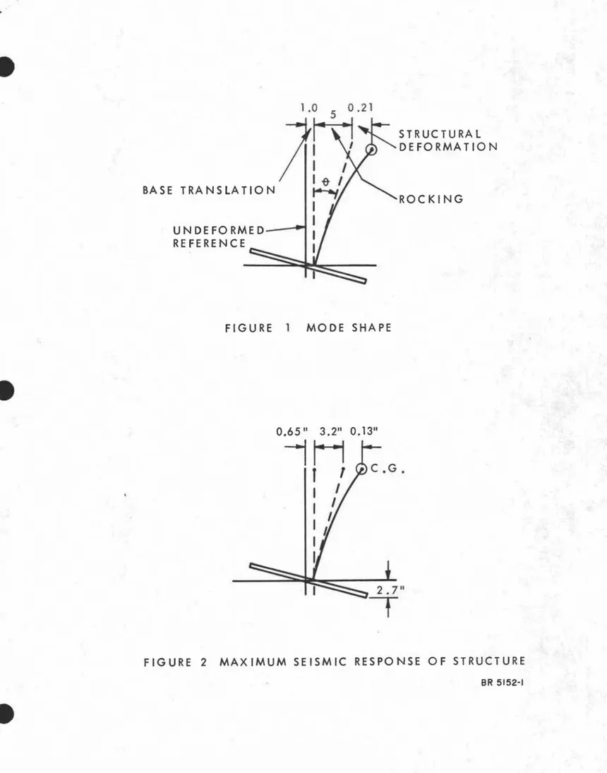
0.2 h8 Modal ratios: X B : ィセ : X=
1:5:0.21The mode shape is sketched in Figure 1. These modal ratios are
approxi-mate and are subject to inaccuracies because of non-proportional damping. More accurate answers can be obtained from the transfer function
analysis.
APPLICATION IN SEISMIC DESIGN
•
As the system is dominated by the rocking mode, for preliminary
design it is satisfactory to consider its effect alone. One can now treat
the entire system as a single -degree -of-freedom (S. D. F.) oscillator with
natural period T
=
1.08 sec or frequency f=
0.925 Hz, and damping ofA = say 5 percent (2 per cent radiation damping, 3 per cent hysteresis
damping). The forces determined from response calculations or
.'
-6-at the centre of gravity of the structure during th-6-at disturbance. The
deformations determined from those re sponse calculations are the total deformations at the C.G., i.e., having a modal amplitude of
1.0+ 5.0 + 0.21
=
6.2 (relative).1. Deformations of structure
For a spectral re sponse value of
S
=
25 in! secv
SD
=
4 in.SA
=
0.40 gThe following deformations are obtained (Figure 2):
Horizontal, at C. G. : 6
セ
2=
o.
65 in. 4 6.2 x 5=
3.2 in. 4 6.2 x 0.21=
0.13 in.Vertical movement at edge of mat:
3.2 x
セセ
= 2.7 in.To reduce these deformations the following seem. possible:
(a) refine the determination of damping; this may yield a higher
value of
A;
(b) stiffen the soil foundation (pile s, com.paction, etc.);
(c) extend the base to provide greater foundation-soil stiffness.
2. Vertical interaction of structure with ground
Vertical natural frequency
13, 900 x I 06 =
J
278=
1 6. 7 r ad/ sec50 x 106
fv
=
2.7 HzThis is a low vertical resonance and may play some role in the
seismic design. The damping in the vertical direction is substantial,
however. With the aid of machine vibration analogue (Richard,
.' 7 -Bz =
I-v
M セ 0.7 50,000,000 0.33p;-a
- - x=
4 4 2 x 103 x 23.73 0 D = 0.425=
0.425=
0.74JBZ
.[":33
Therefore the damping coefficient A
=
74 per cent of critical, i. e. ,it is ahnost critically damped, considering only geometric damping. To
this could be added material damping of the soil. It may therefore be
concluded that vertical motion of the structure will not be amplified and, in fact, may be reduced as compared to the vertical motion of the ground.
ALTERNATIVE PROPOSAL: FRICTION PILE FOUNDATION
Reinforced concrete precast friction piles, 180 ft long, 16 in.
diameter. Number of piles: 758; design load: 260 kips/pile.
An estimate of stiffness has to consider the whole pile group. The properties of the individual pile become rather secondary in character.
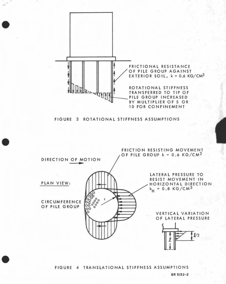
1. Assumptions
Rocking
Assume piles transfer load to tip of pile group. Soil stiffness
increases by a factor of perhaps 5 to 10 due to overburden
confine-ment. In addition, peripheral friction of pile group and soil
con-tained therein will act against external soil. Assume that the
vertical spring stiffness in friction is the same as the spring stiffness for the Wiilkler foundation in the horizontal direction at the surface, k
H = 0.6 kg/cm
3 (Fi.gure 3).
Horizontal translation
Assume that the entire soil cylinder within the perimeter piles
. acts against the exterior soil. In addition, frictional forces will
be mobilized at right angle s to direction of motion. Owing to pile
deformations this pre s sure will be distributed in a triangular
manner from the butt of the pile to, say, one half its length. In
the direction of motion, assume the value for the
Winkler-foundation constant in compression, k v = 0.8 kg/cm3
; in friction
assume the constant in shear, kH = 0.6 kg/cm3 • The pressure
distribution is assumed to vary sinusoidally from one end of a diameter to the other (Figure 4).
.
''.
-8-2. Calculation of Constants
Rocking Motion:
Moment of inertia of peripheral ring = 1/2 polar moment of intertia
nr3
=
1/2 (nD r 2)=
4
3
Total rotational stiffness
=
ョセ
• depth x 0.6+
5 x (rotational platestiffness)
=
n(2375)3 x 6000 x 0.6+
5 (20 x 1012 ) kg cm/ rad4
=
130 X 1012 kg cm/radK
e
= 1 3 x 10¹² Nm/ r adRevised moment of inertia of structure: centre of rotation is likely
to shift downward from base to, say one third the pile length.
Old I
=
4.7 x 10¹⁰ kg m 2New 1= 12.6 x 10¹⁰kg m 2
Rocking frequency for multiplier of 5 for base stiffne ss:
=
13 x 1012 Nm/rad=
jfOO
=
10 rad/secW e I2. 6 x 10¹⁰kg m2
or f
e
= 1.6 HzT'e = 0.62 sec.
Horizontal motion:
Equivalent spring stiffne s s = O. 7 x O.8 x 2r x depthj 4
+
2(0.7) x 0.6 x 2r x depth/4 K H = 10 x 10 6 kg/cm or K H = 10 x 10 9 N/mAdditional soil inertia mass in horizontal direction: nD2
=
T
x depth/4 x 110 Ib/ft3n(156)2
=
4 x 180/4 x 110=
95,000, 000 Ib=
40, 000 tons·'
•
-9-Whether this additional soil mass is fully active in the earthquake
response is somewhat questionable. Consequently calculations will
be performed with and without considering this soil mass.
Translational frequency: 10 X 10 9 N/m
=
10.5 rad/ sec 90 x 106 kg or f H=
1.7 HzT = 0.6 sec with soil mass
H T
H
=
0.44 sec without soil mass (14.1 rad/sec).Combined coupled period:
T2 = 0.22
+
0.62+
0.622T
=
0.88 sec or f=
1.12 HzThe periods for the various assumptions are summarized in Table 1.
Damping:
The over-all damping coefficient can probably be increased to 10 per cent because of the large surface areas over which relative deformation occurs and consequently where energy will be dissipated.
50/0 is certainly quite conservative.
3. Seismic Response
Using the same procedure as was used above, the seismic response for the various alternatives considered are presented in Table II.
DISCUSSION OF RESULTS
It is likely that the values of XB are on the large side since higher lateral soil stiffness can probably be mobilized.
In comparing the results for the various assumptions it is
evident that where the rocking component has been reduced, the horizontal
motion has increased. This can be expected since the rocking stiffness
has been increased relative to the horizontal stiffness. The total
spectral displacement has to be accommodated by the available degrees of freedom.
"
-·10-Relatively rough assumptions have been made in arriving at the
over -all pile foundation stiffness. DBR colleagues in the Geotechnical
Section. supported the assumption of group action proposed in this
Note as being reasonable. However, there is considerable latitude
in the choice of the numbers used to describe the soil properties. With the questionable improvement derived from a friction pile foundation and the other associated problems of settlement, has the possibility of partial submergence of the structure been investigated?
This would be along the nature of a "floatingIt structure in the soil. The
earthquake response of a structure substantially surrounded by proper
backfill could then be greatly reduced. The contents of such a
structure would then be subjected essentially to the ground motions. One assumption that should be further investigated is the location of the centre of rotation and the subsequent calculation of 1. Raising this centre of rotation would decrease the combined period,
slightly reduce the total spectral displacement, and decrease the
relative amount of rocking. The relative proportion of horizontal
.'
TABLE I
SUMMAR Y OF PERIODS, SECONDS
Horizontal Rotational Com.bined
Case TH, sec T, seccp T, sec
l. Mat on soil 0.43 0.97 1. 08
2. Friction Piles
Multiplier 5
a) with soil inertia 0.6 0.62 0.88
b) without soil inertia 0.44 O. 62 0.72
Multiplier 10
c) with soil inertia 0.6 0.44 0.77
e
e
e
"TABLE II
SUMMARY OF RESPONSE CALCULATIONS
Over-all Spectral Base Rocking Structural Modal
Ampli-DaInping Displacement Displacement Displacement Displacement tude Ratios
Case Description
%
Critical SD ' in. セN in. hcp. in. X. in. XB:hS:x1 Mat on grade 5 4 0.65 3.2 0.13 1:5:0.21
T
=
I sec2 Friction Piles
a) soil mass included 5 3.5 1. 65 1. 65 0.18 1:1:0.I.l
T
=
0.88 sec 10 2.5 1.2 1.2 0.13b) soil mass excluded 5 3 1.0 1.9
o.
1 1:2:0.1T
=
0.72 sec 10 2 0.65 1.3 0.06c) soil mass included 5 3 1.9 0.9 0.19 1:0.5:0.1
T
=
0.77 sec 10 2 1.3 0.6 0.13d) soil mass excluded 5 2.5 1. 15 1. 15 0.23 1:1:0.2
"
BIBLIOGRAPHY
Balan, S., lfriIn, M., and Pacoste, C. Dynamic Equivalent of
Antiseismic Structures Considering the Deformability of the
Foundation Ground. Proc., Internat. Symp. on the Effects
of Repeated Loading of Materials and Structures, RILEM,
Mexico City. 15-17 Sept. 1966.
Rainer, J. H. Method of Analysis of Structure -Ground Interaction
in Earthquakes, Nat. Res. Council of Canada, Div. Bldg. Res.,
Technical Paper No. 340, Ottawa, April 1971. (NRC 11920)
Rainer, J.H. Structure-Ground Interaction in Earthquakes. J.
Eng. Mech. Div.• ASCE, Vol. 97, No. EM5, Oct. 1971,
p. 1431-1450. (NRC 12054)
Richart, F. E. Jr., Hall, J. R. Jr., and Woods, R. D. Vibrations
of Soils and Foundations, Prentice Hall, 1970.
Roesset, J., Whitman, R. V .• and Dobry, R. Modal Analysis for
Structures with Foundation Interaction. J. Struc. Div.,
ASCE, Vol. 99, No. ST3, March 1973, p. 399-416.
Sarrazin, M.A., Roesset, J.M., and Whitman, R. V. Dynamic
Soil-Structure Interaction. J. Struc. Div., ASCE, Vol. 98,
UN DE FO RME D---REFERENCE
FIGURE 1 MODE SHAPE
STRUCTURAL DEFORMATION ROCKING 0.65II 3.211 0.1311
セh
,
1
I
I
I
I
I
I
l
I
I
2.711t
FIGURE 2 MAXIMUM SEISMIC RESPONSE OF STRUCTURE
I I
セ
t
FRICTIONAL RESISTANCE1 V O F PILE GROUP AGAINST
• EXTERIOR SO IL, k
=
0.6 KG/CM3I
セiャGャGGエ
t
ROTATIONAL STIFFNESS,lilt.Ll
QNQセMNZ」
n'llIlr..Ll'rrr_ _
TRANSFERRED TO TIP OF".!..I I'l. _ P IL E G R0 UP INC REA SED
BY MULTIPLIER OF 5 OR
10 FOR CONFINEMENT
FIGURE 3 ROTATIONAL STIFFNESS ASSUMPTIONS
.t!2
VERTICAL VARIATION OF LATERAL PRESSURE LATERAL PRESSURE TO RESIST MOVEMENT IN HORIZONTAL DIRECTION k H = O. 8 KG / C M3FRICTION RESISTING MOVEMENT
OF PILE GROUP k
=
0.6 KG/CM3 DIRECTION OF MOTION•
P LA N VIEW: CIRCUMFERENCE OF PILE GROUPFIGURE 4 TRANSLATIONAL STIFFNESS ASSUMPTIONS