Publisher’s version / Version de l'éditeur:
Canadian Journal of Civil Engineering, 28, December 6, pp. 969-978, 2001-12-01
READ THESE TERMS AND CONDITIONS CAREFULLY BEFORE USING THIS WEBSITE. https://nrc-publications.canada.ca/eng/copyright
Vous avez des questions? Nous pouvons vous aider. Pour communiquer directement avec un auteur, consultez la première page de la revue dans laquelle son article a été publié afin de trouver ses coordonnées. Si vous n’arrivez pas à les repérer, communiquez avec nous à [email protected].
Questions? Contact the NRC Publications Archive team at
[email protected]. If you wish to email the authors directly, please see the first page of the publication for their contact information.
NRC Publications Archive
Archives des publications du CNRC
This publication could be one of several versions: author’s original, accepted manuscript or the publisher’s version. / La version de cette publication peut être l’une des suivantes : la version prépublication de l’auteur, la version acceptée du manuscrit ou la version de l’éditeur.
For the publisher’s version, please access the DOI link below./ Pour consulter la version de l’éditeur, utilisez le lien DOI ci-dessous.
https://doi.org/10.1139/cjce-28-6-969
Access and use of this website and the material on it are subject to the Terms and Conditions set forth at
Structural performance of sliplined watermain
Zhao, J. Q.; Daigle, L.
https://publications-cnrc.canada.ca/fra/droits
L’accès à ce site Web et l’utilisation de son contenu sont assujettis aux conditions présentées dans le site LISEZ CES CONDITIONS ATTENTIVEMENT AVANT D’UTILISER CE SITE WEB.
NRC Publications Record / Notice d'Archives des publications de CNRC:
https://nrc-publications.canada.ca/eng/view/object/?id=dcd5ad85-e9ab-40a6-8e46-935b5447a410 https://publications-cnrc.canada.ca/fra/voir/objet/?id=dcd5ad85-e9ab-40a6-8e46-935b5447a410Structural performance of sliplined watermain
Jack Q. Zhao and Lyne Daigle
Abstract: Rehabilitation of a watermain by grouted sliplining is usually carried out when the existing pipe is only par-tially deteriorated. Although designs that neglect the structural contributions from the existing pipe and the grout are generally conservative, the performance of the rehabilitated pipe needs to be better understood for effective design and management of buried water pipes. Presented in this paper is a practical method for the determination of load sharing and circumferential stresses in a sliplined pressure pipe. The laboratory tests show that the load carrying capacity of a cast iron pipe increases substantially after it is sliplined and grouted. Results also indicate that the eccentricity between the host pipe and the inserted pipe and the direction of eccentricity have an impact on the rupture load of the sliplined pipe. The effects of the host pipe wall thickness and the grout strength are also discussed. Although the method is based on a pressurized watermain, it can be used to assess the load carrying capacity of a non-pressurized pipe such as a sewer pipe. The use of this method is demonstrated through an example.
Key words: performance, sliplining, watermain, circumferential stress, load sharing, grout, service life.
Résumé : La réhabilitation des conduites d’eau par la méthode de tubage avec injection de coulis de ciment dans l’espace annulaire est normalement entreprise lorsque la conduite existante est partiellement détériorée. Bien que les conceptions négligeant les contributions structurales de la conduite existante et du coulis de ciment soient généralement conservatrices, la performance des conduites réhabilitées requiert d’être mieux comprise pour une conception et une gestion efficace des conduites d’eau souterraines. Cet article présente une méthode pratique pour la détermination du partage des charges et des contraintes circonférentielles des conduites sous pression réhabilitées par tubage. Les essais en laboratoire montrent que la capacité portante d’une conduite en fonte grise s’accroît substantiellement après la réha-bilitation par tubage et l’injection de coulis de ciment. Les résultats indiquent aussi que l’excentricité entre la conduite hôte et le tuyau inséré ainsi que la direction de l’excentricité ont un impact sur la charge de rupture de la conduite ré-habilitée. Les effets de l’épaisseur de la paroi de la conduite hôte et de la résistance du coulis de ciment sont aussi dis-cutés. Bien que la méthode soit basée sur des conduites sous pression, elle peut être employée pour évaluer la capacité portante des conduites non pressurisées, telles que des conduites d’égout. L’utilisation de cette méthode est démontrée par le biais d’un exemple.
Mots clés : performance, réhabilitation par tubage, conduite d’eau, contraintes circonférentielles, partage des charges, coulis de ciment, durée de service.
Zhao and Daigle 978 Introduction
Sliplining is one of several trenchless techniques that can be used for the rehabilitation of buried municipal pipelines. It involves pulling or pushing a liner pipe into an existing host pipe that is in need of rehabilitation as a result of its de-graded hydraulic or structural performance. The liner pipe usually has a maximum diameter that is about 10% smaller than the host pipe to allow easy installation (PPI 1973; Sclairpipe 1996).
Common practice in designing sliplined rehabilitation is to neglect the structural contributions of the existing host pipe and the grout (Hickle and Glasgow 1997). The new
liner pipe is designed on the premise that the existing host pipe is fully deteriorated. According to the definitions for “fully” and “partially” deteriorated pipes given by Standard F 1698-96 (ASTM 1996), it is usually appropriate to con-sider rehabilitating an existing watermain long before it reaches the fully deteriorated state, thus preventing unac-ceptable numbers of breaks in the main. A partially deterio-rated pipe can still support the soil and surcharge loads throughout the design life of the rehabilitated pipe because of the load bearing strength and the stabilized pipe–soil sys-tem.
This common practice leads to conservative designs as it oversimplifies the true performance by neglecting the signif-icant contributions from the grout and the existing host pipe. A better understanding of the performance of the rehabili-tated pipe is needed. Before they can take a proactive and in-tegrated approach to maintaining acceptable levels of service of their underground watermains, municipal engineers need reliable tools to assess performance and predict the service life of both the existing and rehabilitated pipes. When adequate bonding exists at the interfaces between the grout and the liner pipe, and between the grout and the existing host pipe, the rehabilitated pipe becomes a composite pipe. This situation represents the “best case,” as illustrated by
Can. J. Civ. Eng. 28: 969–978 (2001) © 2001 NRC Canada
969
DOI: 10.1139/cjce-28-6-969
Received October 12, 2000. Revised manuscript accepted October 4, 2001. Published on the NRC Research Press Web site at http://cjce.nrc.ca on November 23, 2001.
J.Q. Zhao1and L. Daigle. Institute for Research in Construction, National Research Council Canada, Montreal Road, Ottawa, ON K1A 0R6, Canada.
Written discussion of this article is welcomed and will be received by the Editor until April 30, 2002.
McAlpine (1997). In his study, the design of a profiled PVC-grout-reinforced concrete (host) composite pipe system was carried out using the transformed section method. How-ever, the eccentricity of the liner pipe from the host pipe is not considered in the study, although the annulus gap, which ranges from 12 to 75 mm, is mentioned.
When bonding at the interfaces cannot be relied upon, the rehabilitated pipe system is a “pipe-within-a-pipe” system (i.e., three independent rings — host pipe ring, grout ring, and liner pipe ring). This is the “worst case” system and is defined as Type II lining by WRc (1994). In real applica-tions, a sliplined pipe system with grouting may lie between the best and the worst cases.
This paper presents a method for assessing the perfor-mance of the liner pipe, as well as the structural contribu-tions of the grout and the existing host pipe, in a pipe-within-a-pipe system that is treated as a plane strain prob-lem. The existing watermain pipe to be sliplined is assumed to be partially deteriorated. This method is validated with the results from laboratory testing of a sliplined test pipe and is demonstrated in a practical example of a 915 mm diame-ter cast iron wadiame-termain sliplined with a DR 17 HDPE pipe. The effects of eccentricity and of grout strength on the per-formance of the rehabilitated pipe are discussed. The results are discussed with an emphasis on the remaining service life of a sliplined watermain with a grouted annulus. The method can provide useful information to engineering professionals in utilizing reliability-based methodologies to predict the re-maining service life of a watermain (Flourentzou et al. 1999; Aarseth and Hovde 1999; Kleiner 2000).
Load sharing — theoretical analysis
Circumferential stresses in a buried pipe consist of hoop tension due to internal hydrostatic pressures and ring bend-ing as a result of external soil and surface traffic loads. The same stress components exist in a sliplined watermain, but the level of stresses in each pipe ring depends on the dimen-sions and properties of the ring. The trenchless sliplining technique allows the insertion of a liner pipe and annular grouting while the host pipe is under continuous external
soil loads. As a result, the host pipe takes the full external soil load before, during, and after construction. Assuming a uniform wall thickness, hoop tensile stresses due to an inter-nal pressure are the same at all positions along the circum-ference, whereas ring-bending stresses due to an external load vary along the circumference and across the wall thick-ness (Fig. 1). In addition to hoop tension and ring-bending, the pipe rings are subjected to thrust and shear under exter-nal loading. The thrust and shear are critical when the pipe is depressurized (or in the case of a gravity sewer pipe). Hoop stresses and ring-bending stresses are, in most cases, the governing design criteria (ASCE 1984). In a grouted sliplined watermain pipe, the stability of the liner pipe is much enhanced by the grout and the host pipe, which is sup-ported by the surrounding soil. Therefore, thrust and shear stresses due to external loading can be neglected.
Hoop tensile stresses in the liner pipe, the grout ring, and the host pipe can be determined from the strain compatibil-ity requirement in the circumferential direction and the force equilibrium of the pipe system. To facilitate the analysis of sliplined pipes, the following assumptions are made. 1. The liner pipe and the host pipe are concentric. 2. The liner pipe, the grout, and the host pipe are within
their elastic ranges under the expected loading condi-tions.
3. No bonding exists at the interfaces between the host pipe and the grout, and between the grout and the liner pipe. Recent laboratory shear tests show (Zhao et al. 2000) that the bond strength was of the order of 0.5 kPa at the interface between the HDPE pipe and grout, and of the order of 0.5 MPa at the interface between the cast iron and grout. The latter is understandably of a higher order of magnitude because of a greater degree of roughness at the cast iron–grout interface.
4. There is no gap at the interfaces between the three pipe rings.
5. Each pipe ring in the sliplined composite pipe behaves as a thin-walled ring (t/D << 1).
The effects of the above assumptions are discussed with the results of the laboratory tests later. The liner pipe, the grout ring, and the host pipe are designated by subscripts 1, 2, and 3, respectively. Subscript int stands for internal load-ing. The three concentric rings, when subjected to internal hydrostatic loading, undergo expansion in the radial and cir-cumferential directions. Since they are against one another, the compatibility of deformation in the radial and circumfer-ential directions requires that the angular increase in all three rings must be equal. Also, the force equilibrium re-quires that the sum of all the internal forces in the three rings must equal the applied loading. The hoop tensile stress,σ1,int, in the liner pipe that satisfies these requirements is given by [1] σ1 2 1 1 2 2 1 3 1 1 1 ,int = + + E E D D t t E E D D t t 1 3 3 1 × D t p 1 1 2 ( int) Fig. 1. Stresses in the walls of sliplined watermain pipe: (a) due
to external soil loading, (b) due to internal loading, (c) due to surface traffic, and (d) resultant.
© 2001 NRC Canada
Zhao and Daigle 971
where E is the modulus of elasticity, D1 is the mean diame-ter of the HDPE pipe, t1is the wall thickness, and pintis the
internal pressure.
Similarly, the equations for the hoop tensile stresses in the grout ring and the host pipe are given by
[2] σ2 1 2 2 1 1 2 3 2 1 1 ,int = + + E E D D t t E E D D t t D t p 2 3 3 2 1 2 2 ( int) [3] σ3 1 3 3 1 1 3 2 3 1 ,int = + E E D D t t E E D3 2 2 3 1 3 1 2 D t t D t p + ( int)
If we define a rigidity factor,ξ, as Et/D, then eqs. [1]–[3] can be expressed by one equation as
[4] σ ξ ξ ξ ξ j j j D t p j ,int = int; , , + + = 1 2 3 1 2 1 2 3
Equation [1] can be rewritten in terms of rigidity factors as [5] σ ξ ξ ξ ξ 1 2 1 3 1 1 1 1 1 2 ,int = int + + D t p
As indicated by eq. [5], the hoop tensile stress in a pipe ring depends on the rigidity factors of the three pipe rings. For example, if the rigidity factor for the liner pipe is much greater than for the grout and the host pipe, the last two terms in the denominator in the parentheses will have little effect on the stress in the liner pipe. Then, the equation re-duces to the familiar form of
[6] σ1 1 1 2 ,int = int D t p
which is Barlow’s equation (Moser 1990) for calculating the hoop tensile stress of a thin-walled pipe due to internal load-ing. The definition of a thin-walled vessel or pipe is that the ratio t/D is sufficiently small so that the variation in stress across the wall thickness can be neglected (Beer and Johnston 1985; ASCE 1984). Heger (ASCE 1984) discussed the impact of the ratio D/t. For D/t = 10 and 20 (or t/D = 20% and 10%), the error in using the thin-walled theory is 7% and 3.4%, respectively. Since the three rings form a pipe-within-a-pipe system, each ring acts as an independent thin-walled ring. For a fully composite pipe, however, the three rings act together as one ring and the assumption of thin-walled pipe may introduce unacceptable errors when the overall D/t is less than 10 (or t/D > 10%).
Equation [6] applies to the liner pipe when there is a gap between the liner pipe and the grout and when the host pipe
is fully deteriorated. The gap may be caused by differential shrinkage between the liner pipe and the grout when temper-ature decreases. On the other hand, if the existing host pipe is partially deteriorated but without any longitudinal cracks, the rigidity factor of the host pipe may be dominant and a major portion of the load may be taken by the existing host pipe. The equations given above can be used to determine the proportions of load shared by each element of the reha-bilitated pipe.
Sliplining insertion and annular grouting are performed while the host pipe is under continuous external loading. This external loading, however, does not include traffic be-cause it is expected that heavy trucks will not be permitted on the road surface directly above the pipe during the sliplining rehabilitation period. The three pipe materials share only additional surface (traffic) loads transferred through the soil. The maximum ring-bending stresses of the three pipe materials under external loading can be deter-mined using the traditional two-point or three-edge bearing test (Moser 1990): [7] σ ψ ψ ψ ψ π j j j j W D t j ,ext = ± traf ; , + + = 1 2 3 2 3 1 2 [8] σ ψ ψ ψ ψ π 3 3 1 2 3 3 32 3
,ext = ± traf soil
+ + + W W D t
whereσj,extis the maximum bending stress at the pipe crown
or invert, Wtrafis the load due to traffic, Wsoilis the load due
to soil, ψ is the pipe stiffness factor defined as EI/r3 (Howard 1981), I is the section modulus, and r is the ring mean radius.
Equations [7] and [8] show that external traffic loading is shared according to the pipe stiffness factors. The pipe stiff-ness factor (ψ) and the rigidity factor (ξ) are related by [9] ψ
ξ = 32
2 D
Some materials (such as plastics) have different short-term and long-short-term moduli of elasticity, where the long-short-term modulus decreases with time. In assessing the load sharing and stresses, the value of the long-term modulus of elasticity taken at the expected design life should be used for the ex-pected dead and normal live loads and the short-term modu-lus for loading conditions of a transient nature.
It should be pointed out that the equations presented pro-vide solutions to host pipes that have uniform deterioration through the pipe wall. For cases where there are localized defects such as circular holes in a cast iron pipe due to graphitization, numerical analysis is required to obtain more precise results. The approach provided here can be used as a guide in carrying out structural analysis of a particular sliplined pipe. In addition, when sections of a pipe is sub-jected to variations in bedding condition, loading, or soil set-tlement, the two-dimensional analysis is no longer applicable. Load sharing for longitudinal bending and axial loading can be worked out similarly.
Load sharing and rupture load — laboratory tests
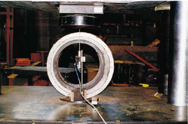
Ring-bending tests were conducted to verify the calcula-tion method of load sharing discussed above. Pipe ring spec-imens were prepared from an old cast iron pipe, an HDPE pipe, and a sliplined pipe with and without the HDPE liner pipe removed. Ring specimens of a nominal length of 153 mm were tested using the two-point loading method (Fig. 2). The detailed results of the laboratory tests can be found in Zhao et al. (2000).
The host pipe consisted of sections of a 350 mm, outside diameter (O.D.), cast iron pipe obtained from Québec City, Canada. These pipe sections were originally installed as part of the water distribution system in the city around 1865 and were removed from the ground in 1998. The cast iron pipe sections arrived with heavy rust, tubercles, and holes and
were cleaned by water blasting. There were noticeable graphitization areas on the cut surfaces of the pipe.
The liner pipe consisted of a 270 mm, O.D., HDPE pipe, manufactured from the PE 3408 material specification. Prior to ring-bending tests, a limited number of tensile and bend-ing tests were conducted usbend-ing bar specimens taken from the HDPE pipe to verify the short-term mechanical properties of the material (Zhao et al. 2000).
The grout ring was made from Type 20 cement and Type C fly ash mixed on site. The water/cementitious materials ratio was 0.38, and its tested compressive strength was 34.6 MPa at 34 days. The grout ring would have had a uni-form thickness of approximately 20 mm if the host pipe and liner pipe were concentric.
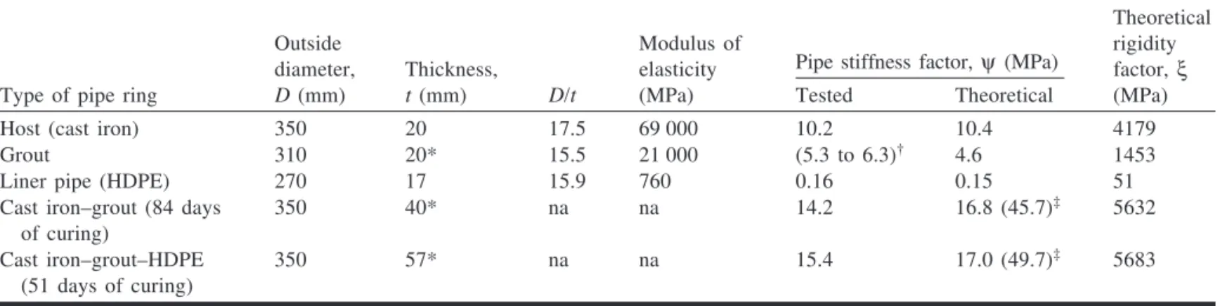
Table 1 shows the measured average dimensions and the modulus of elasticity of these pipe rings. The D/t ratios of the three rings ranged from 15.5 to 17.5. The modulus of elasticity of cast iron was taken from CIPRA (1952); the modulus of elasticity for HDPE was from Sclairpipe (1996) (for one-minute duration of load). The modulus of elasticity of the grout was calculated based on the measured mass den-sity of 1900 kg/m3 and the measured compressive strength
of 34.6 MPa (CSA 1984).
Pipe stiffness factors and external load sharing
The results from the two-point load tests can be used to verify the pipe stiffness factors and load sharing proportions calculated using eqs. [7] and [8]. Pipe stiffness factors can be determined from the ring-bending test (Howard 1981) as [10] ψ = 0.149W
y
∆
where W is the applied vertical load per unit length and ∆y is the measured vertical deflection. The theoretical and tested pipe stiffness factors, together with the theoretical ri-gidity factors are also shown in Table 1. The pipe stiffness Fig. 2. Testing of a cast iron–grout–HDPE pipe ring (three rings).
factors for the grout rings could not be determined by testing the rings alone because they would have been damaged dur-ing the process of removal from the host pipe. Instead, they were determined by subtracting the measured pipe stiffness of the cast iron ring from the measured pipe stiffness factors of the cast iron–grout specimen, and similarly from the cast iron–grout–HDPE specimen. For comparison, the theoretical pipe stiffness factors for fully bonded rings (the best case) were calculated using the section transformation method (McAlpine 1997) and the concentricity assumption. These values were 45.7 and 49.7 MPa for the cast iron–grout ring and cast iron–grout–HDPE ring, respectively (Table 1).
The theoretical pipe stiffness factors agreed well with the measured values, although the values for the grout rings were 15–37% higher than the theoretical value. This differ-ence could be attributed to increased modulus of the cementitious grout as a result of higher compressive strengths than the measured strength at 34 days. In addition, the tested pipe stiffness factor increased by 1.2 MPa with the inclusion of the HDPE ring, which was 6 times the theoreti-cal increase of 0.2 MPa. This can be attributed to the shear/friction strength at the ring interfaces. Rigidity factor of a sliplined pipe system in real applications is expected to lie between the best and the worst cases when the rings are concentric. The fact that the test results for the cast iron– grout ring and cast iron–grout–HDPE ring were 15.5% and 9.5% smaller than the theoretical worst case values, respec-tively, may be due to the effect of eccentricity of the rings in the sliplined pipe systems. Further discussions in this aspect are given later in this paper.
Rupture load — theoretical vs. test
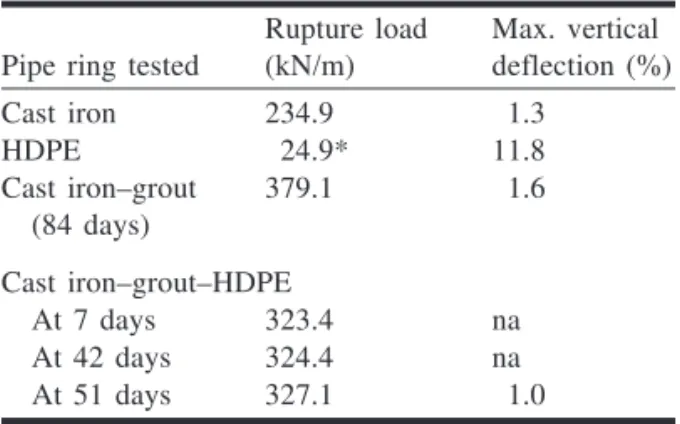
The load carrying capability of a sliplined pipe can be in-creased significantly as a result of the presence of the cementitious grout (Table 2). This is due to the fact that the external load is shared according to the pipe stiffness of the three pipe rings, as shown in eqs. [7] and [8]. The increase in load carrying capacity after rehabilitation is also reported by Osako et al. (1999). In their study, a box culvert was lined with a spiral wound liner and the cavity was grouted. One assumption used in the derivation of eqs. [1]–[9] was that all the pipe rings were concentric. This concentricity as-sumption rarely holds in the field installation of sliplining
rehabilitation. As a result, the grout ring thickness can vary from zero to the maximum gap, which equals the difference between the inside diameter of the host pipe and the outside diameter of the liner pipe. This variation can be represented by eccentricity e, which is defined as the distance between the centre points of the host and the liner pipe rings (eq. [11]).
[11] e=tmax−tmin
2
where tmax and tmin are the maximum and the minimum
grout ring thickness, respectively. When tmax= tmin, e = 0. In other words, there is no eccentricity, and the uniform thick-ness is 20 mm for the particular pipe specimens. The test data (Zhao et al. 2000) showed a decreasing trend of the rup-ture strength with the increase in eccentricity (Fig. 3), that is, with the increase in the differential between tmaxand tmin.
The decrease in rupture strength (R) was about 20% when the eccentricity increased from 5 to 16 mm. The minimum thicknesses (tmin) corresponding to this range of eccentricity were 13 and 5 mm. Note that the 20% decrease in rupture strength seems to be in line with the reduction of 15.5% and 9.5% in the tested pipe stiffness factors as compared to the theoretical values, as shown earlier in this paper. Further studies in this aspect may help establish reduction factors to count for the effect of eccentricity.
The linear trend line has the form of [12] R= −A B e = −A Bt −t
( ) max min
2
where R is the rupture load of the rehabilitated pipe; A is the rupture load when e = 0, which is the concentric case; and B is the slope of the trend line. The correlation coefficient, r2,
for the trend line is 0.2, which indicates that the correlation is weak for the available data set.
In addition to eccentricity, the direction of eccentricity in relation to the loading plane also affects the rupture load. The limited test data indicated that higher rupture loads were required when the direction of eccentricity was perpendicular to the loading plane than when it coincided with the loading plane. However, the effect of the direction of eccentricity, based on the test data, was not conclusive.
© 2001 NRC Canada
Zhao and Daigle 973
Type of pipe ring
Outside diameter, D (mm) Thickness, t (mm) D/t Modulus of elasticity (MPa)
Pipe stiffness factor,ψ (MPa)
Theoretical rigidity factor,ξ (MPa) Tested Theoretical
Host (cast iron) 350 20 17.5 69 000 10.2 10.4 4179
Grout 310 20* 15.5 21 000 (5.3 to 6.3)† 4.6 1453
Liner pipe (HDPE) 270 17 15.9 760 0.16 0.15 51
Cast iron–grout (84 days of curing)
350 40* na na 14.2 16.8 (45.7)‡ 5632
Cast iron–grout–HDPE (51 days of curing)
350 57* na na 15.4 17.0 (49.7)‡ 5683
*When the host and liner pipe were concentric.
†These values were obtained from the test values of the cast iron–grout and cast iron–grout–HDPE rings. ‡For fully bonded case (the best case).
The modulus of elasticity of the cementitious grout de-pends on the compressive strength and density of the cured grout (CSA 1984). Therefore, the ratio of rupture load (A) of the rehabilitated pipe (when e = 0) to that of the existing host pipe (R3) can be expressed as
[13] A R t t r r f E 3 2 3 3 3 2 3 2 2 3 1 = + 0.043ρ1.5
whereρ2 is the density of the grout, f2 is the compressive
strength of the grout at 28 days, and f3is the rupture strength of the host pipe material. In deriving eq. [13], the contribu-tion due to the liner pipe is insignificant and is neglected. The general equation that includes the liner pipe is
[14] R t t r r E E t t r r = + + 1 1 3 3 3 1 3 1 3 2 3 3 3 2 3 2 2 3 0.043ρ1.5 f E × − − R3 B t t 2 max min
The ratio expressed by eq. [13] can be used to calculate the increase in the load carrying capacity of the grouted
sliplined pipe compared to the host pipe prior to sliplining. Equation [13] shows that an increase in the grout thickness, density, or compressive strength will increase the load carry-ing capacity of the sliplined pipe.
Figure 4 is a plot of eq. [13] with the compressive strength of the grout as the horizontal axis. Values of other parameters correspond to those of the test pipes. In the case of the tested sliplined pipe, the ratio is 1.45 (i.e., 45% in-crease) based on f2 = 35 MPa. The average rupture load of the tested sliplined pipe specimens was 325 kN/m, and that of the cast iron pipe alone was 235 kN/m, giving an increase of 38%. Using eq. [13], one can obtain A/R3= 1.45, or 45%
increase for e = 0, compared to 38% with the eccentricity ef-fect. The average eccentricity for the data set is 10.5 mm. Using eq. [12], B = –6.3 (obtained from the trend line) and
e = 10.5 mm, the calculated rupture load is R = 332 kN/m,
which is 2.3% different from the average tested value of 325 kN/m. Therefore, eqs. [12] and [13] can be used to deter-mine the rupture load of a sliplined pipe-within-a-pipe sys-tem. The grout strength is one of the controllable parameters in a sliplined pipe system that can be varied to achieve a de-sired pipe strength to accommodate an increase in internal and (or) external loads (e.g., increased internal operating pressures, new road crossing over the pipe, etc.). The grout strength may also be limited by the requirement of high flowability of the grout in the annulus. Plasticizers may be added to the grout mix to increase the flowability, or closely spaced injection ports may be used to achieve a uniform placement of a high strength grout.
Example for estimating service life
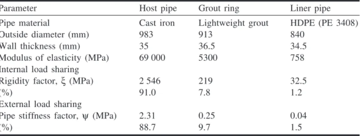
A practical example is shown below to illustrate how to estimate the service life of a sliplined watermain with annu-lus grouted with a lightweight grout mix. To achieve this goal, stresses in the rehabilitated pipe need to be determined for the applicable loads. The dimensions and material prop-erties of the three pipe rings used in this example are shown in Table 3. This example also demonstrates the effects of a Fig. 3. Effect of eccentricity on strength of sliplined pipe.
Pipe ring tested
Rupture load (kN/m) Max. vertical deflection (%) Cast iron 234.9 1.3 HDPE 24.9* 11.8 Cast iron–grout (84 days) 379.1 1.6 Cast iron–grout–HDPE At 7 days 323.4 na At 42 days 324.4 na At 51 days 327.1 1.0
*Maximum load on the load–deflection curve.
Table 2. Summary of average results on ring bend-ing test.
reduction in the wall thickness of the existing host pipe and the effects of the grout strength.
The lightweight cement grout has a density of 1630 kg/m3 and a 28-day compressive strength of 3.5 MPa, which gives a modulus of elasticity of 5290, using the CSA formulas (CSA 1984). The soil cover above the watermain is 1.5 m and has a unit weight of 18 kN/m3. Based on the dimensions and properties of the pipe materials, pipe stiffness factors and rigidity factors are calculated (Table 3).
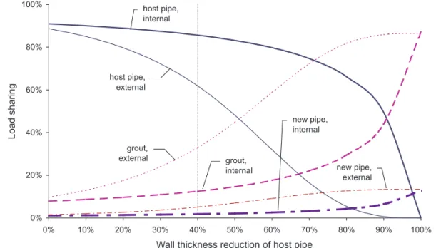
The wall thickness of a buried metal watermain reduces as natural deterioration (corrosion) takes place over time. A re-duction in the wall thickness of the existing host pipe plays an important role in distributing internal and external loads. This reduction in wall thickness is shown in Fig. 5 for both internal and external load sharing. The curves are produced by varying the thickness of the host pipe while holding all other parameters constant. The load sharing proportions of the host pipe decrease, as expected, with the reduction in its wall thickness, but the decrease is more rapid for the exter-nal loads than for the interexter-nal loads. For example, for a 40% wall thickness reduction, the external load sharing propor-tion of the cast iron pipe reduces from 89% to 62%, whereas
the internal load sharing proportion reduces from 91% to 86%. The liner pipe has only a small increase in load shar-ing for both internal and external loads. It is important to note that the cement-based grout has a low tensile strength and once this strength is reached, it will crack and have no capacity to share internal tensile loads. The sharing of exter-nal loads by the cracked grout ring requires more study.
The effect of the grout strength on load sharing was ob-tained by varying the compressive strength while all other parameters remained constant (Fig. 6). An increase in the grout strength from 5 to 25 MPa led to an increase from 15% to 29% of the load sharing proportion of the grout ring for internal load increases and an increase from 19% to 34% for the load sharing proportion for external loads.
Service life of a sliplined watermain
Stress, fatigue loading, and temperature are the main fac-tors that affect the service life of an HDPE pipe (Bowman 1990; PPI 1993, 1997, 1998; ASTM 1992; Driscopipe 1996). In general, the lower the stress, the longer the service life. Bowman (1990) examined the fatigue strength of poly-ethylene and PVC water pipe systems. Both stress level and
© 2001 NRC Canada
Zhao and Daigle 975
Fig. 4. Rupture load of the rehabilitated pipe vs. grout strength.
Parameter Host pipe Grout ring Liner pipe Pipe material Cast iron Lightweight grout HDPE (PE 3408)
Outside diameter (mm) 983 913 840
Wall thickness (mm) 35 36.5 34.5
Modulus of elasticity (MPa) 69 000 5300 758 Internal load sharing
Rigidity factor,ξ(MPa) 2 546 219 32.5
(%) 91.0 7.8 1.2
External load sharing
Pipe stiffness factor,ψ (MPa) 2.31 0.25 0.04
(%) 88.7 9.7 1.5
its cyclic frequency affect the time to failure of HDPE pipe (Barker and Bevis 1983) as well as metal pipe. In addition, the average stress, referred to as creep stress, plays an im-portant role in the service life of the pipe.
The service life of an HDPE pipe is projected to be more than 50 years for a stress level of 5520 kPa (800 psi) (Driscopipe 1996). Under combined internal and external loads, the maximum stress in the HDPE pipe is calculated to be less than 200 kPa, or less than 2% of its yield strength of 11 000 kPa. Therefore, the inserted HDPE pipe will act as a watertight liner until the host pipe fails. Furthermore, the foregoing analysis shows that a grouted, existing cast iron pipe will be subjected to lower stress than original, which translates to a higher load carrying capacity (eq. [13]). Un-der the same orUn-der of applied internal and external loads as those before sliplining, lower stresses in the host cast iron
pipe result in a longer life, thus providing longer protection to the inserted HDPE pipe. As a result, the service life of the watermain is expected to be longer than that assumed in the design for rehabilitation.
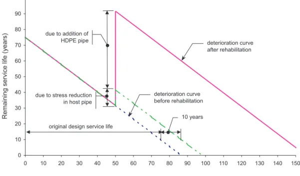
In the following example, a linear deterioration (or any nonlinear) curve for the cast iron pipe with a design service life of 75 years was assumed. Further, sliplining was as-sumed to be carried out 50 years after the original construc-tion. The deterioration curves for the original and rehabilitated watermain are shown schematically in Fig. 7. Without sliplining rehabilitation, the existing pipe would have 10 years of remaining life when it reached its design service life. However, after sliplining the watermain pipe gained 50 years of service life from the inserted HDPE pipe (Driscopipe 1996), in addition to the number of years gained as a result of the reduction in the stress level in the host cast Fig. 5. Effect of host pipe wall thickness on load sharing.
iron pipe. This additional life can be estimated based on ac-tual stress reduction in the pipe wall when imposed loads are defined, but for this example is assumed to be 10 years. The remaining service life is then increased to about 90 years.
The deterioration curves shown in Fig. 7 are for illustra-tion purposes only. Actual deterioraillustra-tion curves of cast iron pipe and sliplined pipe, when available, should be used.
What happens when the host pipe fails? The HDPE pipe is then expected to take the full internal and external loads. The grout ring may have failed owing to hoop tensile stresses but may still provide protection against pinching and scratching of the HDPE pipe. The failed host pipe and the grout ring may even provide some degree of load carrying capacity because of the lateral support from the soils. How-ever, more research is required to investigate the modes of failure of host pipe and their effect on the liner pipe. Fur-thermore, the response of the sliplined multi-ring system was evaluated using the two-point loading method in this pa-per, which may not correctly relate to the response of the pipe embedded in the soils by the traditional bedding factor approach. Further studies could be undertaken to evaluate the relevance of two-point loading to characterize the strength of the repaired pipeline under earth loads and in embedded soils.
Conclusions
A practical method for determining load sharing in a grouted sliplined watermain is presented and verified by lab-oratory tests. Use of the method is demonstrated by a practi-cal example. The closed-form equations derived based on the thin-walled theory provide reasonable quantitative esti-mates on load sharing among the sliplined pipe rings. Al-though the method is developed based on a pressurized watermain, it can be used to assess the load carrying capac-ity of non-pressurized pipes such as sewers, in which case
the thrust and shear must be taken into account. The follow-ing conclusions can be made based on the analysis and the laboratory test results.
• There is little bond strength at the interfaces between the grout and the HDPE pipe, and between the grout and the cast iron pipe in a grouted sliplined watermain. The reha-bilitated pipe is a pipe-within-a-pipe system, and the rings interact with each other independently.
• The load carrying capacity of a watermain pipe increases substantially after it is sliplined. The grout ring acts as a structural element when its tensile stresses are below the tensile strength. The eccentricity between the host pipe and the liner pipe has an impact on the rupture load of the sliplined pipe. The rupture load decreases with the in-crease in eccentricity. A general equation has been derived that can be used to calculate the rupture load (R) of the re-habilitated pipe. The grouted sliplining method can be used to strengthen an existing pipe.
• The direction of eccentricity affects the rupture load of the sliplined pipe. The rupture load is higher when the direc-tion of eccentricity is perpendicular to the loading plane than when it coincides with the loading plane.
• Load sharing capability of the rings depends on their ri-gidity factors for internal loads, and on their pipe stiffness factors for external loads. These two factors are related by the ratio of mean diameter to mean wall thickness. • The load sharing capability of the host pipe decreases
more rapidly for the external load than for the internal loads, as its wall thickness decreases.
• The load sharing capability of the grout ring increases while the load sharing proportion of the host pipe de-creases as grout strength inde-creases. The grout strength can be controlled to meet a specific design objective. • Sliplining increases the remaining service life of the
watermain pipe. Furthermore, reducing the stress level in the host pipe can lead to an increase in service life.
© 2001 NRC Canada
Zhao and Daigle 977
Acknowledgments
This paper is a result of a research project jointly funded by the City of Ottawa (formerly the Regional Municipality of Ottawa-Carleton or RMOC) and the National Research Council Canada (NRCC). Assistance from Mr. Michael Willmets of RMOC and Mr. Derek Potvin of Robinson Con-sultants during the project is gratefully acknowledged. The critical review and comments from Dr. B.B. Rajani of NRCC during the preparation of this paper are appreciated.
References
Aarseth, L.I., and Hovde, P.J. 1999. A stochastic approach to the factor method for estimating service life. Proceedings of the 8th Durability of Building Materials and Components Conference, Vancouver, B.C., May 30 – June 3. Edited by M.A. Lacasse and D.J. Vanier. pp. 1247–1256.
ASCE. 1984. Structural plastics design manual. ASCE manuals and reports on engineering practice No. 63. American Society of Civil Engineers, New York, N.Y.
ASTM. 1992. Standard test method for obtaining hydrostatic de-sign basis for thermoplastic pipe materials. Standard D2837-92, American Society for Testing and Materials, Philadelphia, Pa. ASTM. 1996. Standard practice for installation of poly(vinyl
chlo-ride)(pvc) profile strip liner and cementitious grout for rehabili-tation of existing man-entry sewers and conduits. Standard F1698-96, American Society for Testing and Materials, Phila-delphia, Pa.
Barker, M.B., and Bevis, J.B. 1983. The performance and causes of failure of polyethylene pipes subjected to constant and fluctuat-ing internal pressure loadfluctuat-ings. Journal of Materials Science, 18: 1095–1118.
Beer, F.P., and Johnston, E.R. 1985. Mechanics of materials. McGraw-Hill Ryerson Ltd., Toronto, Ont.
Bowman, J.A. 1990. The fatigue response of polyvinyl chloride and polyethylene pipe systems. Buried Plastic Pipe Technology, ASTM STP 1093, pp. 101–121.
CIPRA. 1952. Handbook of cast iron pipe for water, gas, sewerage and industrial service. 2nd ed. Cast Iron Pipe Research Associa-tion, Chicago, Ill.
CSA. 1984. Design of concrete structures for buildings. Standard CAN A-23.3-M84, Canadian Standards Association, Rexdale, Ont.
Driscopipe. 1996. Engineering characteristics. Phillips Driscopipe, Richardson, Tex.
Flourentzou, F., Brandt, E., and Wetzel, C. 1999. MEDIC — a method for predicting residual service life and refurbishment in-vestment budgets. Proceedings of the 8th Durability of Building Materials and Components Conference, Vancouver, B.C., May 30 – June 3. Edited by M.A. Lacasse and D.J. Vanier. pp. 1280– 1288.
Hickle, J.E., and Glasgow, K.L. 1997. Design and installation of large diameter slipliner pipe in Lakeland, Florida. Proceedings of Trenchless Pipeline Projects: Practical Applications, Boston, Mass., June 8–11, pp. 382–389.
Howard, A.K. 1981. The USBR equation for predicting flexible pipe deflection. Proceedings of the International Conference on Under-ground Plastic Pipe, New Orleans, La., March 30 – April 1. Edited by B.J. Schrock. pp. 37–55.
Kleiner, Y. 2000. Decision support framework for rehabilitation and scheduling inspection of large sewers. Client Report B-5109.1, Institute for Research in Construction, National Re-search Council Canada, Ottawa, Ont.
McAlpine, G. 1997. Structural rehabilitation of rigid pipes. Pro-ceedings of Trenchless Pipeline Projects: Practical Applications, June 8–11, Boston, Mass., pp. 458–465.
Moser, A.P. 1990. Buried pipe design. McGraw-Hill, Inc., New York, N.Y.
Osako, K., Takahashi, Y., Kitahaasi, N., Akimoto, E., Nakatsui, K., and Nakano, M. 1999. Renovation technology and evaluation of load carrying capacity for sewage pipe renewal method. Confer-ence on Infrastructure Regeneration and Rehabilitation, Im-proving the Quality of Life Through Better Construction, A Vision for the Next Millennium, Sheffield, U.K., June 28 – July 2, pp. 843–852.
PPI. 1973. Weatherability of thermoplastic piping. Technical Re-port TR-18/73, Plastics Pipe Institute, Washington, D.C. PPI. 1993. Engineering properties of polyethylene. Plastics Pipe
Institute, Washington, D.C.
PPI. 1997. Hydrostatic design bases and maximum recommended hy-drostatic design stresses for thermoplastic piping materials. Techni-cal Report TR-4/97b, Plastics Pipe Institute, Washington, D.C. PPI. 1998. HDB policies. Technical Report TR-3, Plastics Pipe
In-stitute, Washington, D.C.
Sclairpipe. 1996. High density polyethylene pipe systems design. KWH Pipe, Mississauga, Ont.
WRc. 1994. Sewerage rehabilitation manual. 3rd ed. Water Re-search Centre, Wiltshire, U.K.
Zhao, J.Q., Daigle, L., and Boudreau, S. 2000. Performance assess-ment of HDPE sliplining of Gloucester street watermain — final report. Client Report B-5105.2, Institute for Research in Con-struction, National Research Council Canada, Ottawa, Ont.
List of symbols
A rupture load when eccentricity e = 0 B slope of the trend line
D mean diameter of a pipe ring
E modulus of elasticity of a pipe material
e eccentricity between the host pipe and the liner pipe f2 compressive strength of the grout at 28 days f3 rupture strength of the host pipe material
I section modulus of pipe wall pint internal pressure
R rupture load of the rehabilitated pipe r mean radius of pipe ring
t wall thickness
tmax maximum grout ring thickness tmin minimum grout ring thickness
W applied vertical load per unit length Wsoil load due to soil
Wtraf load due to traffic
∆y measured vertical deflection
ξ rigidity factor (= Et/D)
ρ density of pipe material
σ stress in pipe wall
ψ pipe stiffness factor (= EI/r3)
Subscripts
1 liner pipe ring 2 grout ring 3 host pipe ring int internal ext external