HAL Id: hal-00569612
https://hal.archives-ouvertes.fr/hal-00569612
Submitted on 25 Feb 2011
HAL is a multi-disciplinary open access archive for the deposit and dissemination of sci-entific research documents, whether they are pub-lished or not. The documents may come from teaching and research institutions in France or abroad, or from public or private research centers.
L’archive ouverte pluridisciplinaire HAL, est destinée au dépôt et à la diffusion de documents scientifiques de niveau recherche, publiés ou non, émanant des établissements d’enseignement et de recherche français ou étrangers, des laboratoires publics ou privés.
by spin-transfer torque
W Guo, Guillaune Prenat, V Javerliac, M El Baraji, N de Mestier, C
Baraduc, B Diény
To cite this version:
W Guo, Guillaune Prenat, V Javerliac, M El Baraji, N de Mestier, et al.. SPICE modelling of magnetic tunnel junctions written by spin-transfer torque. Journal of Physics D: Applied Physics, IOP Publishing, 2010, 43 (21), pp.215001. �10.1088/0022-3727/43/21/215001�. �hal-00569612�
written by Spin Transfer Torque
W Guo1 , G Prenat1 , V Javerliac2 , M El Baraji2 , N de Mestier1 , C Baraduc1and B Di´eny1
1SPINTEC, UMR(8191), INAC, CEA/CNRS/UJF, 17 Av. des Martyrs, 38054
Grenoble Cedex 9, France
2CROCUS Technology, 5 Place Robert Schuman, 38025 Grenoble, France
E-mail: wei.guo@cea.fr
Abstract. Spintronics aims at extending the possibility of conventional electronics by using not only the charge of the electron, but also its spin. The resulting spintronic devices, combining the front-end CMOS technology of electronics with a magnetic back-end technology, employ Magnetic Tunnel Junctions (MTJs) as core elements. With the intent of simulating a circuit without fabricating it first, a reliable MTJ electrical model which is applicable to the standard SPICE (Simulation Program with Integrated Circuit Emphasis) simulator is required. Since such a model was lacking so far, we present an accurate MTJ SPICE model whose magnetic state is written by using the Spin-Transfer Torque (STT) effect. This model has been developed in C language and validated on the Cadence Virtuoso Platform with Spectre simulator. Its operation is similar to those of the standard BSIM (Berkeley Short-channel IGFET Model) SPICE model of the MOS transistor and fully compatible with the SPICE electrical simulator. In order to illustrate the model performance, we studied the tunneling conductance and STT-driven magnetization dynamics by comparing our simulation results with theoretical macrospin calculations and results found in the literature.
1. Introduction
Tremendous interest in investigating spintronic devices has been triggered in both fundamental research and industrial applications since 1988. For instance, Magnetic Random Access Memories (MRAMs) [1] are considered as one of the most promising candidates for universal memory since they combine non-volatility, speed, high-density, low-power consumption, hardness to radiations and endurance. MRAMs comprise Magnetic Tunnel Junctions (MTJs) as storage elements. Beyond MRAMs, some recent investigations of MTJs have shown their potential applications in magnetic logic circuits [2, 3] and RF oscillators [4] as well. A novel writing mechanism of the MTJs, which relies on the so-called Spin-Transfer Torque (STT) effect, has attracted much attention recently because it brings several advantages in comparison with conventional field induced writing approach, in particular lower power-consumption, better scalability and reduction of data disturbance. The Complementary Metal Oxide Semiconductor (CMOS) technology is steadily improving. However, it is generally admitted that within a few years, it will meet some physical limits. Hybrid technology such as the CMOS/Magnetic technology may allow to circumvent some of these limits and in addition provide power consumption reduction as well as new functionalities.
Electronic circuit simulation plays a very important role in modern Integrated Circuit (IC) development process. The first powerful simulation tool is SPICE (Simulation Program with Integrated Circuit Emphasis), which was originally introduced in early 1970s by the University of California, Berkeley [5]. It was then adopted by the IC industry and served as the basis for standard industrial circuit simulators (SPECTRE for CADENCE, Eldo for Mentor Graphics and HSPICE for Synopsys). SPICE allows the accurate simulation of a complicated circuit without having to breadboard a prototype, test it, and redesign it based on the testing results. The only factor that determines the accuracy and the reliability of the IC simulation data with respect to its practical testing results is the quality of the electrical model of the circuit element. Thus, one essential requirement for designing hybrid CMOS/Magnetic circuits is an efficient MTJ SPICE model that is capable of accurately replicating its physical behaviour in an electrical representation.
Any conventional circuit elements, such as resistor, capacitor or MOS transistor, can be considered as the so-called ”black box” with certain nodes in the circuit description. A circuit is then described as a collection of all these ”black boxes” interconnected with each other. Voltages at any nodes in the circuit are calculated by using the Nodal Analysis technique based on Kirchhoff’s current law (KCL). In SPICE, a circuit element with n nodes can be represented by n×n resistance matrix or capacitance matrix. For example, a resistor has two nodes and it can be described by the following matrix
" 1 R − 1 R −1 R 1 R # (1)
currents. Regarding the MTJ, due to its unique characteristic, it cannot be modeled as other conventional circuit elements. The current that can pass through the junction is closely related to its magnetization state and working temperature. Its physical equations are not compatible with any existing equivalent RC components in SPICE. Therefore, much complex work has been carried out to reformulate its physical equations. The MTJ matrix entries are very complex mathematical functions derived from those reformulated equations. The presented MTJ model includes 9 nodes, in which 4 external nodes for real circuit connections and especially 5 internal virtual nodes for constructing virtual equivalent circuits to describe its electrical, magnetic and thermal behaviours. This causes a large 9×9 matrix is used to represent the MTJ in SPICE. In order to follow the usual SPICE representation for the virtual circuits, the three components of the magnetization (mx, my and mz) and the temperature are treated as virtual voltages
in the simulation. The presented SPICE-like MTJ model is compatible with SPECTRE simulator.
This model differs from the previous ones [6, 7, 8] in the following points. Firstly, it can reproduce both the static and dynamic behaviours of the magnetization. Secondly, because the dependence of device performance on thermal effect becomes predominant when MTJ size reaches nanometric scale, this model takes into account the influence of the varying temperature on the material properties. Thirdly, the dynamic evolution of the junction temperature is included as well.
In this paper, a description of the STT-based MTJ is first presented. Next, we discuss the related physical equations and the implementation of the model. Some illustrative simulation results are then presented. The variation of the MTJ tunneling conductance as a function of its magnetic state, bias voltage and temperature is discussed. We also study the STT-driven magnetization dynamics by using this model and compare it with previously reported results.
2. Magnetic Tunnel Junctions
An MTJ is usually composed of two ferromagnetic (FM) layers separated by an insulating barrier. The magnetization of one FM layer is pinned (hard layer), and it acts as a reference layer. The magnetization of the other FM layer (soft layer) can be switched between two stable states, either parallel (P) or antiparallel (AP) with respect to the reference layer. Electrons can tunnel through the thin barrier (a few nanometers or less) when a bias voltage is applied between the two electrodes of the device. The MTJ resistance is low (or high) for P (or AP) magnetization configuration. These two configurations can be used to represent logical 0 and 1, respectively (figure 1). This resistance variation behaviour was first observed and explained by Julli`ere [9].
Tunneling Magnetoresistance Ratio (TMR) describes the ratio between the two resistance values as expressed in equation (2).
Figure 1. Schematic representation of the resistance variation in an MTJ. The transitions between resistance values are hysteretic.
T M R= RAP − RP RP
(2)
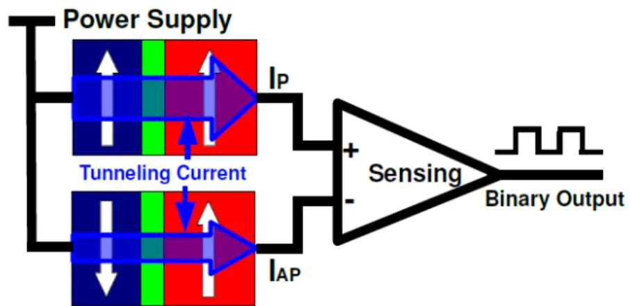
Large TMR up to several hundred percent can be obtained with MgO-based tunnel barrier at room temperature [10]. This large variation of device resistance can result in high output voltage swing (hundred mV), which is significant for MTJ reading because it ensures small and stable CMOS sensing circuit and enhances the accuracy of read out signal. Two MTJs, which have opposite magnetic states, are usually used to store one data bit. The reading mechanism relies upon measuring the effective resistance difference between the two MTJs. It can be achieved by applying a voltage and sensing the currents (figure 2).
Figure 2. MTJ twin cell reading mechanism. The tunneling current associated with the P state MTJ (IP) is larger than current through the AP state MTJ (IAP). The
difference between these two currents is sensed and compared in the CMOS sensing circuit to determine the value of the stored data.
Conventional writing approaches of MTJ rely on the Oersted applied field generated by a remote current pulse in the field line [11]. A novel writing method has been proposed more recently following Slonczewski [12] and Berger’s [13] predictions of the STT effect. In this approach, the magnetization of the soft layer can be reversed by
Figure 3. MTJ written by Spin-Transfer Torque effect. Current flows from the top electrode to the bottom electrode favors the P state, while the opposite injected current favors the AP state.
only sending a high density spin-polarized current through the junction. The injected current direction determines whether the final state of the magnetization is P or AP (figure 3). The switching current is significantly reduced thus providing a favorable downsize scalability and low writing power. STT writing provides a local means of magnetization manipulation. The external magnetic field is no longer needed, high integration density and weak data disturbance can be therefore achieved. On the other hand, if a magnetic field is applied in conjunction with the spin-polarized current with appropriate direction, steady precession of magnetic state can be obtained. This can be quite interesting for the design of RF oscillators.
3. SPICE modeling of STT-Based MTJ
The purpose of a SPICE model is to obtain a simple, fast and accurate electrical representation of the physical behaviour of a device. The modeling of the STT-based MTJ starts with the analysis of model equations along with some approximations. A number of associated parameters are then fed into these equations. The simulator represents the established equations as equivalent circuit elements.
3.1. Macrospin approximation
The development of this model is under a macrospin (single domain) approximation. Since the size of the junction has reached nanometric scale, it is reasonable to assume that the magnetization behaves as a single macroscopic magnetic moment in the ferromagnetic material. This assumption considerably simplifies the mathematical analysis and can give as accurate predictions as with micromagnetic analysis for typically sub-100 nm size devices.
3.2. MTJ tunneling conductance
Following the first TMR model by Julli`ere [9] and Slonczewski’s further work [14], the tunneling conductance is a function of the angle between the magnetizations of the two FM layers. Furthermore, the bias-dependent conductance of the device at 0 K can be derived in the framework of Brinkman’s model [15] and Simmons’ model [16].
In addition, the electrical and magnetic characteristics of the MTJ strongly depend on its temperature variation which is due to the self-heating of the junction by Joule effect. This temperature variation must be carefully considered in order to perform more accurate simulations. Therefore, the temperature dependence of the tunneling conductance is taken into account based on Stratton’s model [17].
As previously mentioned, the device conductance depends on the angle (θ) between the magnetizations of the two FM layers, the bias voltage (V ) applied across the device and its temperature (T ). The resulting total tunneling conductance can then be written as shown in equation (3). G(θ, T, V ) = G0[1 + P1(T )P2(T ) cos θ] λT sin(λT ) (1 − βV + δV2 ) + Gsi(T ) (3)
where λ, β and δ are material-dependent constants, G0 is the conductance in
parallel magnetic configuration at 0 V and 0 K, Pi(T ) (i=1, 2) are the
temperature-dependent polarization factors of the two FM layers as defined in [18], and Gsi(T ) is
the spin-independent conductance which describes a non-magnetic contribution to the conductance versus temperature variation [19].
3.3. Spin-transfer driven magnetization dynamics
The magnetization dynamics of the soft layer is described by the Landau-Lifshitz-Gilbert equation [20, 21] with the addition of a bias-dependent in-plane STT term [22] as shown in equation (4). d ~m dt = − γ0 1 + α2m~ × ~Hef f − α γ0 1 + α2m~ × ( ~m× ~Hef f) − ajV ~m× ( ~m× ~p) (4)
where ~m and ~p are the unit vectors along the magnetizations of the soft and hard layers, respectively. ~Hef f is the effective field which consists of the magnetocrystalline
anisotropy field, the demagnetizing field and the external field, α is the Gilbert damping constant, γ0 is the gyromagnetic ratio, aj is the prefactor of the in-plane STT term, V
is the bias voltage.
We can notice from equation (4) that the soft layer magnetization dynamics depends on the effective field and bias voltage. The first term in equation (4) describes the elliptical precession of the magnetization around the applied magnetic field. The second
term in equation (4) is the Gilbert damping torque which forces the magnetization to relax towards the effective field. When a bias voltage is applied across the MTJ, a resulting current then flows through the junction. This current causes a torque (STT) that can affect the local magnetization. The last term in equation (4) describes the in-plane STT effect which may enhance or reduce the damping torque according to the direction of the injected current. For a sufficiently high current, the spin torque can compensate or even exceeds the natural damping torque, which leads to magnetic oscillations or complete magnetization reversal.
3.4. Heat diffusion
The junction temperature increases when a current is injected. This is due to the Joule heating associated with the relaxation to the Fermi energy of the hot electrons tunneling through the barrier. In order to evaluate the time-dependent temperature evolution of the junction, the heat conduction equation with source term is introduced in this model as defined in equation (5). Cρ∂T ∂τ = k ∂2 T ∂x2 + RA ∗ J 2 δ(x) (5)
where C is the specific heat, ρ is the volume density of the material, k is the thermal conductivity, RA is the resistance×area product of the MTJ, J is the current density, δ is the Dirac distribution, the barrier is being located at x = 0, time τ and space coordinate x are independent variables.
3.5. SPICE modeling implementation
This STT-based MTJ model has been implemented in C-language, compiled with the compiled-model interface (CMI) provided by Cadence Design Systems. This model supports 9 nodes, including 4 external nodes and 5 internal nodes. The MTJ simulation cell view is shown in figure 4. Two inputs BL0 and BL1 represent the two electrodes of the junction which is modeled by its tunneling conductance and capacitance. One field line, with two nodes FL0 and FL1, is used for the analysis of magnetization dynamics in presence of external field. In order to ease the understanding of the device behaviour, internal nodes such as device temperature (th) and magnetic state (my) can also be monitored and plotted. This model includes 38 parameters, among which the geometrical parameters such as the shape, the size and the initial magnetic state of the MTJ are user-defined to perform the intended simulations. In contrast, the other physical and technological parameters are defined in a corner file and cannot be modified by users since they are provided by the manufacturer.
4. Results and Discussion
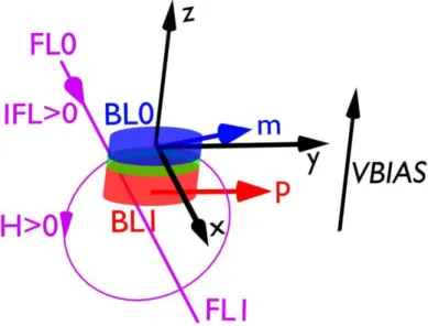
The following conventions are used in the discussion of simulation results (figure 5): (1) The magnetization of the hard layer and the initial magnetization of the soft layer are
Figure 4. Simulation view of an MTJ. The current source sends a bi-directional current IFL that flows in the field line to generate an external magnetic field on the MTJ soft layer. The voltage source VBIAS provides either positive-bias or negative-bias across the MTJ for the simulation of STT effect.
Figure 5. Model conventions for simulation and discussion.
assumed to be along the y-axis, implying P initial state. (2) Negative bias favors the AP state (low conductance). (3) The external magnetic field generated by a positive field line current (flows from FL0 to FL1) favors the AP state. A set of experimental-based parameter is fed into the model for simulations. The diameter of the circular shape MTJ is 100 nm. The thickness of the soft layer is 1 nm. Without external field, the bias voltage required to cause the switching is ±0.39 V. The corresponding total current and current density required to switch the magnetization from P (AP) to AP (P) at 10 ns width of voltage pulse are -321.85 µA and -4.1 MA/cm2
(IAP −P
Figure 6. Transient simulation results. (a) Negative bias applied across the MTJ. (b) Temperature evolution of the MTJ. (c) Corresponding current through the MTJ, which is influenced by magnetic state, bias voltage and temperature.
µA and JAP −P
c =2.01 MA/cm 2
), respectively. In the case of field induced magnetization switching (without STT effect), the field line current required to generate an external field that can switch the magnetization is ±7.8 mA (distance from field line to soft layer is 350 nm).
4.1. Tunneling conductance variation
When a sufficient negative bias voltage (≈-400 mV) is applied between the two electrodes of the junction (figure 6(a)), its temperature begins increasing (figure 6(b)) and the soft layer magnetization switches from P to AP. The switching behaviour can be detected by plotting the corresponding current through the MTJ (figure 6(c)). Since the initial conductance is high (P state), the resulting current before switching is also high (≈-340 µA). In contrast, a lower current (≈-160 µA) flows through the junction after switching because the device conductance changes to low (AP state) and as a result, the device temperature decreases.
We notice that oscillations of increasing amplitude appear just before the switching. This is a manifestation of the STT effect before the switching when the influences of the STT and initial effective field are in competition. In addition, we can observe that the resulting current is not constant (not a straight line) in figure 6(c). It keeps increasing slightly with increasing temperature (zone marked with 1). In contrast, when the temperature drops, the current decreases accordingly (zone marked with 2). These trends reflect the increase of tunneling conductance with increasing temperature.
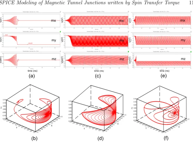
Figure 7. STT-driven magnetization dynamics without external field. (a) Damped oscillations of magnetization, Vbias=-0.25 V. (b) Magnetic trajectory in the regime of damped oscillations. (c) In-Plane Precession (IPP) simulation result, Vbias=-0.35 V. (d) IPP magnetic trajectory. (e) Simulation result of magnetization switching, Vbias=-0.43 V. (f) Magnetic trajectory of switching.
states, corresponding to low and high resistance states, associated with logical 0 and 1). However, as previously mentioned, the magnetization dynamics induced by STT can also be very interesting for RF applications in particular frequency tuneable RF oscillators. Therefore, we studied the STT-driven magnetization dynamics with external magnetic field by comparing our simulation results with [23, 24] and found good agreement.
4.2. STT-driven magnetization dynamics in absence of external field
We first consider the case without external field. Three different behaviours can be observed as shown in figure 7. Top figures in figure 7 are Spectre simulation results of 3 internal nodes which represent the projections of the soft layer magnetization onto the 3 coordinate axes. We extracted the simulation data and plotted the corresponding 3-D magnetic trajectories as shown in bottom figures. When a negative bias voltage less than a first critical value |Vc1| (0.32 V) is applied across the junction, the magnetization leaves its original position and begins to oscillate with relatively small amplitude due to the STT effect. Since the spin torque is not strong enough to compensate the damping torque, the magnetization oscillates with decreasing amplitude and gradually goes back
Figure 8. STT-driven magnetization dynamics with external field. (a) Simulation results of magnetization switching, Vbias=-0.5 V, Ifl=-3.5 mA. (b) Magnetic trajectory of switching. (c) IPP simulation result, Vbias=-0.5 V, Ifl=-10 mA. (d) IPP magnetic trajectory. (e) Out-of-Plane Precession (OPP) simulation result, Vbias=-0.8 V, Ifl=-10 mA. (f) OPP magnetic trajectory.
to its original position (figure 7(a) and (b)).
We further increase the bias voltage beyond |Vc1| but less than a second critical value |Vc2| (0.39 V). The initial stable state (P) becomes unstable and an oscillation over a finite time window can be observed. The oscillation then enters a steady state along an approximately elliptical trajectory (figure 7(c) and (d)). We notice that the precession is symmetrically (or nearly so) around an axis that lies in the x-y plane. Thus, this dynamic state is called in-plane precession (IPP).
When the bias voltage exceeds |Vc2|, the previous steady precession angle increases until the magnetization penetrates in the opposite hemisphere with respect to the initial state. At this point, the magnetization switching occurs (figure 7(e) and (f)).
4.3. STT-driven magnetization dynamics in presence of external field
When an external field is further introduced, three different magnetic behaviours are obtained as shown in figure 8. We first apply a bias voltage which is higher than |Vc2| but less than 2|Vc1| across the junction. In addition, an external field is applied along the easy axis of magnetization of modulus lower than the soft layer coercive field. In
other words, the applied field produced by the field line current is not sufficient to cause field induced magnetization switching. In our case, the field line current is less than |Ifc| = 7.8 mA. The applied field (generated by negative field line current) favors the P state. However, the resulting spin torque, which favors the AP state, is dominant in the competition with this applied field. As a result, the magnetization switches from P to AP (figure 8(a) and (b)).
Then we increase the field line current over |Ifc| and keep the bias voltage at the same value as previously applied. IPP of the magnetization can be observed (figure 8(c) and (d)). We notice from figure 8(d) that the magnetic trajectory penetrates in the negative y hemisphere, which is different from figure 7(d). This is due to the strong STT effect and its influence on the magnetic precession.
When a bias voltage higher than 2|Vc1| is applied across the junction and keeps the field current higher than |Ifc|, the precession axis of the soft layer magnetization may leave the x-y plane, resulting in a large out-of-plane (OPP) precession (figure 8(e) and (f)).
4.4. Phase diagram
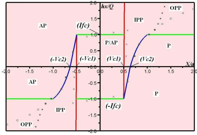
A number of simulations were performed with different bias voltages and field line currents to determine the threshold values from which the soft layer magnetization transits from one state to another. We transformed these values to corresponding scalar values as defined in [23, 24] and then normalized for comparison purpose. The resulting phase diagram of STT-driven magnetization dynamics is obtained as shown in figure 9. Five regions can be distinguished: one region where both initial states are stable (P/AP), two regions where either P or AP is stable and two regions where magnetic precessions occur (IPP, OPP).
We note from the phase diagram that the first critical bias |Vc1| describes only the onset of the precessional state from the central bistable region, while the second critical bias |Vc2| is distinctly different and larger than |Vc1|. When the field line current exceeds |Ifc|, a field larger than the coercive field is generated, the magnetic state evolves towards the IPP. For even larger bias voltages, OPP takes place. The model also shows that the precession is expected to be the precursor state to both the P to AP and AP to P transitions, which has been confirmed by experiments [25]. The resulting phase diagram is in good agreement with previously calculated macrospin phase diagram [23, 24].
5. Conclusion
The presented accurate STT-based MTJ SPICE model is significant for the design and the optimization of complex hybrid CMOS/Magnetic circuits with standard electrical simulator. It is the first STT-based MTJ SPICE model which includes the electrical and physical characteristics, the time-dependent evolution of device temperature and the
Figure 9. Normalized phase diagram as a function of X/a and hx/Q, two
dimensionless quantities proportional to bias voltage and applied field, respectively. Colored lines are theoretical phase boundaries. While cross, star and square marks are obtained from Spectre simulations to determine the phase boundaries of the stable states, IPP and OPP. |Vc1|=0.32 V,|Vc2|=0.39 V, |Ifc|=7.8 mA.
temperature-dependent variations of model parameters. It is compatible with Spectre simulator and can be easily migrated to other platforms.
Regarding further improvement of this model, we intend to introduce a second weaker component of the STT, the out-of-plane torque term for MTJ stacks. The stochastic effects induced by the thermal fluctuations of magnetization will be also taken into account and their influences on electrical noise will be modeled. In addition, this model will be continuously updated based on the progress in physical understanding of STT effect and the improvement of related technologies.
Acknowledgments
This work is funded by the National Agency of Research under Grant ANR-06-NANO-066 (CILOMAG).
References
[1] Ricardo C. Sousa and I. Lucian Prejbeanu 2005 Comptes Rendus Physique 6 1013
[2] W. Zhao, E. Belhaire, V. Javerliac, C. Chappert, B. Dieny 2006 IEEE International Conference on Integrated Circuit Design and Technology p 1
[3] Shoun Matsunaga, Jun Hayakawa, Shoji Ikeda, Katsuya Miura, Haruhiro Hasegawa, Tetsuo Endoh, Hideo Ohno, Takahiro Hanyu 2008 Applied Physics Express 1 091301
[4] S.I. Kiselev, J.C. Sankey, I.N. Krivorotov, N.C. Emley, R.J. Schoelkopf, R.A. Buhrman, D.C. Ralph 2003 Nature 425 380
[5] L. Nagel and D. Pederson 1973 Berkeley, University of California, Electronic Research Laboratory No. UCB/ERL M352
[6] Seungyeon Lee, Seungjun Lee, Hyungsoon Shin, Daejung Kim 2005 Japanese Journal of Applied Physics 44 2696
[7] W. Zhao, E. Belhaire, Q. Mistral, C. Chapped, V. Javerliac, B. Dieny, E. Nicolle 2006 Proceedings of the 2006 IEEE International Workshop on Behavioral Modeling and Simulation p 40 [8] M. Madec, J.B. Kammerer, F. Pregaldiny, L. Hebrard, C. Lallement 2008 2008 Joint 6th
International IEEE Northeast Workshop on Circuits and Systems and TAISA Conference p 229 [9] M. Julliere 1975 Physics Letters A 54 225
[10] S.S. Parkin, C. Kaiser, A. Panchula, P.M. Rice, B. Hughes, M. Samant, S.H. Yang 2004 Nature Materials 3 837
[11] Guillaume Prenat et al. 2007 14th IEEE International Conference on Electronics, Circuits and Systems p 190
[12] J.C. Slonczewski 1996 Journal of Magnetism and Magnetic Materials 159 L1–L7 [13] L. Berger 1996 Phys. Rev. B 54 9353
[14] J.C. Slonczewski 1989 Phys. Rev. B 39 6995
[15] W. F. Brinkman, R. C. Dynes, J. M. Rowell 1970 Journal of Applied Physics 41 1915 [16] John G. Simmons 1963 Journal of Applied Physics 34 1793
[17] R. Stratton 1958 Proceedings of the Royal Society of London. Series A. Mathematical and Physical Sciences 246 406
[18] A.H. MacDonald, T. Jungwirth, M. Kasner 1998 Phys. Rev. Lett. 81 705
[19] Shang Chang He, Nowak Janusz, Jansen Ronnie, Moodera Jagadeesh S. 1998 Phys. Rev. B 58 R2917
[20] L. Landau and E. Lifshitz 1935 Phys. Zeitsch. der Sow. 8 153 [21] T. Gilbert 1955 Physical Review 100 1243
[22] J.C. Sankey, Y.T. Cui, R.A. Buhrman, D.C. Ralph, J.Z. Sun, J.C. Slonczewski 2008 Nature Physics 467
[23] B. Montigny 2007 Ph.D Thesis, Spin transfer and magnetization dynamics, Universit´e Paris Sud, Paris
[24] M. D. Stiles and J. Miltat 2006 Springer Berlin / Heidelberg, Topics in Applied Physics 101 [25] T. Devolder, P. Crozat, C. Chappert, J. Miltat, A. Tulapurkar, Y. Suzuki, K. Yagami 2005 Phys.