HAL Id: inria-00440672
https://hal.inria.fr/inria-00440672
Submitted on 18 Jan 2010
HAL is a multi-disciplinary open access
archive for the deposit and dissemination of
sci-entific research documents, whether they are
pub-lished or not. The documents may come from
teaching and research institutions in France or
abroad, or from public or private research centers.
L’archive ouverte pluridisciplinaire HAL, est
destinée au dépôt et à la diffusion de documents
scientifiques de niveau recherche, publiés ou non,
émanant des établissements d’enseignement et de
recherche français ou étrangers, des laboratoires
publics ou privés.
A Framework for motion-based mesh sequence
segmentation
Romain Arcila, Kartik Buddha, Franck Hétroy, Florence Denis, Florent
Dupont
To cite this version:
Romain Arcila, Kartik Buddha, Franck Hétroy, Florence Denis, Florent Dupont. A Framework for
motion-based mesh sequence segmentation. WSCG - International Conference on Computer Graphics,
Visualization and Computer Vision, Feb 2010, Plzen, Czech Republic. pp.33-40. �inria-00440672�
A Framework for Motion-Based Mesh Sequence
Segmentation
Romain Arcila
[email protected]S.Kartik Buddha
[email protected]Franck Hétroy
[email protected]Florence Denis
[email protected]Florent Dupont
[email protected] ABSTRACTIn this paper, we present a complete framework to produce motion-based geometric segmentation of mesh sequences: each segment corresponds to a mesh region that tends either to move rigidly, or to be stretched in a uniform way. We take a sequence of meshes with varying number of vertices as input and match them by pairs. This allows us to find the approximated displacement vector of each vertex of the first frame all along the sequence. Using these displacement vectors, an initial segmentation is performed on the first pair of frames, clustering vertices into static, stretched and rigidly moving regions. This segmentation is then refined after each matching. Our segmentation is computed on the fly, and lets us find the exact frame when each transformation (rotation, translation, stretch) appears. We have validated our method both on dynamic meshes and unconstrained mesh sequences.
Keywords: Mesh Sequence; Mesh Animation; Segmentation; Matching.
1
INTRODUCTION AND RELATED
WORK
1.1
Introduction
In computer graphics, segmentation of surface meshes is an important and challenging problem which in-volves partitioning a mesh into smaller segments of homogeneous characteristics. By doing so, a simpli-fied representation of the mesh is obtained. This rep-resentation is more meaningful and easier to analyse. Segmentation plays an important role in diverse ap-plications like texture mapping [LPRM02], compres-sion [KG00], mesh simplification [GWH01] and 3D shape retrieval [Zuc02] among many others. The re-sult of the segmentation required in each case may vary depending on the type of application.
While segmentation of static meshes is a well-known topic (see [Sha08] for a survey), segmentation of mesh sequences is a more recent research field. Here “seg-mentation” can have two different meanings:
motion-based geometry segmentation aims at clustering ver-tices or faces based on their motions while
tempo-ral segmentationclusters meshes of the sequence (also called frames) into meaningful sub-sequences. In this paper, we focus on motion-based geometry segmenta-tion.
Permission to make digital or hard copies of all or part of this work for personal or classroom use is granted without fee provided that copies are not made or dis-tributed for profit or commercial advantage and that copies bear this notice and the full citation on the first
page. To copy otherwise, or republish, to post on
servers or to redistribute to lists, requires prior specific permission and/or a fee.
1.2
Related Work
Mesh sequences can be split into two categories. A
dy-namic mesh is a sequence with fixed number of ver-tices and fixed neighbourhood relationships between vertices. In other words, only the 3D coordinates of the vertices change through time. An unconstrained mesh
sequence(or time-varying mesh or 3D video) is repre-sented by a sequence of meshes where the number of vertices, as well as the number of faces and connectiv-ity, may vary along the sequence. Typically, dynamic meshes are created from modelers and animation soft-ware, while unconstrained mesh sequence are captured from video or computed from (e.g. fluid) simulation.
A few methods for motion-based geometry segmen-tation of dynamic meshes have been proposed [Len99, AS07]. Some of them ([dATTS08, LWC06]) segment a dynamic mesh into rigid components.
Segmentation of unconstrained sequence meshes is a difficult task since there is no one-to-one mapping
between vertices of two successive frames. This
mapping has to be explicitly computed for each pair
of frames. Cuzzolin et al. [CMK+08] and Yamasaki
et al. [LTA08] have performed such segmentations for mesh sequences, however the former computes only protrusions (extremities) segmentation while
the latter uses an additional skeleton. [SC06] has
been designed to solve this problem using voxel clustering, but it suffers from inherent voxelisation problems (low resolution leads to poor results while hight resolution leads to high computation time).
[KSMH09, JZvK07, MHK+08] compute the mapping
between any two meshes, but their methods are not designed for sequences so they do not take the temporal coherency into account. Starck et al. [SH07] computes
the matching for distant frames in a sequence, but uses additional video information. Varanasi et al. [VZBH08] tracks the displacement of vertices of the first mesh all along the sequence, but does not provide a matching for all frames.
In this article, we propose a framework (Section 2) to perform a stretched and rigid motion-based geome-try segmentation of a mesh sequence, i.e. with vary-ing connectivity and variable number of vertices. A sequence of meshes, without global topological change (the genus of all meshes of the sequence are supposed to be identical), is taken as input. A matching is performed between each pair of meshes (Section 3), which allows to extract the approximated displacement vectors and compute segmentation on the fly (Section 4). A clus-ter in the resulting segmentation represents a connected region (patch) of the 3D object which either moves al-most rigidly, or is stretched in a uniform way. Results are discussed in Section 5.
2
PIPELINE OVERVIEW
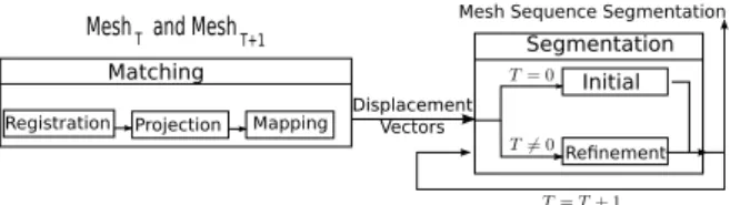
In this section, we describe the complete pipeline of the segmentation process (see Figure 1). The process can be roughly split, at each time step, into 2 parts: • matching (Sect.3).
• creation or refinement of the segmentation (Sect.4).
Mesh Sequence Segmentation Mesh T and Mesh T+1 Segmentation
Initial Refinement Matching
Registration Projection Mapping DisplacementVectors
Figure 1: Overall Pipeline of the segmentation. The algorithm takes as input a sequence of meshes with constant global topology. It registers the first mesh with the second. Displacement vectors between the ver-tices of the two frames are then computed using the re-sults of the registration.
Based on the displacement vectors, an initial segmen-tation of the first mesh into (i) stretched (and trans-lated), (ii) static and (iii) rigid regions is computed.
For each pair of successive frames in the sequence, we then apply the same matching process and compute the displacement vectors. The initial segmentation is then refined by analyzing the patches motion.
The segmentation of the sequence corresponds to the segmentation on the last frame, remapped on all frames of the sequence.
3
MATCHING PROCESS
The matching process consists of three successive stages: registration, projection and mapping, which
are described in the following subsections. At the end of the matching process, we have the displacement vectors of the vertices of the first frame all along the sequence and the matching of vertices in frame i with vertices in frame i+ 1 for 1 ≤ i < N.
3.1
Registration
It takes as input an unconstrained mesh sequence and registers it by pair of frames with the Coherent Point Drift algorithm (CPD) [MSCP07]. CPD is a probabilis-tic method for non-rigid registration of point sets. This method is robust to noise and outliers. Registration is performed between the vertices of all adjacent frames -vertices in frame Fi are registered with those in frame
Fi+1for i ranging from 1 to N-1 (see Fig 2 for the
no-tation) to obtain registered point sets Ri which are the
best alignment of the vertices in Fi with those in Fi+1.
The number of points in the resulting registered point set Riis equal to the number of vertices in Fi.
3.2
Projection
Each registered point set Ri obtained from the
previ-ous step is projected onto the surface of the subsequent frame Fi+1 so as to attain a better correspondence
be-tween the adjacent frames Fiand Fi+1. This projection
is performed in the following way:
• For each vertex on the surface of Fi+1, its normal
vector to the surface of the mesh is estimated. • For each point α in Ri, the vertexβ which is
clos-est to it in Fi+1is first searched. For each projected
point, the L2 norm with all the nodes on the surface is calculated and the node with the minimum norm is taken as the closest point of that projected point on the surface.
• Finally, every point α in Riis projected onto the
sur-face of Fi+1 along the normal vector of the
corre-sponding closest pointβ on the surface of Fi+1. The
projected point is denoted by Pi.
Using the above method, every point in Fi is projected
onto the surface of Fi+1to obtain Pifor i ranging from 1
to N− 1. The next step is to find the mapping between the vertices of the two adjacent frames.
3.3
Mapping
For sequences with constant number of vertices throughout the sequence, the correspondence between vertices of adjacent frames is easy to obtain. Every ver-tex in a frame has a corresponding verver-tex in the other frames in this case. However, such correspondences are not valid anymore when the number of vertices varies at every frame. In such cases, to establish corre-spondences between two adjacent frames Fi and Fi+1,
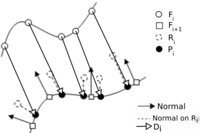
Di Fi Fi+1 Ri Pi Normal on Ri Normal
Figure 2: Matching Scheme.
in Fi+1which is closest to a point Ri(α) corresponds to
the vertex Fi(α). In this way, a unidirectional mapping
of all the vertices of Fi with the vertices of Fi+1 can
be computed to obtain Fii+1 , for i∈ [1, N − 1]. Such a mapping is essential if the trajectory of a vertex in a frame has to be followed along the successive frames of the sequence.
Two possible scenarios arise when registering adja-cent frames with unequal number of vertices. The first case is when the number of vertices in Fiis greater than
the number of vertices in Fi+1. In this case, more than
one point in Fimay be assigned to a vertex in Fi+1. On
the other hand, in the case when Fihas fewer vertices
than Fi+1, some vertices in Fi+1may not have any
cor-responding vertices in Fi. The unidirectional mapping
obtained between all adjacent frames can be extended to find the mapping of the vertices in a frame in all the subsequent frames using a recursive procedure. For each vertexα in frame Fi, the index of the
correspond-ing vertex in frame Fjis given by:
Fij(α) = Fjj−1((Fij−1(α))) where j ≥ i (1) The displacement vectors Di for each vertex in Fi are
calculated as follows: Di= Pi− Fi, i= 1 : N − 1, where
the points of Piare the projected points of Fion the
sur-face of Fi+1. Once these displacement vectors are
ob-tained, the displacement map of each vertex in the first frame can be constructed using the correspondences from the Fijarrays. The displacement map is the map-ping of vertices in the succeeding frames for each ver-tex in the first frame, i.e. the displacement map gives the corresponding vertex in any succeeding frame for each vertex in the first frame.
4
SEGMENTATION
4.1
Matching Process and Segmentation
In this section, we present our segmentation method. Our segmentation method relies on correct matching information (i.e. displacement vectors and matching
points). As long as this information is provided, any matching method can be used (not only the one we de-scribed in section 3). For instance, we also test our seg-mentation method using [KSMH09], where the match-ing is computed on the embeddmatch-ing of the meshes usmatch-ing Laplacian embedding (which “unfold” mesh). Segmen-tation results using this matching methods are discussed in Sect.5.2.
4.2
Outline
Our segmentation is a motion-based segmentation. We cluster vertices in rigid components, but contrary to pre-vious segmentation methods, we are also able to detect stretch motion. We are using a refinement method: 1. using the first two meshes and the associated
dis-placement vectors, we compute an initial segmenta-tion (secsegmenta-tion 4.4).
2. for all other frames of the sequence, we refine the previous segmentation by analyzing the current clus-ters and splitting them if necessary using displace-ment vectors and vertex matching (section 4.5). This refinement approach allows us to:
• process long sequences with lots of vertices. We re-quire only two meshes at a time in memory. • track transformations. We know at which frame a
cluster is created and its type of transformation. The segmentation of the sequence is the segmentation computed on the last frame. This segmentation is then remapped on the whole sequence using the matching information (section 4.6).
4.3
Errors
In the segmentation process, we use a metric denoted
as ET to sort clusters by errors. We use the method
proposed by Horn [Hor87] to compute the best possi-ble transformation between two set of points Piand Pj,
where card(Pi) = card(Pj) and points from Pihave
di-rect correspondent in Pj. Horn’s method returns a
trans-lation CT and a rotation CRsuch as Pj= CR∗ Pi+ CT.
For (Pi,Pj), ET can be defined as either:
• Average error: AE(Pi,Pj) =card1(Pi)
∑
pi∈PikCRpi+CT− pjk.
• Max error: ME(Pi,Pj) = max pi∈Pi
kCRpi+CT− pjk.
• Difference error: DE(Pi,Pj) = AE(Pi,Pj) −
4.4
Initial segmentation
The initial segmentation is applied on the first mesh F of the sequence. Using the displacement vectors ob-tained from the matching between the first two frames, we cluster vertices based on three categories, and clus-tering is applied successively:
1. static vertices: these vertices have no motion (clus-ters of static vertices are denoted as Cstatic).
2. stretched vertices: these vertices are in a stretched region (clusters of uniformly stretched vertices are denoted as Cstretched).
3. rigid vertices: motion of these vertices can be de-scribed by a rigid transformation (clusters of rigid vertices are denoted as Crigid).
Clusters are computed as follows. Static vertices are defined by displacement vectors whose norms are un-der a threshold Tstatic, vertices with a norm greater than
this threshold and with collinear (and in the same direc-tion) displacement vectors correspond to stretched ver-tices. They are gathered into connected regions. Rigid vertices are harder to compute. We use a modified ver-sion of the method described in [HAWG08]. To cluster them, we define the extended cluster ˜Ciof Cias Ciplus
its n closest points (in our experiments, n= 3 is suffi-cient).
The algorithm is:
1. Initialization: each vertex is a cluster.
2. For each cluster, compute the optimal transforma-tion [Hor87] which maps ˜C of first frame to sec-ond frame. Points of secsec-ond frame are reconstructed from points of ˜Cand their associated displacement vectors. Take the cluster Ciwith the smallest
trans-formation error Et(defined in section 4.3).
3. For all clusters Cj which intersect ˜Ci, apply the
transformation found for Ci to each point of Cj. If
the error is under a threshold Ttrans f, merge Cj to
Ci. If no merging happens, take the cluster with the
smallest error apart from Ci, and do the same. Here
the error is defined as the maximum distance be-tween the transformed point of Cjand the displaced
point of Cj.
4. Repeat steps 2 and 3 while merging is possible. As previously outlined, the order in which the clus-tering is performed is important. The algorithm first computes Cstatic and Cstretched. It then builds a
sub-mesh Fs= F \ (Cstatic∪ Cstretched). Rigid clusters are
computed at the end on Fs, in order to avoid
overlap-ping of rigid regions over static and stretched ones. To avoid small clusters, i.e whose size is inferior to 3% of
the mesh, due to noise or small areas around articula-tions, we merge them to the neighbouring cluster which minimizes the error as in step 3 of the rigid clustering process.
At the end of the initial segmentation process, the mesh of the first frame is decomposed in clusters of dif-ferent types based on the displacement vectors between the two first frames. The segmentation is then refined using following frames, after each matching.
4.5
Refinement
The refinement aims at finding new regions which may appear on a new frame. Each cluster is decomposed (if necessary) into sub-clusters. The process starts from the clusters found at the previous step, i.e. the initial segmentation for frame 2, or the previous refinement in the other cases. It also uses the displacement vectors computed during the matching process. The refinement is done in two steps:
• check previous clusters. • find new clusters.
A quick checkout step is used to avoid to re-create the same cluster. We check that:
• for static clusters, all displacement vectors norms in a cluster are below the threshold Tstatic;
• for stretched clusters, displacement vectors are still collinear and with the same direction;
• for rigid clusters, the best transformation between the points of cluster Ciat frame F and frame F+ 1
is valid. This transformation is computed using
Horn’s method [Hor87] (applied to points recon-structed from the previous frame and from the dis-placement vectors) If the associated error is above
Ttrans f, the transformation is considered as not valid.
All clusters which are still valid are kept unchanged. All other clusters correspond to regions where new transformations are starting. These clusters are decom-posed into sub-clusters:
• If the new transformation applies to a whole cluster, this cluster is kept and not decomposed.
• Else, this cluster is decomposed.
This decomposition is similar to the one applied in the initial segmentation: for each cluster Ccof the list, the
algorithm computes static vertices, stretched vertices and rigid vertices. As before, static and stretched sub-clusters are computed first and added to the sets of static Cstatic and stretch Cstretch clusters. Fs= F \ (Cstatic∪ Cstretch) is built. Contrary to initial segmentation, the rigid clustering is not applied on Fs, but on Fs∩ Cc, to
make sure that the transformation applies on Cc. These
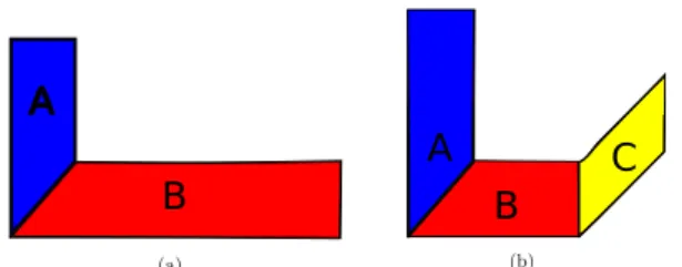
clusters are added to the set of rigid clusters (See Fig-ure 3).
A
B
A
B
C
Figure 3: Refinement example: (a) Segmentation at
time F. (b) Segmentation at time F+ 1. Cluster B is
refined into sub-cluster B and C because of the rotation.
(a) (b)
Figure 4: Matching result: (a) Full matching, (b) Partial matching.
4.6
Remapping
Once all frames have been segmented, we report the segmentation of the last frame on the whole sequence using matching information. As some points can be un-matched, when we report the segmentation from one frame to the other, we apply a region growing method to avoid holes in the segmentation. For each unmatched point pi, we search for the cluster C which contains the
maximun number of points in pineighbourhood and set
piin C.
5
RESULTS AND DISCUSSION
5.1
Matching
Matching results are shown in Figure 4 where the cor-respondences of vertices between different frames of the horse gallop sequence are displayed. The displace-ment vectors of these corresponding vertices in the suc-ceeding frames are then used in the segmentation pro-cess. On a standard personal computer (core 2 duo, 2.33 GHz), matching of one mesh (8199 vertices) with an-other vertices (7254) takes 13 minutes. The implemen-tation is performed with MATLAB using a fast imple-mentation of the CPD algorithm based on a fast Gaus-sian transform. In the matching process, the registration of adjacent frames is the major bottleneck as compared to the projection and mapping parts.
5.2
Segmentation
Setting of Thresholds and Errors
To handle noise present on unconstrained mesh se-quence, we use the threshold Tstatic. For the decimated
horse sequence (see Fig.8), we use a threshold of
1× 10⁻⁴, the bounding box of the mesh is 12.3177 .
The threshold Ttrans f corresponds to the motion
ampli-tude tolerated for a cluster on dynamic mesh between two frames. For unconstrained mesh sequence, this threshold should incorporate the slight error of the projected points which contain a small error contrary to models created in a modeler. Segmentation can be refined using different values for Ttrans f: small values
produce more clusters as shown in Fig.6. This thresh-old does not depend on vertex density but depends on the amplitude movement between 2 frames.
In our experiments, the Difference Error should be preferred when dealing with dynamic meshes. Indeed, Difference Error avoids to merge clusters with large er-rors. Clusters with large errors in dynamic meshes are due to change in transformation. On presence of noise and outliers, the Difference Error is too sensible and Average Error becomes the best error type: large error can result from outliers/noise in clusters. Such clus-ter should not be discarded if it has few outliers. Fig.5 shows the different errors applied on a dynamic mesh and on a dynamic mesh perturbed with some noise (noise is applied independently on each frame).
Results
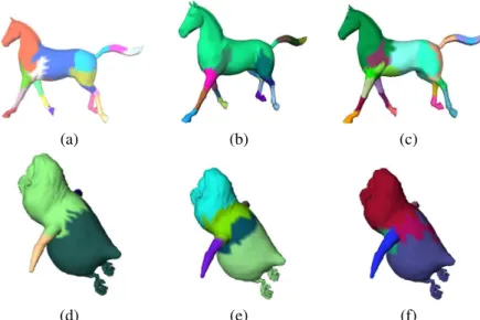
Fig.6 shows the result of our algorithm applies to a dynamic mesh compared to [LWC06] and [dATTS08]. As can be seen, our method yields similar results. The main difference with [LWC06] deals with cluster’s boundaries: they are not smooth. We do not apply a post-processing stage as boundaries are not clearly defined on an unconstrained mesh sequence (see next section for a discussion on boundaries).
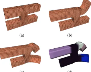
Contrary to previous methods, we handle stretch de-formations. We show some results of such clustering on Fig.7. Some parts of the object follow a rigid trans-formation while others are stretched.
Our algorithm is able to segment unconstrained mesh sequences as shown in Fig.8. Each frame of the horse sequence is randomly decimated, and we segment this sequence. The number of vertices varies from 2624 to 4696. Segmentation is similar to the dynamic one.
Discussion
Our whole process deals with two frames at a time, meaning:
• mesh sequences with a high number of frames and/or vertices can be processed.
• the apparition and the decomposition of each cluster is controlled.
(a) (b) (c)
(d) (e) (f)
Figure 5: Comparison of error type on segmentation result. (a) Average Error, (b) Difference Error and (c) Max Error on dynamic mesh. (d) Average Error, (e) Difference Error and (f) Max Error on noisy mesh.
(a) (b) (c) (d)
(e) (f) (g) (h)
Figure 6: Horse Segmentation: (a) [LWC06], (b) [dATTS08], (c) with our method. (d,e,f) Frames of the sequence. (g) Coarse, Ttrans f = 0.0015 and (h) refined, Ttrans f = 0.0007 result, to compare with (c), Ttrans f = 0.0009.
Boundaries There are two closely related issues on
cluster boundaries: they are not smooth and bound-aries of clusters on articulation are not necessarily on the middle of the articulation as with other methods. They can be around, a little bit after or before (see Fig.9 for illustration). Clusters are merged while the trans-formation (see section 4.4) found can be applied, this transformation becomes invalid after/before the bound-aries. As we deal with meshes with varying connec-tivity, boundaries move from one frame to another. As we want to work on these original sequences (i.e with no modification), this is acceptable. Otherwise, a post-processing step can correct this problem by inserting points on boundaries in all frames.
Noise and outliers The presence of some outliers or
badly matched points is similar to noise. Usage of
aver-age error merge them with other vertices. The remain-ing outliers are on their own cluster, and these clusters are smalls. This means that they are handled by the forced merge of small clusters. However, in presence of many grouped outliers, our algorithm produces in-correct results, as they are clustered together (but the segmentation is coherent with the matching informa-tion). It also produces incorrect results when many badly matched points are present: it forces user to select large threshold value. This means that it can produce only a coarse segmentation. In this case the segmen-tation is correct on the first frame, but it is incorrectly remapped on following frames.
Errors coming from matching and outliers which
(a) (b)
(c) (d)
Figure 7: Stretch: (a), (b), (c) frames of the sequence. (d) segmentation.
(a) (b)
(c)
Figure 8: Segmentation on a decimated horse sequence. (a) Result. (b,c) Minimum and maximum number of vertices. Object at Time T Object at Time T+1
Boundary on the middle of the articulation
Boundaries before/after the middle of the articulation
Figure 9: Boundaries on articulation.
following frames. This is due to the nature of our
algorithm.
Matching Methods We have chosen to use projected
points to obtained the displacement vectors. The con-sequence is that we have “real” displacement vectors, but with an expensive computation cost. Using an al-gorithm as in [MHK+08], which does not provide pro-jected points, we have to use the matched point to com-pute the displacement vectors. This implies an error
which is more important than with our method. On a dense mesh, this is not be important, as matched point are close to the projected one. However, on sparse meshes, the error can be big enough to either:
• give incorrect result.
• force user to use large Ttrans f (and obtained a coarse
segmentation).
Implementation The prototype for the segmentation
part is written in C++ using CGAL, while the matching part is written in Matlab.
Future Work The proposed method can be improved in several ways:
• we did not test our method with objects facing global topological changes. We do not see any trouble in handling them: for each pair of successive frames, detect topological changes between them and split clusters concerned by the topological change of the object;
• The algorithm currently works using two successive frames, which means that we can miss slow motions: if the deformation between two frames is too small, the checkout on the refinement process will always be true and the algorithm will not refine the clus-ter. The threshold Ttrans f limits this problem but
working with a small time window (as it can eas-ily fit in memory) can improve this. We have some preliminary results, but the main difficulty consists in automatically detecting the size of this time win-dow. Time window may help to correct invalid clus-ter subdivision by inspecting following frames. • Detect new motion type such as twist.
The main objective of our next work is to define a validation framework, using user validation and defin-ing error criteria to validate mesh sequence segmenta-tion [BVLD09, CGF09].
6
CONCLUSION
We have presented a complete framework to segment mesh sequences with varying number of vertices
in rigid and stretch components. Our segmentation
method works on the fly and allows us to track defor-mation all along the sequence. Extension to handle objects facing global topological changes, time window to segment slow motion and temporal matching to take advantage of temporal coherency are planned for the near future. This method can be integrated in an automatic production chain, however the threshold needs to be determined manually before. There is no limit to the number of vertices or frames that can be treated by our method, but since errors are passed from frame to frame, long sequence should be splitted into shorter ones.
7
AFFILIATIONS
Romain Arcila:1,2,3,4
S. Kartik Buddha,Florence Denis, Florent Dupont:1,2 Franck Hétroy:3,4
1Université de Lyon, CNRS
2Université Lyon 1, LIRIS, UMR5205, F-69622, France 3Université de Grenoble & CNRS, Laboratoire Jean Kuntz-mann, Grenoble, France
4INRIA Grenoble - Rhône-Alpes, Grenoble, France
8
ACKNOWLEDGMENT
This work is partially supported by the ANR (Agence Na-tionale de la Recherche) through MADRAS project (ANR-07-MDCO-015).
A static mesh and mesh sequence repository can be found at http://www-rech.telecom-lille1.eu/madras/
REFERENCES
[AS07] R. Amjoun and W. Straßer. Efficient compres-sion of 3d dynamic mesh sequences. In Journal
of the WSCG, 2007.
[BVLD09] Halim Benhabiles, Jean-Philippe Vandeborre, Guillaume Lavoué, and Mohamed Daoudi. A framework for the objective evaluation of seg-mentation algorithms using a ground-truth of hu-man segmented 3D-models. In IEEE Interna-tional Conference on Shape Modeling and
Ap-plications (Shape Modeling International 2009),
Beijing, China, June 26-28 2009. short paper.
[CGF09] Xiaobai Chen, Aleksey Golovinskiy, and
Thomas Funkhouser. A benchmark for 3D mesh segmentation. ACM Transactions on Graphics
(Proc. SIGGRAPH), 28(3), August 2009.
[CMK+08] F. Cuzzolin, D. Mateus, D. Knossow, E. Boyer, and R. Horaud. Coherent laplacian 3-d pro-trusion segmentation. In Proceedings of the IEEE Conference on Computer Vision and
Pat-tern Recognition, pages 1–8, 2008.
[dATTS08] E. de Aguiar, C. Theobalt, S. Thrun, and H.P. Seidel. Automatic Conversion of Mesh Ani-mations into Skeleton-based AniAni-mations. vol-ume 27, pages 389–397, 2008.
[GWH01] M. Garland, A. Willmott, and P.S. Heckbert. Hi-erarchical face clustering on polygonal surfaces. In I3D ’01: Proceedings of the 2001 symposium
on Interactive 3D graphics, pages 49–58, 2001.
[HAWG08] Q. Huang, B. Adams, M. Wicke, and L.J. Guibas. Non-rigid registration under isomet-ric deformations. Computer Graphics Forum, 27(5):1449–1457, 2008.
[Hor87] B.K.P. Horn. Closed-form solution of absolute orientation using unit quaternions. J. Opt. Soc.
Am. A, 4(4):629–642, 1987.
[JZvK07] V. Jain, H. Zhang, and O. van Kaick.
Non-rigid spectral correspondence of triangle meshes. International Journal on Shape
Mod-eling, 13(1):101–124, 2007.
[KG00] Z. Karni and C. Gotsman. Spectral compression of mesh geometry. In Siggraph 2000, Computer
Graphics Proceedings, pages 279–286, 2000.
[KSMH09] David Knossow, Avinash Sharma, Diana Ma-teus, and Radu Horaud. Inexact matching of large and sparse graphs using laplacian eigen-vectors. In GbRPR ’09: Proceedings of the 7th IAPR-TC-15 International Workshop on
Graph-Based Representations in Pattern Recognition,
pages 144–153. Springer-Verlag, 2009. [Len99] J.E. Lengyel. Compression of time-dependent
geometry. In I3D ’99: Proceedings of the 1999
symposium on Interactive 3D graphics, pages
89–95, 1999.
[LPRM02] B. Lévy, S. Petitjean, N. Ray, and J. Maillot. Least squares conformal maps for automatic tex-ture atlas generation. In ACM SIGGRAPH
con-ference proceedings, pages 362–371, 2002.
[LTA08] N.S. Lee, T.Yamasaki, and K. Aizawa. Hierar-chical mesh decomposition and motion tracking for time-varying-meshes. In ICME, pages 1309– 1312, 2008.
[LWC06] T.-Y. Lee, Y.-S. Wang, and T.-G. Chen. Seg-menting a deforming mesh into near-rigid com-ponents. Vis. Comput., 22(9):729–739, 2006. [MHK+08] Diana Mateus, Radu P. Horaud, David Knossow,
Fabio Cuzzolin, and Edmond Boyer. Articulated shape matching using laplacian eigenfunctions and unsupervised point registration. In Proceed-ings of the IEEE Conference on Computer Vision
and Pattern Recognition, 2008.
[MSCP07] A. Myronenko, X. Song, and M.
Carreira-Perpinan. Non-rigid point set registration: Co-herent point drift. In Advances in Neural
In-formation Processing Systems (NIPS) 19, pages
1009–1016. 2007.
[SC06] A. Sundaresan and R. Chellappa. Acquisition of articulated human body models using multiple cameras. Lecture Notes in Computer Science,
Proceedings of AMDO, 4069:78–89, 2006.
[SH07] J. Starck and A. Hilton. Correspondence
la-belling for wide-timeframe free-form surface matching. In ICCV, pages 1–8, 2007.
[Sha08] A. Shamir. A survey on mesh segmentation tech-niques. Computer Graphics Forum, 27(6):1539– 1556, 2008.
[VZBH08] K. Varanasi, A. Zaharescu, E. Boyer, and R.P. Horaud. Temporal surface tracking using mesh evolution. In Proceedings of the Tenth European
Conference on Computer Vision, volume Part II,
pages 30–43, 2008.
[Zuc02] E. Zuckerberger. Polyhedral surface decomposi-tion with applicadecomposi-tions. Computers and Graphics, 26(5):733–743, 2002.