Publisher’s version / Version de l'éditeur:
Vous avez des questions? Nous pouvons vous aider. Pour communiquer directement avec un auteur, consultez la première page de la revue dans laquelle son article a été publié afin de trouver ses coordonnées. Si vous n’arrivez pas à les repérer, communiquez avec nous à [email protected].
Questions? Contact the NRC Publications Archive team at
[email protected]. If you wish to email the authors directly, please see the first page of the publication for their contact information.
https://publications-cnrc.canada.ca/fra/droits
L’accès à ce site Web et l’utilisation de son contenu sont assujettis aux conditions présentées dans le site LISEZ CES CONDITIONS ATTENTIVEMENT AVANT D’UTILISER CE SITE WEB.
Internal Report (National Research Council of Canada. Institute for Research in
Construction), 1987-03-01
READ THESE TERMS AND CONDITIONS CAREFULLY BEFORE USING THIS WEBSITE.
https://nrc-publications.canada.ca/eng/copyright
NRC Publications Archive Record / Notice des Archives des publications du CNRC : https://nrc-publications.canada.ca/eng/view/object/?id=bfbf2f60-751b-4d48-892a-65ff024e9f56 https://publications-cnrc.canada.ca/fra/voir/objet/?id=bfbf2f60-751b-4d48-892a-65ff024e9f56
NRC Publications Archive
Archives des publications du CNRC
For the publisher’s version, please access the DOI link below./ Pour consulter la version de l’éditeur, utilisez le lien DOI ci-dessous.
https://doi.org/10.4224/20337879
Access and use of this website and the material on it are subject to the Terms and Conditions set forth at
NRCC Air Collector Test Facility: Description, Calibration and Data
Manipulation
'
R427
National Research Conseil national
C .
'
O2
b
Council Canada de recherchu Canada1
BTDG
- -.1
Institute for lnstitut deResearch in recherche en
Construction construction
NRCC Air Collector Test Facility:
Description, Calibration and Data Manipulation
M.A. Bernier
Internal Report No.
524
Date
of issue: March
1987
This is an internal report of the lnstitute for Research in Construction. It is for personal use only and is not to be cited as a reference in any publication.
ABSTRACT
This r e p o r t d e s c r i b e s t h e e x p e r i m e n t a l f a c i l i t y used t o t e s t a i r s o l a r c o l l e c t o r s a t t h e I n s t i t u t e f o r Research i n C o n s t r u c t i o n ( f o r m e r l y t h e D i v i s i o n of B u i l d i n g Research) of t h e N a t i o n a l Research Council Canada. It a l s o p r e s e n t s d a t a manipulation and r e d u c t i o n t e c h n i q u e s . F i n a l l y , t h e t e c h n i q u e s used t o c a l i b r a t e t h e f a c i l i t y and t h e c a l i b r a t i o n a r e discussed. NOMENCLATURE A C o l l e c t o r a p e r t u r e a r e a (m2) At O r i f i c e p l a t e a r e a (m2) C Discharge c o e f f i c i e n t ( d i m e n s i o n l e s s ) A i r s p e c i f i c h e a t (J1kg.K) P O r i f i c e p l a t e d i a m e t e r (m) D P i p e d i a m e t e r (m) E V e l o c i t y of approach f a c t o r ( d i m e n s i o n l e s s ) G Global i r r a d i a n c e i n c i d e n t on t h e c o l l e c t o r (w/m2) k I s e n t r o p i c c o e f f i c i e n t ( d i m e n s i o n l e s s )
5
I n l e t mass f l o w r a t e ( k g / s ) m O u t l e t mass f l o w r a t e ( k g / s )4,
Leakage mass f l o w r a t e ( k g / s ) P1 Absolute p r e s s u r e a t t h e upstream p e s s u r e t a p s ( P a );:"
Power i n p u t t o t h e C a l i b r a t i o n Heat Source (W) I n l e t gauge p r e s s u r e t o t h e c o l l e c t o r (Pa) Po O u t l e t gauge p r e s s u r e t o t h e c o l l e c t o r (Pa) Qc C o l l e c t e d energy(W)
Re Reynolds number ( d i m e n s i o n l e s s ) T1 Absolute t e m p e r a t u r e a t t h e upstream p r e s s u r e t a p s (K) T, Ambient t e m p e r a t u r e (OC) T i I n l e t t e m p e r a t u r e t o t h e c o l l e c t o r (OC) To O u t l e t t e m p e r a t u r e t o t h e c o l l e c t o r ("C) TL A i r l e a k a g e t e m p e r a t u r e (OC) T ~ o A i r l e a k a g e t e m p e r a t u r e (OC) Sky t e m p e r a t u r e (K)?
Humidity r a t i o (kg H20/kg d r y a i r ) a Stefan-Boltzmann c o n s t a n t ( w / ~ * . K ~ ) AP P r e s s u r e d i f f e r e n t a c r o s s t h e o r i f i c e p l a t e ( P a ) AT Temperature d i f f e r e n c e a c r o s s t h e c o l l e c t o r (K) t7 Thermal e f f i c i e n c y ( X ) YGas
expansion f a c t o r ( d i m e n s i o n l e s s ) p 1 A i r d e n s i t y a t t h e upstream p r e s s u r e t a p s l o c a t i o n (kg/m3) b A i r v i s c o s i t y ( ~ * s / m ~ )@
d/D ( d i m e n s i o n l e s s ) 1.0 I n t r o d u c t i o n The I n s t i t u t e f o r Research i n C o n s t r u c t i o n ( f o r m e r l y t h e D i v i s i o n of B u i l d i n g Research) of t h e N a t i o n a l Research Council of Canada was i n v o l v e d from 1981 t o 1985 i n t h e development of improved thermal performance t e s tmethods and equipment and better characterizations of air solar collectors thermal performance. Thermal performance test methods and characterizations of air solar collectors will be the subject of another paper
(1).
This report describes the facility used at NRCC to test air collectors. The test facility was bought from the Ontario Research Foundation, who had built similar devices for solar collector commercial testing at the CanadianNational Solar Test Facility (2). The facility was modified by NRCC to suit research needs. This note is an account of the hardware and software
modifications made to the test facility. As well, a thorough calibration, which is also reported here, was undertaken to minimize experimental
uncertainty.
2.0 Description of the facility 2.1 Altazimuth frame
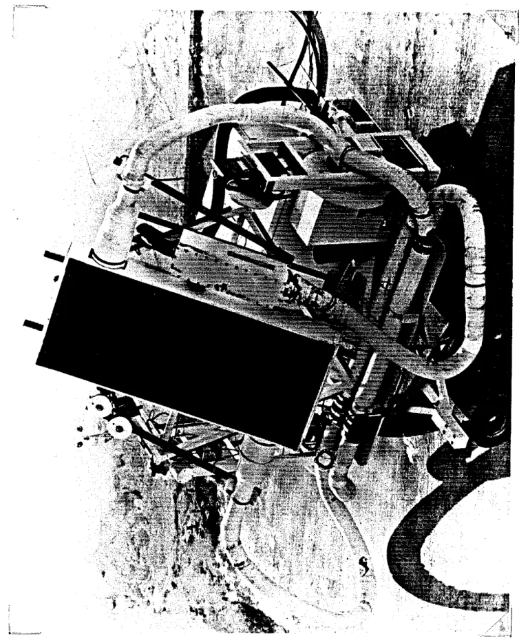
The experimental test facility (Fig. 1) rests on four rubber tire
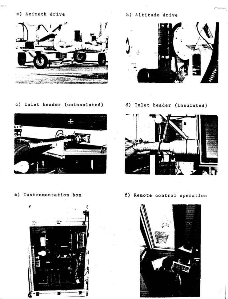
wheels and rotates around two axes (altazimuth tracking). It is anchored to a leveled concrete pad (7 m x 7 m, 114' slope allowed for water drainage) via two removable keys (Fig. 2a). With the keys disengaged, the frame can easily be wheeled inside for servicing. Whenver required, an automatic snow melting system is activated to keep the pad free of snow and ice.
A vertical shaft, through a DC motor-worm-gear-chain drive arrangement, provides the azimuth (east-west) rotation. The altitude drive includes two parts: An enclosed worm gear with a DC motor and an open worm gear drive (Fig. 2b). The altitude axle rotates in two pillow block bearings.
Both movements are computer controlled. The computer, using the date and time entered by the operator, positions the altazimuth frame so that the face of the collector is perpendicular to the sun's rays. Potentiometers located on each shaft feed back to the computer the actual position and the computer, by activating the azimuth and /or the altitude drive, makes the necessary adjustments so that the tracking is always within * l o . These corrections occur approximately once every minute. Limit switches are strategically located on each shaft to prevent over-travel.
2.2 Meteorological measurements 2.2.1 Radiation measurements
The global (beam
+
diffuse) solar radiation striking the collector is measured using a calibrated Precision Spectral Pyranometer. The PSP is mounted on the tracking altazimuth frame with it's sensing surface coplanar to the collector glazing surface as recommended by ASHRAE Standard93-77 (3).
The beam component of solar radiario~l is ~uraaurad using a calibrated NIP (Normal Incidence Pyrheliometer) mounted on a precise sun tracking device and located on the roof of a nearby building. The amount of diffuse solar radiation received by the collector is not measured; it is simply calculated as the difference between the readings of the PSP and the NIP.
Long wave r a d i a t i o n ( t h e r m a l sky r a d i a n c e ) i s measured u s i n g a
pyrgeometer. The t h e r m o p i l e v o l t a g e o u t p u t of t h i s i n s t r u m e n t i s a f u n c t i o n of i t s temperature, which i s determined by t h e balance between absorbed and e m i t t e d l o n g wave r a d i a t i o n f l u x e s . An i n t e r n a l t h e r m i s t o r - b a t t e r y -
r e s i s t a n c e c i r c u i t produces a v o l t a g e p r o p o r t i o n a l t o uT4, where T i s t h e a b s o l u t e t e m p e r a t u r e of t h e instrument. T h i s a n a l o g v o l t a g e c a n be added t o t h e thermopile o u t p u t i n o r d e r t o o b t a i n o n l y t h e downcoming long wave
r a d i a t i o n , oTsky4, where T is t h e e q u i v a l e n t sky temperature. The sky
pyrgeometer i s mounted on t h e a l t a z i m u t h frame and i t s s e n s i n g s u r f a c e i s c o p l a n a r w i t h t h e c o l l e c t o r s u r f a c e .
2.2.2 Ambient t e m p e r a t u r e
The ambient t e m p e r a t u r e i s measured u s i n g a five-element s i l i c o n t e m p e r a t u r e s e n s o r e n c a p s u l a t e d i n a 6 mm s t a i n l e s s - s t e e l t u b e which i s i n s e r t e d i n a n a s p i r a t e d t e m p e r a t u r e - r a d i a t i o n s h i e l d .
2.2.3 Wind speed
Wind speed i s measured u s i n g a micro response t h r e e cup anemometer equipped w i t h a DC g e n e r a t o r producing a DC v o l t a g e p r o p o r t i o n a l t o wind speed. The anemometer i s p o s i t i o n e d , a s recommended by ASHRAE Standard 93-77 ( 3 ) , a t approximately mid-collector h e i g h t , i . e . 2.4 m above ground, and i s mounted on t h e a l t a z i m u t h frame ( s e e Fig. 1).
2.3 A i r flow c i r c u i t
A s c h e m a t i c of t h e t e s t l o o p
i s
shown i n Fig. 3. The a i r flow c i r c u i t i s a n open loop. The two-blower c o n f i g u r a t i o n p e r m i t s t h e v a r i a t i o n of i n l e t p r e s s u r e and f l o w r a t e t o t h e c o l l e c t o r . Ambient a i r e n t e r s t h e c i r c u i t a t t h e i n t a k e of t h e i n l e t blower. Two plug v a l v e s l o c a t e d a t t h e d i s c h a r g e of t h e blower permit t h e manual c o n t r o l of i n l e t mass f l o w r a t e and p r e s s u r e . Then t h e a i r t r a v e l s s u c c e s s i v e l y from t h e i n l e t h e a t e r t o t h e upstream o r i f i c e p l a t e , t o t h e i n l e t p r e s s u r e t a p e and t o t h e i n l e tt e m p e r a t u r e measuring s e c t i o n . The a i r e n t e r s t h e c o l l e c t o r a t t h e bottom, e x i t s a t t h e t o p where t h e o u t l e t t e m p e r a t u r e and p r e s s u r e a r e measured, e n t e r s t h e downstream o r i f i c e p l a t e s e c t i o n and f i n a l l y ends up a t t h e s u c t i o n blower. The o u t l e t mass f l o w r a t e i s r e g u l a t e d by b l e e d i n g a i r through a c o m p u t e r c o n t r o l l e d bypass.
The p i p i n g h a s a nominal p i p e d i a m e t e r of 100 mm. A l l of t h e f l e x i b l e p i p i n g i s of t h e wire-helix type. A t t h e m e t a l - f l e x i b l e p i p e j u n c t i o n s t h e m e t a l p i p e i s h e a v i l y coated w i t h high vacuum g r e a s e b e f o r e being i n s e r t e d
(approx. 50 mm) i n t o t h e f l e x p i p e and f a s t e n e d t o i t w i t h a hose clamp. The p i p i n g
i s
i n s u l a t e d w i t h 20 mm of Armaflex i n s u l a t i o n . The Armaflex i s p a i n t e d w h i t e t o reduce s o l a r g a i n s . T r a n s i t i o n s p i e c e s a r e o f t e n r e q u i r e d a t t h e i n l e t and o u t l e t of t h e c o l l e c t o r t o go from, f o r example, a round p i p e a t t h e t e m p e r a t u r e measuring s e c t i o n s t o r e c t a n g u l a r e n t r a n c e s a t t h e c o l l e c t o r i n l e t (Fig. 2c). The h e a d e r s , i . e . t h e p i p e s e c t i o n s from t h e t e m p e r a t u r e measuring l o c a t i o n s t o t h e c o l l e c t o r , a r e i n s u l a t e d w i t h 75 mm of f i b e r g l a s s p i p e i n s u l a t i o n and covered w i t h w h i t e waterproof t a p e2.4 Mass f l o w r a t e measurements
Measurements of mass f l o w r a t e a r e made upstream and downstream of t h e c o l l e c t o r u s i n g two nominally i d e n t i c a l o r i f i c e p l a t e s e c t i o n s b u i l t
a c c o r d i n g t o ASME and IS0 procedure ( 4 , 5 ) . By s e l e c t i n g one of f i v e o r i f i c e p l a t e s , c o l l e c t o r s c a n b e t e s t e d a t f l o w r a t e s up t o 0.20 kg/s w h i l e
m a i n t a i n i n g a r e l a t i v e l y h i g h p r e s s u r e drop through t h e o r i f i c e s ( t y p i c a l l y ,
AP s LOO0 Pa). The c a l c u l a t i o n p r o c e d u r e a s w e l l a s c o n s t r u c t i o n d e t a i l s of
t h e o r i f i c e p l a t e s e c t i o n s a r e p r e s e n t e d i n Appendix A.
2.5 D i f f e r e n t i a l t e m p e r a t u r e measurement
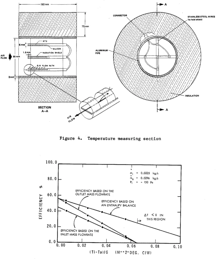
I n l e t and o u t l e t t e m p e r a t u r e s a r e measured u s i n g b o t h s i l i c o n t r a n s i s t o r s and platinum r e s i s t a n c e t e m p e r a t u r e s e n s o r s . To o b t a i n t h e average t e m p e r a t u r e through t h e p i p e s e c t i o n and d e c r e a s e t h e measurement u n c e r t a i n t y , e a c h t y p e of s e n s o r i s arranged i n a n a r r a y of f i v e elements connected i n s e r i e s (Fig. 4). Temperature measurement e r r o r s due t o r a d i a t i o n exchange between t h e s e n s o r s and t h e d u c t w a l l a r e minimized by i n s u l a t i n g t h e t e m p e r a t u r e measurement s e c t i o n w i t h 75 mm of f i b e r g l a s s i n s u l a t i o n and by p a r t i a l l y s h i e l d i n g e a c h s e n s o r w i t h a s t a i n l e s s - s t e e l tube. The s i l i c o n s e n s o r s have a n e g a t i v e t e m p e r a t u r e c o e f f i c i e n t and t h e platinum ones have a p o s i t i v e c o e f f i c i e n t , s o t h a t a n e r r o r due t o a d r i f t i n t h e computer's
AID
c o n v e r t e r can be d e t e c t e d a s a n a p p a r e n t divergence of t h e i n l e t t e m p e r a t u r e r e a d i n g s .During c o l l e c t o r t e s t i n g , i n l e t and o u t l e t t e m p e r a t u r e measurements a r e t a k e n a t some d i s t a n c e from t h e a c t u a l i n l e t and o u t l e t of t h e c o l l e c t o r . Even though h e a d e r s a r e i n s u l a t e d , h e a t l o s s e s occur. I f no c o r r e c t i o n i s a p p l i e d t h e s e l o s s e s might i n t r o d u c e a s i g n i f i c a n t s y s t e m a t i c e r r o r on t h e t e m p e r a t u r e d i f f e r e n c e . T h e r e f o r e , d i f f e r e n t i a l t e m p e r a t u r e r e a d i n g s a r e c o r r e c t e d a c c o r d i n g t o t h e procedure o u t l i n e d i n ( 6 ) .
2.6 R e l a t i v e humidity
The r e l a t i v e humidity i s measured u s i n g a c a p a c i t i v e t h i n - f i l m humidity sensor. The s e n s o r i s l o c a t e d n e a r t h e i n t a k e of t h e i n l e t blower and i s
p r o t e c t e d by a s m a l l "Stephenson" s c r e e n e n c l o s u r e . 2.7 I n l e t and o u t l e t p r e s s u r e t a p s e c t i o n s
The i n l e t and o u t l e t gauge p r e s s u r e s were measured u s i n g a d i g i t a l micromanometer connected t o a piezometer r i n g (Fig. 2c). The r i n g , which i s s i m i l a r t o t h e o r i f i c e p l a t e piezometer r i n g , p e r m i t s t h e a v e r a g i n g of j t h e p r e s s u r e around t h e c i r c u m f e r e n c e of t h e pipe. It i s preceeded by 0.45
m
of s t r a i g h t pipe. S i n c e t h e i n l e t and o u t l e t gauge p r e s s u r e s a r e n o t measured a t t h e a c t u a l i n l e t and o u t l e t of t h e c o l l e c t o r , a p r e s s u r e drop t e s t i s neccaaary and c o r r e c t i o n i s a p p l i e d t o o b t a i n t h e a c t u a l i n l e t and o u t l e t gauge p r e s s u r e s . I n t h e p r e s s u r e d r o p t e s t , t h e c o l l e c t o r i s removed and both h e a d e r s a r e b o l t e d t o g e t h e r w i t h a p i t o t t u b e i n s e r t e d a t t h e j u n c t i o n . The f a n s a r e t h e n a c t i v a t e d and t h e s t a t i c p r e s s u r e d r o p between t h e i n l e t p r e s s u r e t a p and t h e j u n c t i o n and t h e p r e s s u r e drop between t h e j u n c t i o n and t h e o u t l e t p r e s s u r e t a p a r e measured.2.8 Inlet heater
The air temperature at the collector inlet was controlled within +O.Z°C of the set point by a computer-regulated, multi-element strip heater
(9.4 kW). 2.9 Computer
The on-board computer is a Z8OA based microcomputer with 38 Kbytes of read-onlymemory (ROM) and 26 Kbytes of random access memory
(RAM).
It has a 16 channel,12
bit bipolar analog to digital input circuit for dataacquisition and a digital output circuit for control. The computer is located inside an instrumentation box (Fig. 2e). It is accessed via a remote terminal located in an office overlooking the test site (Fig. 2f). 2.10 Typical test
Some operations are necessary before actual testing can start, typically the pre-test procedure goes as follows:
1. The collector surface and all radiation measuring instruments are cleaned to remove any dust or dirt accumulation.
2. An opening is made in the loop by unfastening one of the metal-flexible pipe joint to prevent abnormal pressures in the loop as start-up.
3. The two blowers are started. Manual adjustments on the plug valves and on the bypass are made to obtain the required thermal performance test flowrate, as determined by the computer, upstream and downstream of the collector.
4.
The metal-flexible pipe joint is refastened.5. Final adjustments are made on the plug valves and on the bypass so as to obtain the desired inlet flowrate and pressure.
3.0 Data Manipulation 3.1 Data Acquisition
After the pre-test procedures have been completed (Section 2.10) and before the actual testing period, a series of instructions must be sent to the on-board computer in order to inform it of the required thermal
performance test conditions. These instructions are performed sequentially after execution has been initiated. Some of the most important commands are described below:
INSTRUCTIONS (in order of execution)
EXPLANATION
FS0.0720
-
Flow Let; sets the inlet flow to 0.0720 kgls TS22.0-
Temperature Set; sets the inlet temperature tov a r i a b l e i n l e t temp. i n l e t flow
t r a c k i n g accuracy
Wait f o r Control; a l l f u r t h e r commands a r e
-
stopped u y t i l t h e i n l e t t e m p e r a t u r e , t h e f l u i d f l o w r a t e and frame azimuth and a l t i t u d e have reached t h e i r set p o i n t and maintained i t
w i t h i n a c e r t a i n r a n g e f o r a s p e c i f i e d l e n g t h of time. T y p i c a l l y t h e f o l l o w i n g ranges were used:
range
l e n g t h of time fl.O°C 300 s e c . f0.00025 k g / s 300 s e c . i 1 ° 10 s e c . A f t e r c o n t r o l (WC) h a s been achieved e x e c u t i o n i s suspended u n t i l t h e Wait f o r Time command h a s e l a p s e d ( t y p i c a l l y 900 s e c ) . Usually a f t e r t h i s "soak" p e r i o d t h e t e m p e r a t u r e r i s e through t h e c o l l e c t o r i s s t a b l e .Wait f o r S t a b i l i t y : During t h i s p e r i o d t h e
-
computer Thecks ( t y p i c a l l y every 15 seconds) t h e peak-to-peak f l u c t u a t i o n of t h e (Ti-Ta)/G parameter and of t h e c a l c u l a t e d e f f i c i e n c y . I f (T.-Ta)/G remains w i t h i n 0.003 and t h e e f f i c i e n c y w i t h 0.03 f o r a c e r t a i n p e r i o d ( t y p i c a l l y 300 s e c . ) t h e n s t a b i l i t y i s
achieved and a s t a b l e message a p p e a r s i n t h e d a t a b u f f e r i n g i n d i c a t i n g a d a t a p o i n t . An a u d i o s i g n a l i s s e n t t o t h e o p e r a t o r
i n d i c a t i n g t h a t s t a b i l i t y h a s been achieved.
A Second S e n s o r check i s performed immediately a f T e r WS t o check t h e i n l e t and d i f f e r e n t i a l t e m p e r a t u r e measured by t h e secondary
t e m p e r a t u r e s e n s o r s ( p l a t i n u m r e s i s t a n c e t e m p e r a t u r e s e n s o r ) . I f t h e d i f f e r e n c e
between t h e primary and secondary t e m p e r a t u r e s e n s o r s i s g r e a t e r than 0.2'C t h e t e s t i s s t o p p e d and t r o u b l e s h o o t i n g i s undertaken t o i d e n t i f y t h e c a u s e of t h e discrepancy. A s w e l l , t h e o u t l e t f l o w r a t e i s reported. A f t e r s t a b i l i t y h a s been achieved t h e MV command
i s
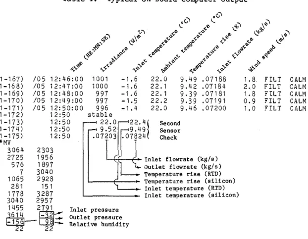
i n i t i a t e d manually by t h e o p e r a t o r . This command g i v e s t h e o p e r a t o r t h e o u t p u t s ( i n m i l l i v o l t s ) of every channel. Three of t h e s e r e a d i n g s a r e used l a t e r .T y p i c a l l y d u r i n g a c l e a r day t h e c o l l e c t o r i s t e s t e d a t one f l o w r a t e and t h r e e o r f o u r (depending on t h e d a y ' s l e n g t h ) i n l e t t e m p e r a t u r e s . Table 1 g i v e s a n example of a t y p i c a l on-board computer o u t p u t . Lines a r e
p r i n t e d i n memory every 60 seconds. They r e p r e s e n t t h e e x p o n e n t i a l average* of r e a d i n g s t a k e n e v e r y 5 seconds.
A f t e r s t a b i l i t y h a s been achieved a Second Sensor check i s executed and t h e r e s u l t p r i n t e d i n computer memory ( a g a i n t h e s e numbers a r e e x p o n e n t i a l a v e r a g e s ) . Then t h e
MV
command i s executed and t h e i n s t a n t a n e o u s m i l l i v o l t o u t p u t s of e v e r y channel a r e p r i n t e d . Measurement of l o n g wave r a d i a t i o n ( o r more p r e c i s e l y T ) was done, every minute, by a s k y independent HPsky
41-CV based d a t a a c q u i s i t i o n system. The beam component of s o l a r r a d i a t i o n was measured and recorded e v e r y minute by D B R ' s l i q u i d c o l l e c t o r c a l o r i m e t e r d a t a a c q u i s i t i o n system.
3 . 2 Data Reduction
A t t h e end of t h e a l l t h e raw d a t a , i s s u e d from t h e on-board computer, a r e t r a n s f e r r e d t o
a
DEC PDP 1 1 / 2 3 computer. Then a computer program t r a n s f o r m s a l l t h e raw d a t a i n t o a format compatible w i t h t h e e x i s t i n g DBR l i q u i d c a l o r i m e t e r d a t a p r o c e s s i n g software. B r i e f l y , t h e t r a n s f o r m a t i o n goes a s f o l l o w s :1. The raw d a t a f i l e i s scanned and t h e " s t a b l e " d a t a p o i n t s l o c a t e d . 2. The i r r a d i a n c e , ambient t e m p e r a t u r e , i n l e t t e m p e r a t u r e , temperature
r i s e , i n l e t f l o w r a t e and wind speed a r e averaged o v e r t h e l a s t f i v e minutes p r i o r t o t h e s t a b l e message.
3. The o u t l e t f l o w r a t e i s " e x t r a c t e d " from t h e second s e n s o r check. 4. The averaged t e m p e r a t u r e rise a c r o s s t h e c o l l e c t o r i s c o r r e c t e d f o r
header h e a t l o s s e s .
5. The i n l e t and o u t l e t p r e s s u r e s and t h e r e l a t i v e humidity a r e converted from t h e i r m i l l i v o l t o u t p u t t o e n g i n e e r i n g u n i t s u s i n g t h e a p p r o p r i a t e c o n v e r s i o n f a c t o r s .
6. Measurements of T and beam r a d i a t i o n a r e manually merged i n t o t h e transformed f i l e . sky
3 . 3 Data P r o c e s s i n g
The d a t a p r o c e s s i n g s o f t w a r e t a k e s a transformed f i l e and c a l c u l a t e s v a l u e s of t h e r m a l e f f i c i e n c y (I)) and (Ti
-
Ta)/G. The e f f i c i e n c y may be c a l c u l a t e d f i v e d i f f e r e n t ways (1,7):a ) E f f i c i e n c y based on a n e n t h a l p y balance:
"Exponential averaging:
11
a v e r a g e measurement a t t = 6 0 sec. = - ( a v e r a g e measurement a t t= 55 sec.)
1 1 2
+
-
( i n s t a n t a n e o u s r e a d i n g a t t=60 sec.). Exponential a v e r a g i n g i s used 12where, TL = (Ti
+
To)/2where, TL = (Ti
+
T0)/2is estimated by the experimenter
(1).
b) Efficiency based on the inlet flowrate:c) Efficiency based on the outlet flowrate:
In these equations the specific heat, Cp, is evaluated using the following algorithm:
C~
= 11030.1-
0.19762 T+
3.947 x 10⁻⁴ T2] +(1
1'792
+ W) ')Values of q vs (Ti
-
Ta)/G can then be plotted.A
typical output is presented in Figure5,
where the same data have been plotted three different ways.
4.0
CalibrationCalibration of such a facility is essential to ensure experimental accuracy. In actual fact, an earlier calibration (8) proved to be important as severe inaccuracies were detected. In what follows the measurements have been divided into two categories, critical or non-critical, depending on whether they have a direct or a second order effect on thermal efficiency. 4.1 Calibration of the non-critical measurements
4.1.1 Orifice plate air temperature sensors
Both orifice plate air temperature sensors were calibrated in a
temperature bath against a precision platinum resistance temperature sensor that had been calibrated by the Division of Physics of the NRCC. Spot
checks were made at O°C and 80°C. In every case the sensors were within the accuracy requirement set fosward by ASHRAE Standard 93-77 ( 3 ) ,
i.e. f0.5'C).
4.1.2 Wind speed measurement
The manufacturer accuracy claim (fO.l m/s or 1%) for the wind
measurement was deemed sufficient with respect to the ASHRAE Standard 93-77 requirement (f0.8 m/s), therefore, the wind sensor was not calibrated. 4.1.3 Long wave and normal incidence radiation
The pyrgeometer and the
NIP
were calibrated by Atmospheric Environment Services (AES) in Toronto; no accuracy claims are given with thesecalibration certificates.
4.1.4
Humidity sensorThe humidity sensor was calibrated by immersing it in saturated salt solutions as recommended by the manufacturer. The results indicate that in the range 0%-75%
RH
the accuracy is f2-3%RH,
while from 75% to 100% the accuracy is 25%RH.
4.1.5 Pressure sensors
Calibration of both orifice plate differentials pressure transducers showed that their outputs were within 21% of the readings given by a Betz manometer (manufacturer accuracy
-
f 0.01 "H20).The barometer used to calculate the barometric pressure was not calibrated as it is a fundamental measurement in itself. The digital
micromanometers, used for the measurement of inlet and outlet pressure, were calibrated against a Betz manometer and shown to give readings accurate to f2% in their range of operation.
4.2 Calibration of the critical measurements
Referring back to Eqns. 1-5, one can see that the measurements of mass flowrate, differential temperature, global irradiance, collector area, air specific heat, ambient temperature and inlet temperature are all critical for an accurate determination of I).
4.2.1 Global solar irradiance
The PSP used to measure global irradiance was calibrated at AES where calibrations are provided to within +3% of the World Radiation Reference (9).
4.2.2 Collector area
The accuracy of the aperture area measurement, i.e. the area of the collector through which solar radiation is admitted, is typically of the order of +0005 m2 (based on random uncertainty of 3 mm on length and width measurements.
4.2.3 A i r s p e c i f i c h e a t
It is e s t i m a t e d t h a t f o r t h e temperatures and humidity r a t i o s normally encountered t h e accuracy of t h e a i r s p e c i f i c h e a t , C is +0.1%.
P 4.2.4 Ambient t e m p e r a t u r e
The ambient t e m p e r a t u r e s e n s o r was c a l i b r a t e d a l o n g w i t h t h e o r i f i c e p l a t e a i r t e m p e r a t u r e s e n s o r s and showed t h e same accuracy (i.e. 20.5"C). 4.2.5 I n l e t and o u t l e t t e m p e r a t u r e s
Because t h e t e m p e r a t u r e s e n s o r s c o u l d n ' t be immersed i n a t e m p e r a t u r e b a t h , c a l i b r a t i o n of t h e i n l e t and o u t l e t t e m p e r a t u r e s e n s o r s had t o be c a r r i e d o u t t h e f o l l o w i n g way: The i n l e t and o u t l e t temperacure measuring s e c t i o n s were p u t end t o end and i n s u l a t e d ( w i t h approx. 300 mm of
f i b e r g l a s s i n s u l a t i o n ) . A c a l i b r a t e d platinum r e s i s t a n c e t e m p e r a t u r e s e n s o r was i n s e r t e d i n between t h e two s e c t i o n s and t h e f l o w r a t e was s e t t o 0.10 k g / s . I n t h i s way t h e o u t p u t of t h e i n l e t and o u t l e t t e m p e r a t u r e s e n s o r c o u l d be checked a g a i n s t t h e c a l i b r a t e d s e n s o r . R e s u l t s of t h e c a l i b r a t i o n a r e p r e s e n t e d i n Table 2.
It can be s e e n t h a t t h e primary and secondary s e n s o r r e a d i n g s a r e w i t h i n t h e ASHRAE (3) accuracy envelope of f0.5'C.
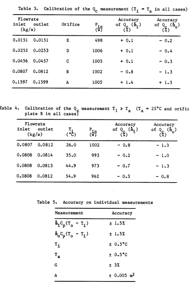
4.2.6 Mass f l o w r a t e and d i f f e r e n t i a l t e m p e r a t u r e measurements
The secondary measurements needed i n t h e d e t e r m i n a t i o n of t h e mass f l o w r a t e , i.e. t h e b a r o m e t r i c p r e s s u r e , t h e o r i f i c e p l a t e a i r t e m p e r a t u r e s , t h e d i f f e r e n t i a l p r e s s u r e and t h e humidity measurements were a l l c a l i b r a t e d ( s e e above).
C a l i b r a t i o n of t h e
&
measurement p e r s e , which would i n c l u d e t h e e r r o r s i n t h e secondary measurements a s w e l l a s e r r o r s i n h e r e n t t o t h e d e s i g n of t h e o r i f i c e p l a t e , was n o t undertaken due t o t h e d i f f i c u l t y i n f i n d i n g a good f l o w r a t e measurement a g a i n s t which b o t h5
c o u l d be c a l i b r a t e d . Also, a s mentioned above, t h e d i f f e r e n t i a l t e m p e r a t u r e measurement could n o t be c a l i b r a t e d i n d i v i d u a l l y . For t h e s e two r e a s o n s a n o v e r a l l c a l i b r a t i o n of t h e Qc measurement (which i n c l u d e s t h e measurement e r r o r on&,
C and on AT)was performed. P
B r i e f l y , i n t h e o v e r a l l c a l i b r a t i o n approach
(a),
t h e s o l a r c o l l e c t o r i s r e p l a c e d w i t h a C a l i b r a t i o n Heat Source (CHS) ( l o ) , which t r a n s f e r s a n a c c u r a t e l y measured q u a n t i t y of e l e c t r i c a l e n e r g y , Pin, t o t h e c i r c u l a t i n g f l u i d ( a i r ) . Assuming z e r o leakage* i n t h e CHS, and knowing t h a t t h e amount of energy c o l l e c t e d , Qc, can be expressed as:*A s t a t i c leakage t e s t was performed on t h e CHS and t h e leakage r a t e was found t o be 5 x 10⁻⁵ k g / s @ -1000 Pa of p r e s s u r e , t h u s l e a k a g e i s
The accuracy can the be determined by comparing Qc as measured by the test loop (including it's software processing), with the known power input Pi,. Calibrations were performed on all five orifice plates with the inlet
temperature equal to the ambient temperature (Table
3)
and with one orifice plate (orifice plateB)
at Ti>
Ta (Table4).
The accuracy of Qc is defined as:It is relatively safe to say, based on these results that the accuracy on the Qc measurement is
+1.5%.
Table 5 summarizes the calibration results of the critical
measurements.
A
detailed uncertainty analysis of air solar collector test results is presented in (1).5.0
ConclusionThis paper described the experimental test facility used to test air solar collectors at the NRCC. Results of a thorough calibration of the facility indicates that the amount of energy collected can be measured to an accuracy of
+1.5%
in the range of flowrates and temperatures normallyencountered in air collector testing.
Acknowledgement
The author would like to express his graritude to
Mr.
L.P. Chabot who helped in modifying and calibrating the facility.References
1.
Bernier, M.A., Plett, E.G., On Thermal Performance Representation and
Testing of Air Solar Collectors. In preparation.
2. Outdoor Solar Collector Test Eauiument at the National Solar Test
- -
Facility, Ontario Research Foundation, Report No. PHYS. G.P. 81-15,
198
1.
3. Methods of Testing to Determine the Thermal Performance of Solar
Collectors, American Society for Heating, Refrigerating and
Air-Conditioning Engineers, ASHRAE Standard 93-77, 1977.
4. Fluid Meters, Their Theory and Application, American Society of
Mechanical Engineers, Fifth Edition, New York, 1959.
5. Measurements of Fluid Flow by Means of Orifices Plates, Nozzles and
Venturi Tubes Inserted in Circular Cross-Section Conduits Running Full,
IS0 Standard 5167-1980(E), IS0 Standards Handbook 14, 1983.
6.
Bernier, M.A., Correcting for Header Heat Losses when Testing Solar
Collectrors, ISES World Congress, Montreal, June 1985.
7.
Bernier, M.A.,
Thermal Performance Representation and Testing of Air
Solar Collectors, M.Eng. Thesis, Carleton University, Ottawa, 1985.
8.
Bernier, M.A.,
NRCC Air Collector Test Facility, First EC conference on
Solar Heating, Amsterdam, Netherlands, 1984, pp. 499-503.
9.
Hay, J.E., Wardle, D.I.,
An Assessment of the Uncertainty in
Measurements of Solar Radiation, Solar Energy, Vol. 29, No. 4, 1982,
pp. 271-278.
10. Wright, J.L., Hollands K.G.T.,
A Calibration Collector for Solar Air
Heater Test Loops, University of Waterloo Research Institute, Final
Report for DSS contract 07SU.31155-0-2605, Waterloo, 1980.
11. Sodec, F., Moog, W., Influence of Friction on the temperature of a
flowing gas, Ki (Klima-und Kaelteingenieur) 1(7),
23-26, 1973.
(Translated from German to English by the Canadian Institute for
Scientific and Technical Information).
12. Procedure for determining Heat and Cooling Loads for Computerizing
Energy Calculations
-
Algorithms for building heat transfer
Table 1 . Typical on-board computer output
1-167) / 0 5 1 2 : 4 6 : 0 0 1 0 0 1 - 1 . 6 22.0 9.49 .07188 1.8 F I L T CALM 1 - 1 6 8 ) /05 1 2 : 4 7 : 0 0 1000 - 1 . 6 22.1 9 . 4 2 .07184 2.0 F I L T CALM 1-169) / 0 5 12:48:00 99'7 -1.6 2 2 . 1 9 . 3 9 . 0 7 1 8 1 1.8 F I L T CALM 1 - 1 7 0 ) /05 1 2 : 4 9 : 0 0 997 -1.5 2 2 . 2 9.39 . 0 7 1 9 1 0.9 F I L T CALM
Table 2. Calibration of the i n l e t and o u t l e t temperature sensors
T1 To
( c a l i b r a t e d Primary Secondary Primary Secondary
Table
3.Calibration of the
Q,measurement (Ti
=T, in all cases)
Flowrate
Accuracy
Accuracy
inlet
outlet
Orif
ice
of
Q
($1
of
Q
(in,)
(kgls)
(2)
(2)
Table
4.
Calibration of the
Q
measurement T1
>
Ta
(Ta
= 2S°Cand orifice
plate B in all casesf
Flowrate
Accuracv
Accuracv
inlet
outlet
of
Q
($)
(kg/s)
(2)
Table
5 .Accuracy on individual measurements
- -
a) A z i m u t h d r i v e b ) A l t i t u d e d r i v e
(a,
I
C) Inlet h e a d e r (uninsulated) d ) I n l e t h e a d e r (insulated)
e) I n s t r u m e n t a t i o n b o x f) R e m o t e c o n t r o l o p e r a t i o n
test facility
-
SECTION A-A
Figure
4.
Temperature measuring sectionEFFICIENCY BASED O N THE
EFFICIENCY BASED O N A N ENTHALPY BALANCE
AT < O I N
FFlClENCY BASED O N THE
( T i - T a ) l G ( M " " 2 " D E G . C I W )
APPENDIX A
The Measurement of Air Mass Flowrate Using Orifice Plates 1.0 Principle of the method
A primary device, the orifice plate, is inserted in a pipe in which a fluid is running full. The static pressure difference created by the introduction of the primary device is measured by secondary devices
(manometer, pressure transducer) and the AIR mass flowrate can be determined according to the following equation (in S.I. Units):
s = c * E
y
* A t [ 2 * A P'2
where,is the air mass flowrate (kg/s)
C
is the discharge coefficient (dimensionless):E is the velocity of approach factor (dimensionless):
y
is the gas expansion factor (dimensionless), for orifice plates:At is the orifice area (m2)
AP is the differential pressure across the orifice (Pa)
p1 is the air density in the plane of the upstream pressure taps (kg/m3). For an airwater vapor mixture,
pl
may be expressed as:P1 (1 + W)
p1
= 0.0034858 (for P1 near atmospheric pressure) T1 (1+
1.608 W)P1 is the absolute pressure at the upstream pressure taps (Pa)
T1 is the absolute temperature in the plane of the upstream pressure taps,
K
W is the humidity ratio, kg H20/kg dry air
Re is the Reynolds Number (dimensionless)
is the air viscosity (~*s/rn~)
k is the isentropic coefficient (k-1.4 for air)
p
= d/Dd is the orifice diameter (m)
2.0 Note on the evaluation of C
The discharge coefficient, C, is a function of
rfi,
the mass flowrate. The mass flowrate being unknown at the start, an interative process has to cake place: A flowrate is guessed and an estimate ofC
obtained, with this estimate of C a newrfi
is calculated and the process is repeated untilconvergence is obtained (usually
3-4
iterations).3.0
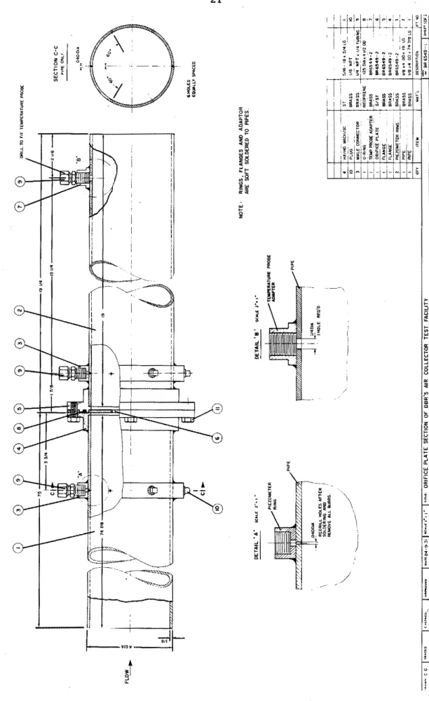
Construction detailsThe two identical orifice plate sections were built according to IS0 and ASME (4,5) specifications (Figs. A1 and A2). The orifice plate sections are made of brass as it was the only material meeting the circularity and roughness of pipe requirements. The orifice plates are made of
stainless-steel. The tolerances set forward in
(5)
for the perpendicularity of the orifice plate, the pressure tapping arrangement and the required straight length of pipe before and after the plates were all surpassed. After construction, both orifice plate sections were sealed at both ends and pressurized to approximately 35 kPa; no leaks were detected.4.0
AP, p, (PI ,TI,
W) measurementsThe static pressure drop across the orifice, AP, is measured using a variable reluctance pressure transducer. The determination of the density.
"1, requires the measurement of P1, T1, W. The absolute pressure at the
upstream pressure tap, PI, is obtained by subtracting from the local barometric pressure measurement the pressure difference, as measured by a digital micromanometer, from ambient to the upstream pressure tap. The air temperature, TI, is measured using five elements silicon temperature
sensors, located 530 mm downstream from the upstream pressure taps. The humidity ratio, W, is obtained from the relative humidity (section 2.6) and ambient temperature measurements (section 2.2.2) using the algorithm