HAL Id: tel-01693147
https://tel.archives-ouvertes.fr/tel-01693147
Submitted on 25 Jan 2018HAL is a multi-disciplinary open access
archive for the deposit and dissemination of sci-entific research documents, whether they are pub-lished or not. The documents may come from teaching and research institutions in France or abroad, or from public or private research centers.
L’archive ouverte pluridisciplinaire HAL, est destinée au dépôt et à la diffusion de documents scientifiques de niveau recherche, publiés ou non, émanant des établissements d’enseignement et de recherche français ou étrangers, des laboratoires publics ou privés.
Novel photocatalytic TiO2-based porous membranes
prepared by plasma-enhanced chemical vapor deposition
(PECVD) for organic pollutant degradation in water
Ming Zhou
To cite this version:
Ming Zhou. Novel photocatalytic TiO2-based porous membranes prepared by plasma-enhanced chem-ical vapor deposition (PECVD) for organic pollutant degradation in water. Material chemistry. Uni-versité Montpellier, 2015. English. �NNT : 2015MONTS090�. �tel-01693147�
1
THESIS
To obtain the grade of
Doctor
Issued by
University of Montpellier
University of Chemistry and Technology, Prague University of Calabria
Prepared in the graduate school Sciences Chimiques Balard (ED 459)
And research Unit
Institut Européen des Membranes IEM (UMR 5635)
Speciality:
Chemistry and Physico-chemistry of Materials
Presented by MING ZHOU
Defended on 23 July 2015 in front of the esteemed jury comprising
Mr. Zoltán HÓRVÖLGYI, Professor, BME Budapest Reviewer Mr. Petr ŠPATENKA, Professor, Czech Technical Univ. Prague Reviewer Mr. Jean-Christophe REMIGY, Assistant Professor, UPS Toulouse Reviewer Mr. Efrem CURCIO, Professor, University of Calabria Examiner Mr. Vasile HULEA, Professor, ENSCM Montpellier Examiner,
President of the jury
Mrs. Enrica FONTANANOVA, Research Scientist ITM-CNR Rende Thesis co-director Mr. Vlastimil FILA, Assistant Professor, UCTP Prague Thesis co-director Mr. André AYRAL, Professor, Univ. Montpellier Thesis co-director Mrs. Stéphanie ROUALDES, Assitant Professor, Univ. Montpellier Thesis director
NOVEL PHOTOCATALYTIC
TiO
2-BASED POROUS MEMBRANES
PREPARED BY PLASMA-ENHANCED
CHEMICAL VAPOR DEPOSITION
(PECVD) FOR ORGANIC POLLUTANT
DEGRADATION IN WATER
TREATMENT TECHNOLOGY
3
Outline
Acknowledgements……….…………..….. 6
Introduction ………..…..7
Chapter I Bibliography fundamentals……….... 13
1 Photocatalytic titanium dioxide (TiO2) membrane for wastewater treatment…..…13
1.1 Photocatalysis process……….13
1.1.1 Band gap energy of semiconductor………..13
1.1.2 Mechanisms in semiconductor photocatalysis………...…..18
1.2 TiO2 as photocatalytic material………...………23
1.2.1 Historical overview and up-to-date applications of TiO2………….……24
1.2.2 Crystal phase, surface reactions and band gap of TiO2……….…...27
1.3 TiO2 photocatalytic membrane reactors (PMRs)……….…35
1.3.1 Advanced oxidation processes (AOPs) for degrading pollutants….……35
1.3.2 Membrane separation integrated with photocatalytic AOP treatment…..38
1.3.3 TiO2 membranes………..……….….43
1.3.4 Reaction kinetics……….…………..54
1.4 Conclusion……….……….…….59
2 Plasma-Enhanced Chemical Vapor Deposition (PECVD) for TiO2 membrane manufacture………..….60
2.1 Generalities on PECVD process………..60
2.1.1 Chemical Vapor Deposition (CVD) methods………...……60
2.1.2 PECVD: a low temperature approach………...62
2.2 PECVD process for the preparation of TiO2 films………..…69
2.2.1 Deposition of inorganic film……….69
2.2.2 State-of-the-art on TiO2 films……….…………..73
2.3 Conclusion………..……….…79
Chapter II Experimental details………..….85
1 Preparation of supported TiO2 thin films……….….…85
1.1 Deposition of films by PECVD method……….……...…..85
1.1.1 PECVD set-up……….….…85
1.1.2 Precursor and substrates………...……88
1.1.3 Plasma deposition protocol and operating conditions………..91
4
1.2.1 Post-annealing as a function of temperature 300 – 700 °C…….……….98
1.2.2 Post-annealing as a function of duration at 300 °C………..99
1.3 Seeding approach prior to PECVD process………99
1.3.1 Seeding substrate by sol dip-coating………...………100
1.3.2 PECVD TiO2 deposition on the seeded substrate………101
2 Characterization on physico-chemical properties of TiO2 films………..101
2.1 Morphology, chemistry, surface wettability and crystal structure (FTIR, EDX, SEM, WCA, XRD and Raman)………..102
2.2 Porosity and band gap energy (XRR, EP and UV/Vis)………..104
2.3 Investigation on phase transformation from amorphous TiO2 to anatase (TGA-DSC and HT-XRD)………...….106
3 Characterization on functional properties of TiO2 films……….…107
3.1 Photocatalytic activity measurement in “static“ condition………108
3.1.1 Model compound, supported TiO2 film and UV lamp………108
3.1.2 Pilkington test……….109
3.2 Photocatalytic activity measurement in “dynamic“ condition…….………..111
3.2.1 Model compound, TiO2-coated membrane, diffusion cell, UV lamp….111 3.2.2 Diffusion test………..112
3.3 Materials and method for membrane performance in photocatalytic membrane reactor (PMR)………115
3.3.1 Lab-scale PMR (at ITM-UNICAL)………115
3.3.2 Pilot-scale PMR (at IEM-UM)………...……120
Chapter III Physico-chemical properties of TiO2 material………..…………125
1 Optimization of PECVD operating conditions………..………..125
1.1 Effect of substrate temperature (Ts)………...…125
1.2 Influence of partial pressure (PAr+TTIP) and plasma distance (dp)…..……….130
1.2.1 Effect on thickness homogeneity and deposition rate……….……..130
1.2.2 Effect on Ti-O abundance per unit volume in the film………..133
1.3 Effect of electric RF power………135
2 Optimization of post-annealing conditions to develop crystallized films…….…..139
2.1 Film crystallization as a function of temperature (Tp)…………..…………..139
2.2 Film crystallization as a function of heating duration (tp)……….142
5
3 Structural property of the optimal TiO2 anatase thin film………...148
3.1 Morphology, crystal structure and photo-induced hydrophilicity………….148
3.2 Band gap energy (Eg)……….152
3.2.1 UV/Vis spectroscopy analysis on Eg……….152
3.2.2 Ellipsometry spectroscopy analysis on Eg………157
3.3 Porosity……….159
4 Conclusion……….……….161
Chapter IV Photocatalytic and permeation properties of TiO2 material……..….163
1 Photocatalytic activity of PECVD TiO2 thin film (on silicon) in static condition..163
1.1 Effect of PECVD substrate temperature………164
1.2 Effect of post-annealing temperature……….165
2 Photocatalytic activity of PECVD TiO2 thin film (on alumina) in diffusion condition………..167
2.1 Morphology and catalytic efficiency of TiO2-layer coating (M100)……….168
2.2 Morphology and catalytic efficiency of TiO2-skin coating (M800)………...172
3 Photocatalytic and permeation properties of PECVD TiO2-based membrane in dynamic condition………....176
3.1 Configuration of photo-active TiO2 toward permeate (Pilot-scale unit)……176
3.2 Configuration of photo-active TiO2 toward feed (Lab-scale unit)………….180
3.2.1 Acid orange 7 as degraded model compound………..……..180
3.2.2 Phenol as degraded model compound………...………187
4 Mathematical modeling of sorption and photoreaction processes…….…………..190
4.1 Modeling of organic solute sorption by TiO2-based membrane………190
4.1.1 Mathematical descriptions………...………..190
4.1.2 Results of sorption modelling………..………..193
4.2 Modeling of photodegradation by illuminated TiO2-based membrane……..201
4.2.1 Mathematical descriptions………...………..201
4.2.2 Results of reaction modelling of AO7 decomposition….……….209
5 Conclusion………...………....212
General conclusion and perspectives………..……215
Appendices………..……..219
References………...221
6
Acknowledgements
The Doctorate of Ming ZHOU has been completed at the European Institute of Membranes (IEM) and carried out in three Universities: University of Montpellier (France), University of Chemistry and Technology, Prague (Czech Republic) and University of Calabria, Rende (Italy). It was financed by the scholarship of European Commission - Education, Audiovisual and Culture Executive Agency (EACEA) under the program “Erasmus Mundus Doctorate in Membrane Engineering” (EUDIME, FPA No. 2011-0014, Edition I, http://eudime.unical.it). Ming ZHOU would like to thank the main contributors to this work:
The three reviewers:
Mr. Zoltán HÓRVÖLGYI, Professor, BME Budapest
Mr. Petr ŠPATENKA, Professor, Czech Technical Univ. Prague Mr. Jean-Christophe REMIGY, Assistant Professor, UPS Toulouse The examiners:
Mr. Efrem CURCIO, Professor, University of Calabria Mr. Vasile HULEA, Professor, ENSCM Montpellier The supervisors:
Stéphanie Roualdès1, André Ayral1, Vlastimil Fila2, Josef Krysa2, Enrica Fontananova3, Teresa Poerio3, Enrico Drioli3
1
Institut European of Membranes (IEM), University of Montpellier, France
2
University of Chemistry and Technology, Prague (UCTP), Czech Republic
3
7
Introduction
Wastewater source is consisting of industrial, municipal and agricultural water discharges. Globally there is about 171 km3 of wastewater produced annually including liquid releases from homes, businesses, industries and storm water run-off. [1] Each year from 40% to 60% of energy consumption has been utilized for operations and maintenances in treating wastewater and the total expense of power used for wastewater treatment is $10 billion a year on the earth. [1] Industry processes including paper manufacture, dyeing, painting, coaling and mining have employed a great amount of water due to washing, mixing and cooling. Removal of toxic organic contaminants (e.g. alkanes, alcohols, haloalkanes and aromatics) from high-level contaminant wastewater before discharging is supervised by environmental legalization. On the other hand, reusing the low-level wastewater (from municipal and rural discharges) for agricultural and industrial purposes is one appealing strategy to offset the clean water distributions. However, the presence of organic pollutants keeps arising in the releases from households, hospitals and rural areas due to increasing consumption of chemicals. Efficient and less costly treating process for sorts of discharged water is required today.
In typical wastewater treatment (WWT) routine, physical, chemical and biological approaches are accordingly performed. Adsorption and coagulation procedures are first operated to remove solids and large particles from water. Filtration, sedimentation and membrane separation could concentrate soluble pollutants into another phase but with no degradation consequence. Oxidation and decomposition of tedious contaminants can be carried out through chemical and/or biological pathways, however, sometimes the chemical process can possibly bring additives and/or by-products as a secondary pollution to the water. A conception of advanced oxidation processes (AOPs) was stated by Glaze and et al. in 1987 [2], which lead to a rapid development in the field as innovative water treatment technology. Oxidation processes are carried out through in-situ hydroxyl radical •OH having high oxidation potential as E0 (•OHaq/H2O) = 2.59 V at pH=0. [3] Some other strong reactive
oxygen species (ROSs) such as •O2–, O3 and H2O2 might be also involved in the processes.
AOPs are particularly effective in eliminating stubborn pollutants as dyes, surfactants, pharmaceuticals, pesticides, herbicides and petroleum constituents in water. Nowadays, most of AOP facilities are built in Europe and USA due to a high expense of conventional AOP procedures working with costly oxidant reagents for instance H2O2 and O3 in order to produce
8 •
OH. For a large volume of wastewater to be treated, a large amount of the oxidant reagents is demanded in an AOP plant.
Photocatalyzed AOP system consisting of TiO2/UV/O2 has been developed since illuminated
TiO2 was found as a photocatalytic electrode in water splitting experiment made by Fujishima
and Honda in 1972. [4] A common mechanism is described as •OH radical is generated by charge separation of !" and#$% on TiO2 by absorbing photo energy larger than the band gap
energy (Eg). [5] With the catalytic reactions, ambient O2 could replace the pricy oxidants such
as H2O2 and O3 in AOP operations. TiO2 photocatalyzed oxidation has been applied to deal
with numerous pollutants including degradation of organic contaminant in water [6, 7], deactivation of bacteria [8] and virus [9], and removal of inorganic substances as nitrides, sulfides and heavy metals [10]. Slurry reactor using dispersed TiO2 catalyst (e.g. Degussa P25
powder from Evonik: specific surface area 50 m2 g-1 and particle size 25 nm) in feed flow has very often been practiced in aqueous purification. However, filtrating the catalyst particles is the bottleneck to scale up to industrial application. [10] Moreover, TiO2 nanoparticles have a
tendency to aggregate due to large surface area.
Overall heterogeneous catalytic reaction includes steps as 1) in-diffusion, 2) intraparticle in-diffusion, 3) adsorption, 4) surface reactions, 5) desorption, 6) out-diffusion and 7) intraparticle out-diffusion. Catalytic rate limiting steps could be film diffusion control (steps 1 and 7), pore diffusion control (steps 2 and 6) and intrinsic reaction kinetics control (steps 3 and 5). For highly exo/endo-thermic reactions the heat transfer could also affect heterogeneous catalysis process (e.g. steam reforming) in addition to the mass transfer effects as mentioned previously. An active catalyst has typically good selectivity for products over by products, good stability at reaction conditions, good accessibility of reactants and products and presents adequate rates of reactions. A photocatalyst would also be photo-responsible, that is a photon excites a free electron and forms positive-charged holes both leading to redox reactions in catalytic route.
Photocatalytic membrane reactors (PMRs) integrate membrane separation and photodegradation for purifying water. Slurry reactors coupled with pressure-driven membrane separation was presented in Ollis’ review in 2003 [11] and then a design of functionalized photocatalytic membrane was contemplated in Mozia’s review in 2010. [12] Fabricated membranes as TiO2-ceramic composite [13, 14], TiO2-polymer composite [15] and pure TiO2
9
membrane coated with TiO2 showed higher catalytic efficiency than that of membrane
entrapped with TiO2 since photoactive surface could supply more active sites to reactants and
light. A membrane reactor is preferred to a slurry reactor in terms of higher compactness, better integrity and separation feasibility, yet manufacturing TiO2-composite or pure TiO2
membranes in large scale at low cost is the key step to realize PMR industrial application in wastewater remediation. Common methods to immobilize TiO2 on substrate include thermal
spray [17], sol-gel process [18], physical vapor deposition (PVD) [19], and chemical vapor deposition (CVD) [20]. Either depositing temperature (e.g. ≥ 450 °C in thermal spray, PVD and CVD) or annealing temperature (e.g. ≥ 500 °C after sol dip-coating) is required as high as to prepare TiO2 anatase (the crystal phase considered as the most photoactive) according to
the literature.
Plasma-enhanced chemical vapor deposition (PECVD) can facilitate deposition of thin films at low temperature with the aid of thermal/plasma decomposition of precursor [21], making it potentially compatible to many types of membrane support (thermal-sensitive polymeric ones in particular). PECVD is capable of growing and tuning microstructure of TiO2 coating in
terms of particle size, porosity and thickness that could have noticeable impacts on the photocatalytic performance regarding to quantum size effect [22], surface area [23] and mass/light transfer [24]. Huang and et al. reported a minimal substrate temperature Ts = 450
°C in PECVD process is needed for in-situ formation of anatase TiO2 on silicon from
precursor TTIP with power equal to 100 W in 2002 [25, 26]. Wu and et al. deposited amorphous TiO2 layer on silicon performing PECVD at Ts = 200 °C and power 100 W from
TTIP and obtained crystalline anatase by post-annealing at 400 °C [26]. Lastly some groups have applied bias voltage (from -50 V to -150 V) in PECVD chamber and prepared anatase on silicon at Ts less than 150 °C using the same precursor [27, 28]. Yet the bias voltage may
damage substrate surface with strong ion bombardment and/or consecutive local increase of temperature and it is impossible to maintain the bias voltage on insulating polymeric materials [29, 30]. The “hard” conditions as high substrate temperature (450 °C) and/or high bias voltage (-150 V) are not suitable for membrane supports that are thermal-sensitive, less inert and insulate. Regarding to PECVD TiO2 thin films, no lower post-heating temperature less
than 400 °C has ever been reported before our group’s work published on anatase formation in PECVD process at Ts = 150 °C and post-heating at 300 °C for 5 h in 2015 [31].
10
The ojective of the thesis is to fabricate porous nano-structured photocatalytic membrane (for instance TiO2-ceramic composite membrane) for degrading organic impurities in water.
Photocatalysis (a heterogenous catalytic process) coupled with membrane process as an integration operation is interested for its feasibility of separation and compactness. A thin film of TiO2 will be deposited on mechanical support with plasma-enhanced chemical vapor
deposition (PECVD) method. So that TiO2-coated membranes can be prepared and
photocatalytic function will be examined accordingly. The fabricated photocatalytic TiO2-composite membrane is in fact a functionalized porous ceramic membrane with a TiO2
thin film deposited on top of it. TiO2 coating layers would be deposited in PECVD process
from working gases of TTIP + Ar + O2 possibly followed with a post-annealing step for
crystallization. Effect of PECVD operating parameters (including substrate temperature, partial pressure, plasma distance and RF power) on physico-chemical properties of silicon-supported TiO2 thin films have been first studied. Deposition rate, thickness
homogeneity, Ti-O abundance in the film, crystal structure and band gap energy can be reflected from SEM, FTIR, XRD, XRR and UV/Vis measurement. Minimal crystallization temperature in the post-thermal treatment would be found and reduced with substrate with seeding-effect. In the continuous work, alumina porous disks with top-layer pore size 100 nm and 800 nm are supplied as the substrates for TiO2-layer coating (membrane type M100: TiO2
thickness > 10 times of support pore size) and TiO2-skin coating (membrane type M800: TiO2
thickness < 0.5 times of pore size) respectively. Photodegradation efficiency of organic solutes in water by the illuminated M100 and M800 membranes are examined in lab-scale and pilot-scale membrane reactors built at two institutes IEM-UM (France) and ITM-UNICAL (Italy) in the partnership of the doctoral program. The established preparing procedure of TiO2-composite membrane with PECVD approach combined with post-annealing is wished to
be a solution to large-scale manufacturing TiO2-based water purifier for photocatalytic AOP
treatment on wastewater.
Structure of the thesis contains four chapters in total on bibliography fundamentals, experimental details, physico-chemical properties and functional performance of the synthesized materials. The literature review (chapter I) is focused on mechanisms of photocatalysis process and up-to-date application and preparation of TiO2 materials. The
experimental part (chapter II) describes the applied low-temperature PECVD technique to produce supported TiO2 thin films, followed with information of characterization instrument
11
dedicated for physico-chemical properties of optimal PECVD TiO2 thin films. Properties of
TiO2 thin film including morphology, nanocrystal structure, density (or porosity), surface
hydrophilicity and band gap energy (Eg) are analyzed and presented in this third chapter.
Lastly, chapter IV is for functional performance of PECVD TiO2-coated ceramic membrane.
Photodegrading efficiency of aqueous organic pollutant by the illuminated TiO2/Al2O3
composite membrane (Photodegradation tests have been made in both concentration-driven and pressure-driven membrane processes) and the mathematical modeling of photoreactions are discussed in this fourth chapter. Lastly, a general conclusion of the Ph.D. work and perspectives for future research interest are given in the end of the thesis.
13
Chapter I Bibliography fundamentals
The literature review in this chapter focuses on two fields: photocatalytic TiO2 membrane for
environment remediation and the common preparing methods for TiO2-based membranes.
The first part is extended into photocatalysis mechanism, properties of TiO2 and
photocatalytic membrane reactors (PMRs). The second part is started with general principles of chemical vapor deposition (CVD) and plasma-enhanced chemical vapor deposition (PECVD) and followed with recent studies on TiO2 synthesis with PECVD approach.
1 Photocatalytic titanium dioxide (TiO2) membrane for wastewater treatment
Titanium dioxide (TiO2) is photocatalytic active by absorbing ultraviolet (UV) spectrum
(specifically the light energy of wavelength from 310 – 390 nm). Crystalline TiO2 (anatase
phase) is widely used as a photocatalyst due to its high catalytic efficiency, stability, bio-compatibility and inexpensive cost. Immobilized form of TiO2 (e.g. as composite
membrane) has attracted researchers’ attention on photocatalytic oxidation treating for organic pollution in wastewater. Photocatalysis mechanism, coupling photocatalytic oxidation and membrane process, properties and applications of TiO2 materials and explored
photocatalytic membrane reactors (PMRs) will be explained and discussed in this chapter. 1.1 Photocatalysis process
Photocatalysis is an acceleration of photoreactions in the presence of light and a catalyst. Photocatalytic oxidation is triggered by photo-generated hydroxyl radical (•OH) resulted from charge separation on photocatalyst (most often as semiconductors) when it is exposed to irradiation. Separated charge carriers include electron and positive hole, which diffuse in semiconductor and produce •OH radical by interacting with species such as water and oxygen. Produced •OH is a strong and non-selective oxidant that can dynamically oxidize many tedious organic molecules.
1.1.1 Band gap energy of semiconductor
Some inorganic materials such as semiconductor are found to be photocatalytic active. They can accelerate photoreactions for instance splitting the water molecules, oxidizing organic compounds and deactivating organisms. Photon energy is transferred to chemical activation energy leading to molecular decomposition. In order to understand photo-electronic processes on semiconductor particles, it is necessary to clarify band gap theory first.
14
Band gap is energy range in solids where electrons cannot exist, which is relevant of the electric conductivity of materials. It is the referred property to define metal, semiconductor and insulator. There is generally no band gap in metal conductors, but a large almost insurmountable gap (greater than 3 eV) in insulators. In semiconductors the gap is typically of intermediate value (at temperature below the melting point) in comparison with metallic and insulating solids. A schematic illustration of band gap in different materials is displayed in Figure 1-1[32].
Fig. 1-1 Band gap in different materials: metal, semiconductor and insulator. [32] Band gap indicates an energy difference between valence band and conduction band as in the electronic energy levels. The valence band (a “bonding” band) is filled with electrons that are strongly attracted by atomic nuclear and tied on molecular orbitals. In the conduction band (an “anti-bonding” band), electrons are not tightly confined since the nuclei’s attraction is getting weaker and they are free to flow with higher energy. In Figure 1-1 the highest occupied state in valence band (EVB) being filled with electrons is colored in red, and the
lowest unoccupied state in conduction band (ECB) devoid of electrons is colored in blue.
Accordingly, the band gap energy (Eg) is defined as in Equation 1-1:
&' = &(),*+-. &/),*01 (1-1)
where Eg is band gap energy, ECB,min is the minimal energy level in conduction band and EVB,max
is the maximum energy level in valence band.
Common semiconductors such as gallium arsenide (GaAs) and cadmium selenide (CdSe) have Eg less than 3 eV; others such as silicon carbide (SiC), titanium oxide (TiO2) and zinc
15
oxide (ZnO) have Eg value around 3 eV as shown in Figure 1-2. [33] SiC, TiO2 and ZnO are
considered as semiconductors with large band gap by the modern ceramists. [34] The gap defines the required photon energy to excite an electron from lower energy level to higher one. An electron in the semiconductor can undergo inter-band transition with irradiation power of at least its band gap energy. Consequently, a positive hole is created locally when the electron leaves its position. Then charge-carriers are separated and responsible for following redox reaction on illuminated semiconductor particles. [35]
Fig. 1-2 Energies for various semiconductors in aqueous electrolytes at pH=1. [33] Light of photon energy less than Eg will penetrate the semiconductor without separating the
charges. In contrast, photon energy larger than Eg will cause electronic transition and form
electron-hole pairs. The excessive energy can be dissipated through radiative and/or thermal (non-radiative) ways. Energy of the light (an electromagnetic wave) is described with its frequency as Planck-Einstein relation as given in Equation 1-2. Frequency (v) is a ratio of speed (c) over wavelength (λ) as v=c/λ, so that Planck-Einstein relation can be also expressed in Equation 1-3.
& = $2 (1-2) Or
16
where E is light energy, h is Planck constant (6.63×10⁻³⁴ J s), v is frequency, c is velocity of light (in vacuum) and λ is wavelength.
As mentioned previously, the energy threshold (E) of liberating an electron and forming a positive hole locally is at least equal to the band bap (Eg) as shown in Equation 1-4.
Combining it with Plank-Einstein relation (Equation 1-3), one can generally deduce which range of spectrum is capable to separate the charges depending on semiconductor’s band gap. An overall calculation on the compatible wavelength is obtained in Equation 1-5. Taking a semiconductor of band gap 3 eV as an example, light energy of wavelength shorter than 414 nm (in the UV band) is needed to form electron-hole pairs on the mentioned semiconductor. & 5 &' (1-4)
Hence, 6 7 $83
9 (1-5)
where E is light energy, Eg is band gap energy, h is Planck constant (6.63×10⁻³⁴ J s), c is
velocity of light in vacuum (3×10⁸ m s-1) and λ is wavelength.
There are always two types of existing band gaps: either direct or indirect. [36] The difference is depending on the momentum of the inter-band electronic transition. In fact, the top level of valence band and the bottom level of conduction band are not always in the same momentum vector. When the transition momentum is the same it is named as direct band gap; otherwise it is indirect one. The lattice momentum P for an electron in a crystal lattice is Pcrystal = ћk,
17
Energy diagrams (E-k diagrams) describe the band edges by plotting band energies (E) as a function of momentum vector (k) as in Figure 1-3. [37] In a direct band gap as shown in Figure 1-3(a), the highest state of valence band (VB) and the lowest state of conduction band (CB) occur at the same momentum value. In indirect situation as shown in Figure 1-3(b), the maximum energy level in VB exists at a different momentum to the minimum energy level in CB. In the second situation, thermal particle “phonon” (due to lattice vibration), in addition to the radiative “photon”, is involved in energy transferring between the system and the photocatalyst itself.
Fig. 1-3 E-k diagrams of direct (a) and indirect (b) band gap in semiconductor. [37] A photon has a momentum Pphoton = E/c, where E is energy of light and c is velocity of light.
According to Planck-Einstein relation as in Equation 1-3, momentum of the photon can be also written as P = h/λ = hσ, where h the Planck constant, λ the wavelength and σ the wavenumber. Taking account that h = 6.63×10⁻³⁴ J s and λ is in the magnitude of 10-7 m, an optical photon has a small value of momentum in the order of 10-8 J s m-1. As a result, a photon of energy equal to band gap (Eg) can separate the charges more easily in
semiconductor of direct band gap than that of indirect one. [36] The straightforward electron transition demands smaller momentum change cross the direct band gap. In the contrast, an
18
electron has to undergo a more significant momentum change in order to transit in the indirect gap. [37] Energy evolution in indirect gap is more complex including both radiation and vibration process. Consequently, the indirect process has a slower kinetics rate. With the same reason, charge recombination is also less efficient in the indirect band gap. [38] Longer lifetime of separated charges with slower recombination rate (e.g. with the indirect gap) is an advantage for photocatalysis process, which is going to be further discussed in the next session 1.1.2.
1.1.2 Mechanisms in semiconductor photocatalysis
A graphic illustration of photocatalysis process is presented in Figure 1-4, where the photoelectron (!") and photohole (#$%) are separated on the illuminated photocatalyst (i.e. semiconductor). By absorbing a photon of energy hv vaEg, an electron is excited from the
“bonding” orbital in VB to the “anti-bonding” orbital in CB. At the meantime, a positive hole is left over in-situ at VB. Separated charge-carriers would be diffusing, trapped, and/or recombining on the photocatalyst particle. [39] The liberated electron (!()" ) could react with electron acceptor (A) in reduction reaction; while the positive hole ($/)% ) could react with electron donor (D) in oxidation reaction. On the other hand, recombination of the charges is limiting the photoreaction efficiency. [38]
Fig. 1.4 Mechanism of photocatalysis process.
In aqueous circumstance, the photo-generated electron (!()" ) could reduce dissolved O2
molecule in water and form oxidant species such as superoxide ion radical (•O2 –
19
the simultaneously generated positive hole ($/)% ) could oxidize H2O molecule and form
hydroxyl radical (•OH). [40] Radical •OH as one of the strongest oxidizing species has an oxidizing potentia
l
E0 (•OHaq/H2O) = 2.59 V at pH=0. [3] It could oxidize almost all sorts oforganic molecules (sometimes also for inorganic species). Molecular oxidation caused by •OH radical attack is known as advanced oxidation process (AOP) [2], which will be further discussed in the session 1.3. Global photochemical reactions catalyzed by illuminated semiconductor in water (dissolved with ambient oxygen) are written as following:
hν → !()" + $/)% (1-6) O2 + !()" →•O2– (1-7)
H2O + $/)% →•OH + H+ (1-8)
Lifetime of the separated !()" and $/)% on semiconductor particle is crucial for the photocatalytic activity. Most of the charge carries recombine themselves sooner or later either in a radiative or non-radiative (by heat) way. Charge recombination will weaken formation of hydroxyl radicals (•OH) due to less detached charges. Tracing !()" and $/)% formation, transfer, capture and recombination has been studied with various time-resolved spectroscopy techniques and the results on their lifetimes are summarized in a review by Fujishima et al in 2008. [38] Trapped electrons and holes absorb light in the visible and near-infrared spectra [41, 42], whereas free electrons absorb in the infrared or microwave regions [43, 44]. Optical absorbance by the charge carriers has been recorded by means of transient absorption (TA) [41], transient diffuse reflectance (TDR) spectroscopies [45], as well as time-resolved microwave conductivity (TRMC) [43]. After all, !" and#$%#involved in photocatalysis process have been accurately measured in their different states. Conclusive timescale indication is illustrated in Figure 1-5 with collective results of studying TiO2 samples in
different forms of film and powder. [38] In general, photo-generated !" and#$% have experienced from femtosecond (10-15 s) as formation until microsecond (10-6 s) as recombination according to those studied samples.
20
Fig. 1-5 Time scales in photocatalysis. [38]
Charge formation of electron-hole pair starts from femtosecond (10-15 s) as photon being absorbed on photocatalyst. [38] Charge capture takes place just afterward. Photoelectron is trapped in less than 200 fs and photohole less than 150 fs [42]. Charge diffusion/transfer occurs in the order of picosecond (10-12 s). [46] Relaxation of positive hole could happen faster (
~
100 ps) than that of electrons (~ 500 ps) [52]. For a nanocrystalline TiO2 film,half-life of electron-hole recombination is found ca. 1 μs for a film dipped in N2-saturated
deuterated water excited by low-intensity laser pulse. [44] Charge recombination undergoes when charge-carriers “randomly” walk and meet the opposite one no matter in the trapped or free status described as in the following:
!":$;<: > $2#or#heat (1-9)
!?@": $:> $2#or#heat (1-10)
!": $% > #$2#or#heat (1-11)
Oxidation reaction induced by $?@% has begun in less than 2 μs when water is involved in the system, whereas oxidation would only begin within 80 μs when no H2O has been interacted
21
than ns) and reduction reaction of O2 caused by trapped electrons (in a few μs) are also
indicated in the time line of Figure 1-5.
Charge capture on semiconductor particle is an essential step for photocatalytic performance. It suppresses recombination and assists interfacial charge transfer leading to larger amount of “hot” !" and#$% could sustain in the solid material. In some electron paramagnetic resonance (EPR) study on illuminated TiO2 particles, trapped electrons have been found in the
form of Ti3+, at the meantime, O2 adsorption on surface has caused Ti3+ signal decayed. [47,
48] Trapped holes have been observed in more complex and deeply scavenged states. For instance, surface hydroxyl (Ti–•O–Ti–OH), surface oxygen radicals (Ti–O–Ti–•O) and lattice oxygen radical ion (•O–) are proposed as the sites where positive holes could be confined. [47, 48] In other studies, two types of surface hydroxyl groups as Ti4+–•OH radicals (hole trapping) and Ti3+–OH groups (electron trapping) have been investigated both by experiments and theoretical calculations. [49] A density functional theory (DFT) study on hydroxylated TiO2
surface demonstrated an electron-trapping nature of Ti–OH bridges on crystal faces. [50] Such theoretical result is consistent with an experimental work of Henderson et al [51].
Fig. 1-6 Process occurring on bare TiO2 particle after UV excitation. [38]
Process occurring on bare TiO2 particle after UV excitation is shown in Figure 1-6: radical •
OH being formed from $?@% reacting with H2O or !?@" reacting with H2O2. Generation of •OH
radical from H2O has been understood in various possible pathways. Some have found that •
22
have proposed an alternative way: •OH is produced on surface lattice oxygen (hole trapping site) where H2O experiences nucleophilic attack [54, 55].
The most commonly accepted mechanism of photocatalytic oxidation is hydroxyl radical (•OH) attack [56]; however, some studies suggest that the role of radical is probably overestimated (in another word, primary oxidation is proposed be initiated by free or trapped holes) [57, 58]. In a study on methanol, both oxidation routes through •OH and $% were proven to result in the same product formaldehyde [59]:
By •OH radical: CH3OH + •OH ® •CH2OH + H2O (1-12) •CH 2OH → HCHO + H+ + !" (1-13) By trapped hole: CH3OH + $% + OH- → •CH2OH + H2O (1-14) • CH2OH → HCHO + H+ + !" (1-15)
In addition to the •OH radical, positive hole ($%), superoxide radical ion (•O2–) and singlet
state oxygen (1O2) are also involved as oxidant species in photocatalysis process. Superoxide
radical ion (•O2–) is less often found to trigger oxidation of organic compound in comparison
with •OH and $%. Yet •O2– is easily transferred to •OH by interacting with !" and H+ leading
to contribution to photocatalytic efficiency. [60] Moreover, singlet oxygen 1O2, a strong
oxidant, is proposed being formed by reaction between •O2– and trapped hole, which has been
only recently detected with near-IR phosphorescence in a TiO2 suspension system. [61]
Lifetime of 1O2 is determined close to 2 μs rather shorter than that of •OH ca. 10 μs and
trapped holes, possibly due to faster deactivation of O2 at TiO2 surface.
General factors impacting a heterogeneous photocatalysis process include 1) photocatalyst, 2) light, 3) dissolved oxygen in water, 4) organic containments in water and 5) temperature. Catalyst having large surface area can provide more active sites in adsorption and reaction process. Recombination rate could be reduced due to increase of specific surface area and removal of structural defects in a study of photocatalytic oxidation of phenol compound. [23] Excessive catalyst loading (can create a light screening effect) should be avoided to ensure efficient photon absorption. [62] UV irradiation includes UVA (315 – 400 nm i.e. 3,10 – 3.94
23
eV), UVB (280 – 315 nm i.e. 3.94 – 4.43 eV) and UVC (100 – 280 nm i.e. 4.43 – 12.4 eV) spectra. In most studies, UVA irradiation provides sufficient photonic activation energy to semiconductor catalyst. [63] In addition, oxygen plays an indispensable role as electron acceptor in photocatalysis process especially for environmental application. Oxygen promotes charge splitting as an electron entrapment and develops into active oxygen species including
•O
2–, H2O2, 1O2 and etc. [52] It also maintains the oxidant states of photocatalyst (Ti3+ →+Ti4+)
throughout the process. Therefore, maintaining adequate dissolved oxygen in water should not be neglected in reactor operation. Moreover, diffusion and reaction kinetics of organic molecules depend on their molecular weight, initial concentration and chemical potential. Additionally, pH is one important parameter affecting charge on the catalyst particle and position of valence and conduction bands. [64] On the other hand, reaction temperature is found to be suitable between 20 °C and 80 °C since lower temperatures would be thermodynamically disfavored and higher temperatures would accelerate charge recombination rate. [65]
In a summary of this session, direct and indirect band gap of semiconductor has been explained regarding to electronic transition process. Lifetime of photo-generated electron and hole on semiconductor photocatalyst is known by means of time-resolved spectroscopy techniques. Photocatalysis mechanism is mainly understood through hydroxyl radical •OH attack and/or trapped hole ($%), whereas superoxide radical (•O2–) and singlet oxygen (1O2)
have been detected in the recent studies. Photocatalytic efficiency can be affected from photocatalyst, light, oxygen, pH and temperature. Higher photoreaction rate could be achieved by using catalyst of large specific surface area and mass below saturation level, using UVA irradiation and using adequate dissolved oxygen in water.
1.2 TiO2 as photocatalytic material
TiO2 is commonly found as white pigment used in paints, constructions, plastic packages and
cosmetics. Once it was observed that paints consisting of “titanium white” went fading under exposure to sunlight. After years, it has been recognized that the discoloration phenomenon was caused by oxidation and removal of organic painting component when TiO2 is
illuminated. Lately, it has been further discovered that the atmospheric O2 was reduced on
TiO2 simultaneously when the organic pigment was bleached. A historical view and modern
24
Structure of TiO2 material is important for its photocatalytic activity in terms of crystal
structure (photo-chemical step), nanoparticle size (quatum effect for light efficiency) and specific surface area (adsorption/desorption step). For instance, amorphous materials are usually not highly photoactive since the non-regular arrangement of the atoms does not allow longer lifetime of seprated charges. Very small size of nanocrystals could have quatum effect when the particle dimension is comparable with Bohr radius and accordingly the band-gap energy could be shifted. Moreover, high porosity in a thin film has large surface area that could improve catalytic reaction rate.
1.2.1 Historical overview and up-to-date applications of TiO2
In 1921, Renz at University of Lugano (Switzerland) discovered that TiO2 could be partially
reduced in organic solvent glycerol under illumination [66]. The color of titania turned from white to dark. They suggested a reaction at that time as:
TiO2 + light > Ti2O3 or TiO (1-16)
In 1938, Goodeve and Kitchener at University College London performed an inspiring experiment on TiO2 powder that photo-decomposed a dye “chlorazol sky blue” in the air. [67]
They correlated the photoreaction to ultraviolet (UV) light and even pointed out the quantum efficiency (i.e. the number of dye molecules photo-decomposed against the number of quanta absorbed) of the catalyst. [68] In the 1950s, production of hydrogen peroxide (H2O2) on
illuminated zinc oxides has been studied, on which Markham (Catholic University of America, USA) [69] and Stephens et al. (Wayne State University, USA) [70] have individually carried out the experiments. Yet both of them were focusing on ZnO samples since no detectable amount of H2O2 has been observed on TiO2 particles in their experiments.
The general reaction was proposed as:
2!" + 2H+ + O2 ® H2O2 (1-17)
Until then an overall mechanism could be abstracted as an organic compound was oxidized meanwhile ambient oxygen molecule was reduced on illuminated semiconductors. Reasonably, studies about O2 adsorption on photocatalyst have been followed up to know
more about photocatalysis process. In 1958, Kennedy et al. at University of Edinburgh (UK) experimented photo-adsorption of O2 on TiO2 and they demonstrated that it was the electron
25
that transferred from TiO2 to surface; adsorbed O2 have reduced the molecular O2. [71] In the
experiment, they used the same dye “chlorazol sky blue” as in the work of Goodeve.
Filimonov at University of Petersburg (Russia) compared photo-activity of ZnO and TiO2 for
oxidizing isopropanol to acetone. [72] It is claimed that the adsorbed O2 was thoroughly
reduced to H2O on TiO2 sample, whereas O2 could merely be reduced to H2O2 on ZnO
sample. This result could explain why the researchers in America could not detect H2O2
release on TiO2 at that time and thus focused analysis on ZnO in the 1950s. Further on in
1964, Kato and Mashio at Kyoto Institute of Technology (Japan) have proved that H2O2 could
also be produced on different TiO2 powders when oxidizing hydrocarbons and alcohol. [73] It
is remarkable that they concluded that the anatase form of TiO2 powder showed higher
activity than the rutile form.
In McLintock and Ritchie’s study at University of Edinburgh (UK), superoxide radical ion (•O2–) has been found on TiO2 particle when oxidizing ethylene and propylene. [74] In their
experiment, they observed a complete oxidation of ethylene and propylene into products CO2
and H2O. The radical ion •O2– was produced from oxygen as proposed in equation below:
!" + O2 ® •
O2– (1-18)
Honda and Fujishima (Honda’s Ph.D. student at that time) at University of Tokyo (Japan) have made a breaking-through experiment on TiO2 photo-electrode in 1972. [4]
Photo-electrochemical cell was constructed and single TiO2 crystal was used as an electrode
for water splitting. They found that oxygen was generated on TiO2 electrode (illuminated with
visible light) and hydrogen was produced on Pt electrode without applying external voltage. Afterwards, a great amount of research work has been devoted to study on producing H2 from
water through illuminated TiO2.
The first time that TiO2 being used to photodegrade pollutants in water treatment was reported
by Frank and Bard at University of Texas (USA) in 1977. [75, 76] They applied TiO2 under
irradiation and oxidized cyanide (CN-) and sulfite (SO3-) into cyanate (OCN-) and sulfate (SO4-) respectively. Other semiconductors including ZnO, CdS, Fe2O3 and WO3 have been
also experimented. In addition, they anticipated that it is also possible to use TiO2 to
26
Up-to-date applications of photoactive TiO2 have developed in domains including air
purification [77-79], liquid purification [11, 38, 80, 81] and sterilization [9, 82]. Published documents on “TiO2 photocatalysis for environmental purification” experienced different
growing booms in terms of papers and patents since 1995 as shown in Appendix 1. In scientific papers, the field on water purification went through a faster growth in comparison with air purification from 1995 to 2007. However, it is the contrast for the accepted patents in the same period, that is, air purification had a more robust growth. Technical bottleneck on filtrating and recycling catalyst particles in liquid phase is the main reason for the difference. Manufacturing large-scale TiO2 water purifier is the crucial point to link science research to
market exploration.
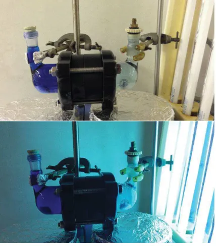
An example of TiO2 photocatalysis application in field of water purification is displayed in
Figure 1-7. [40] The consecutive system is devoted to treat relatively large volume of water kept at low energy consumption. The electrolysis- and photocatalysis-treatment system is composed of boron-doped diamond (BDD) electrode and TiO2 photocatalyst in the individual
unit. High-level wastewater passed through a pre-filter and circulated in an electrolysis unit containing the BDD electrode. Then the water source was converted into low-level wastewater, which was continually circulated in a photocatalysis unit. The photoreactor was packed with TiO2 coated quartz tubes under the sunlight. In the last step, the wastewater was
flowing into a final-filter and ion exchange filter unit. All the electricity power was supplied from solar energy through the photovoltaic cells in this work, which is another attractive characteristic of this system.
27
Fig. 1-7 Solar-driven electrochemical and photocatalytic water treatment system (a) photograph and (b) graphic illustration. [40]
1.2.2 Crystal phase, band gap and surface reactions of TiO2
In the nature crystalline TiO2 materials exists in three phases as: rutile, anatase and brookite.
Rutile is the most thermal stable form of TiO2 crystal, while anatase and brookite phases
could transform into rutile at high temperature. Anatase has been pointed out having the highest photocatalytic efficiency according to the most studies. [36, 83, 84] Yet some have claimed that a mixture of anatase and rutile with certain composition ratio could work better. [47, 85] Nevertheless, brookite is the phase that has been the less rarely studied for photocatalytic activity. [86, 87]
28
Band gap (Eg) of anatase, rutile and brookite differs depending on the crystal structures and
electronic band edges. It is one of the reasons that the specific TiO2 crystal phase has different
photocatalytic efficiency. Anatase is a common phase obtained from sol-gel and chemical deposition synthesis. Rutile structure would be usually developed when TiO2 is annealed
more than 700 °C. Pure brookite without the other two phases is difficult to prepare and it could be sometimes observed as a by-product in acidic-medium and low-temperature preparation. [86] Schematic unit cells of anatase, rutile and brookite are presented in Figure 1-8 and their symmetry and physical properties are listed in Table 1-1.
The prevalent crystal face (110) in anatase phase and the prevalent face (110) in rutile are highlighted in a grey color in Figure 1-9(a) and Figure 1-9(b) respectively, where the lattice constants in unit angstrom (Å) and x, y and z-axes corresponding to (100), (010) and (001) directions. The major crystal faces contained in anatase, rutile and brookite are listed in Table 1-2.
Fig. 1-8 Schematic unit cell of TiO2 (a) anatase, (b) rutile and (c) brookite presenting Ti atom
29
Table 1-1 Unit cell indices and physical properties of TiO2 anatase, rutile and brookite. [36,
83]
Fig. 1-9 Schematic crystal faces of TiO2 with Ti (white color) and O (red color) atoms and
lattice length in Å: (a) the anatase (101) surface and (b) the rutile (110) surface. [89]
Crystal phase Anatase Rutile Brookite
Molecular formula TiO2 TiO2 TiO2
Formula weight (g mol-1) 79.89 79.89 79.89
Z
(formula units per unit cell) 4 2 8
Crystal system Point group Space group Tetragonal 4/mmm I41/amd Tetragonal 4/mmm P42/mnm Orthorhombic mmm Pbca Unit cell a (Å) b (Å) c (Å) Volume (Å3) 3.784 3.784 9.514 136.25 4.585 4.585 2.953 62.07 9.184 5.447 5.145 257.38
Molar volume (cm3 mol-1) 20.156 18.693 19.377
Density (g cm-3) 3.895 4.274 4.123
30
Table 1-2 Main crystal faces of TiO2 anatase, rutile and brookite. [36, 89, 90]
Anatase has three main faces (101), (001) and (100), among which the first two faces are low in energy and thermally stable. [91, 92] Surface (101) is the most commonly observed one in anatase material. Surface (001) can undergo a 4-folded reconstruction so that (004) can be usually observed in XRD analysis on anatase phase. [91, 93] Similarly surface (100) can undergo a 2-folded reconstruction into (200), which is more often detected in rod-like anatase. [93] In the bulk structure, anatase has Ti atom as 6-coordinating, while O atom bonding with three Ti atoms. On the surface (101) there are rows of bridging oxygen (just connecting two Ti atoms) and rows of 5-coordinated Ti atoms. [94] The exposed Ti atoms are low in electron density acting as Lewis acid sites. Schematic graphs and SEM images of anatase single crystal are exhibited in Figure 1-10 with surfaces (001) and (101) being pointed out. [95]
Fig. 1-10 Anatase TiO2 crystals with a predominance of low index facets: Schematic (A) and
SEM images (B-D) of anatase TiO2 single crystals with different percentages of (001), (101),
and (010) facets. [95]
Crystal phase Anatase Rutile Brookite
Main crystal faces
(101) (001) (100) (110) (100) (001) (100) (110) (010)
31
Rutile has three major crystal faces as (110), (100) and (001) with the first two surfaces low in energy. [96] Surface (110) is most thermally stable and has rows of bridging oxygen with alternating 5-coordinate Ti atoms running parallel on oxygen row as schematically presented in Figure 1-11. [38] The red rectangle framed (O-Ti4+-O) is active site for water adsorption, electron transfer and proton transfer. The blue rectangle included bridging oxygen is responsible for electron and proton transfer. The green rectangle of (Ti4+-O-Ti4+) is available for oxygen-oxygen coupling and desorption. Surface (100) has similar rows of bridging oxygen and alternating Ti atoms in a different geometric relationship.
Brookite includes major crystal faces (100), (110) and (010) whose thermal stability reduces along in the order. [97] As mentioned previously, brookite is more difficult to synthesize in its pure form and is less studied as a catalyst.
Fig. 1-11 Schematic top view of the rutile (110) surface with bridging oxygen and 5-coordinated Ti atoms: colored rectangle (blue, red and green) responsible for various
possible interactions. [38]
General photocatalytic reactions over TiO2 particle include: 1) electron scavenger (e.g. Ti3+)
interacting with surface adsorbed oxygen and forming superoxide radical ion (•O2–) and 2)
hole scavenger (e.g. lattice oxygen) interacting with adsorbed water and forming hydroxyl radical (•OH). Hydroxyl radical •OH, superoxide ion •O2– and trapped hole $% could all
possibly degrade aqueous organic compounds (R) through intermediate reactions to the mineralized products as CO2 and H2O. [33]
TiO2 surface reaction:
32
Ti (III) + O2 → Ti (IV) + •O2– (1-20)
H2O + $% → •OH + H+ (1-21)
Degradation of organic molecules (R):
R + •OH → …→ Intermediates → …→ CO2 + H2O (1-22)
R + •O2– → …→ Intermediates → …→ CO2 + H2O (1-23)
R + $% + •O2– → …→ Intermediates → …→ CO2 + H2O (1-24)
Band gap energy (Eg) of TiO2 is the energy difference between its valance band maximal level
(VBM) and conduction band minimal level (CBM). The concept of direct and indirect Eg has
been explained in details in the previous session 1.1. TiO2 anatase of indirect band gap and
rutile of direct band gap are presented in Figure 1-12(a) and 1-12(b), respectively. [36]
Fig. 1-12 Indirect band gap of (a) anatase and direct band gap of (b) rutile. [36] The outer electron orbitals of Ti and O atoms are given as below:
Ti: 3s2 3p6 3d2 4s2
33
The “bonding” valence band in TiO2 consists of hybridization of Ti 3d and O 2p states. The
“anti-bonding” conduction band contains electrons mainly from Ti 3d state (with a few O 2p state and Ti 3p state). [36] Energy is dissipating through thermal vibration via “phonon” particles and/or irradiation via particle “photon” particles during charges relaxation and recombination processes. Indirect transition requires more change of momentum and thus charge recombination rate is slower in anatase (indirect transition) than that of rutile (direct transition). It is considered as one reason that anatase could usually perform better photocatalytic efficiency than rutile does.
Band gap energy (Eg) of TiO2 depends on crystal phase, composite purity and structural
properties and the relevant values have been experimentally and theoretically studied in many works. Optical techniques are common used to determine Eg experimentally [34, 98, 99],
whereas molecular orbitals calculation and density function theory (DFT) are often applied to calculate Eg theoretically [88, 100]. Generally, anatase is commonly reported having Eg as
3.23 eV, rutile 3.02 eV and brookite 3.14 eV. [10] In more recent studies, observed Eg value
of anatase has been reported varying from 3.0 to 3.6 eV (310 – 390 nm) according to synthetic TiO2 materials from different works. [36, 98, 101, 102]
Utilizing solar energy could greatly reduce the cost of photocatalyzed AOP treatment in wastewater, however, only 5% of UV energy (required in pure TiO2 photocatalysis process) is
composed in the sunlight. On the other hand, sunlight is especially abundant in some area where clean water severely lacks (e.g. in the deserts). An example of solar-driven electrochemical and photocatalytic water treatment system has been presented in Figure 1-7 of session 1.2.1.
Fig. 1-13 Various schematic graphs of possible band gap of pure or modified TiO2 materials
34
oxygen-deficient TiO2, (d) midgap energy levels for non-metal doped TiO2 and (e) both
oxygen vacancy and non-metal doped midgap levels are considered. [38]
Narrowing the band gap by doping heteroatoms in TiO2 materials could lead to absorbance
shift from UV to visible light. A graphic mechanism on Eg reduction due to dopant atoms
and/or oxygen deficient is given in Figure 1-13. [38] Either electron acceptor or oxygen deficient could degrade the minimal energy levels of conduction band as shown in Figure 1-13(c). Meanwhile, electron-donor atoms could upgrade the maximum energy levels of valence band as shown in Figure 1-13(d). The least band gap would be obtained in a case of both oxygen vacancy and non-metal dopants are present in the photocatalyst as seen in Figure 1-13(e). As a result, midgap levels reduce the band gap so that solar energy of its visible band is sufficient to initiate photocatalyzed oxidation reactions.
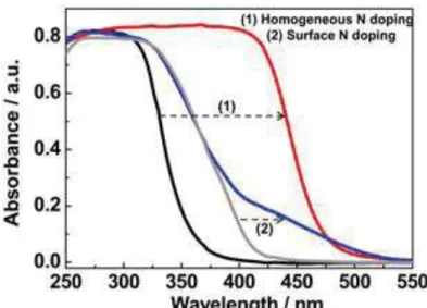
Fig. 1-14 Homogeneous N doping in Cs0.68Ti1.83O4. The left panel: UV-visible absorption
spectra of (1) homogeneous N doped Cs0.68Ti1.83O4 and (2) surface N doped TiO2. [103]
Doping TiO2 materials with heteroatoms such as non-metal atoms (e.g. N and F) [6, 103-107]
and metal atoms (e.g. W and Ag) [108, 109] has been carried out in several works aimed at solar harvesting. Dopant TiO2 could sustain a smaller band gap (i.e. larger absorbance
wavelength) when electron acceptor (non-metal atoms as dopant) and electron acceptor (metal atoms) are incorporated. A comparison between pure TiO2 and nitrogen-dopant TiO2 (either
35
[103] Apparent absorbance shift to the visible spectrum has been witnessed on the N-dopant TiO2 sample.
1.3 TiO2 photocatalytic membrane reactors (PMRs)
Photocatalyzed oxidation initiated by photo-generated •OH radical and/or trapped holes is clarified as an innovative technology of advanced oxidation processes (AOPs). Since concept of AOPs was first stated in 1987 by Glaze and et al. [2], there are about 500 industrial-scale AOP plants all over the world today. Photocatalyzed AOP operation using TiO2/UV/O2
reduces the process cost by replacing the expensive oxidant reagents H2O2 and O3 with
ambient oxygen. Integration of photocatalytic oxidation with membrane process is essential for industry-scale application of PMRs in wastewater treatment filed.
1.3.1 Advanced oxidation processes (AOPs) for degrading pollutants
Advanced oxidation processes (AOPs) indicate a specific treating technique by decomposing contaminants in water through •OH oxidation reaction. [2] Some other strong oxygen species such as •O2–, O3 and H2O2 are also possibly involved in the process. It has been proven that
membrane process coupled with AOP operation can be particularly effective in eliminating non-degradable pollutants such as aromatics, pesticides, herbicides, volatile organic compounds (VOCs) and petroleum constituents in wastewater. [12, 110, 111] Proposed routes on phenol oxidation on illuminated TiO2 (as in •OH radical attack mechanism) are presented
in Figure 1-16 as an example. [112]
A major advantage of AOP treatment is to remove contaminants without bringing any secondary hazardous substances. And the treatment efficiency relies heavily on in-situ production of •OH radicals. Hydroxyl radical •OH, one of the strongest oxidant species next to fluorine, has oxidizing potential E0 (•OHaq/H2O) = 2.59 V at pH=0 [3] making it possible to
oxidize almost all types of organic compound. However, pre-treating the water source is sometimes needed to ensure reliability of AOP performance considering the chemistry of •OH radical. For instance bicarbonate ion (HCO3–), which can act as •OH scavenger, should be
wiped away before the AOP procedure. [113]
In conventional homogeneous AOP treatment, •OH radical could be formed by adding ozone (O3) and/or hydrogen peroxide (H2O2). Common homogenous AOP systems include
36
H2O2/Fe2+. More recently, solid semiconductor (Sc) for instance TiO2 photocatalyst is added
in the liquid phase and thus a heterogeneous AOP system is consisting as Sc/O2/UV.
Homogeneous/heterogeneous APO operations with or without irradiation are compared in Table 1-3. High cost of O3 and H2O2 used in conventional homogeneous AOP treatment is
limiting its industrial application to large-scale water plant.
Table 1-3 AOP operated systems to produce hydroxyl radical (•OH). [2, 113]
With irradiation Without irradiation
Homogeneous systems
O3/UV O3/H2O2
H2O2/UV O3/OH–
H2O2/Fe2+/UV H2O2/Fe2+
Heterogeneous systems
*Sc/O3/UV -
*Sc/H2O2/UV -
*Sc/O2/UV -
*Sc: semiconductor
Meanwhile, using semiconductor catalyst (TiO2) could lead to •OH radical formation by
replacing the costly oxidant reagents with only ambient oxygen. Furthermore, the membrane based AOP is in particular interested in water treatment method since immobilized phase of TiO2 (instead of suspetion) could be used in treated water. Therefore, no loss or separation of
the photocatalyst particles is necessary in the photocatalytical membrane process.
A schematic illustration on photocatalytic AOP pathway degrading organic pollutions into CO2 and H2O is presented in Figure 1-15. Photon energy is transferred to chemical energy
resulting in the formation of •OH radical as the catalyst is in contact with H2O and O2. In the
presence of semiconductor (Sc) catalyst, O3 or H2O2 is no more mandatory for •OH generation,
yet the presence of them could still enhance the catalytic activity reported in some studies. [110, 111, 114]
37
Fig. 1-15 Concept of photocatalytic AOP system (containing Sc/UV/O2) that mineralizes
organic compounds into the end products H2O and CO2.
TiO2 is the most-often applied photocatalyst in current research works. Photocatalytic AOP
system of TiO2/UV/O2 works as effective and economical technique degrading aqueous
organic pollutants for environmental remediation. Proposed photodegradation mechanism of phenol over illuminated TiO2 (through radical attack) is given as an example in figure 1-16.
Continuous oxidation including aromatic ring opening and carbon bond breaking (through many intermediate reactions) could lead to mineralization of the organic compound ending in the final products as water and carbon dioxide.
Fig. 1-16 A possible mechanism of phenol destruction on illuminated TiO2. [112]
Dispersed TiO2 as suspension in solution has been first frequently experimented in many
works. [76, 94, 115] Degussa P25 TiO2 powder (from Evonik) as a “gold standard”
38
mixture of anatase and rutile in a ratio 80% : 20% in weight. The particles have surface area ca. 50 m2/g and size less than 25 nm. Both the nature of photocatalyst and conditions in the solution and irradiation source are found as important parameters for photodegradation efficiency. However, it is quite often reported that removing TiO2 powders from the treated
liquid flow is very difficult. [38, 40] Filtration is obliged after treatment with catalyst powder and loss of the catalyst is found to be 30% when recycling reported in one study [59]. It is indeed the technical “bottleneck” of the suspended system when scaling up it to industrial application.
Subsequently, a lot of efforts are made on integrating membrane separation and immobilizing TiO2 particles (e.g. the P25 powders) on mechanical support. In the beginning, TiO2 layers
have been immobilized on glass and silicon supports with methods including sol dip-coating, physical vapor deposition and chemical vapor deposition. [90, 116, 117] More recently, TiO2
has been coated on membrane substrate and consequently surface reaction and separation process could be integrated in one photoreactor. [15, 114, 118] Producing porous TiO2
coating layer with large specific surface area is aimed at improving catalytic efficiency in the immobilized phase.
1.3.2 Membrane separation integrated with photocatalytic AOP treatment
Membrane is a thin and selective barrier through which both matter and energy could pass under some certain force. Since the 19th century artificial membranes have been attempted and manufactured for different functions as contactor, distributor and reactor. Artificial membranes are found in polymers, inorganic composites, ceramics and metals nowadays. General membrane modules include flat-sheet, spiral wound, tubular and hollow fibers. Membrane processes are spatially economical, consuming less energy and depleting fewer less chemicals in continuous and stable performance. They can be found in daily life as producing clean water, recovering valuable resources, concentrating solutes (e.g. in beverages and pharmaceutics) and separating gases/vapors.
Driving force indicates the thermodynamic potential on membrane and it contains the difference in concentration, pressure, temperature and electric potential. Definition of driving force (F) is given as the ratio between differential potentials against membrane thickness as written in Equation 1-25.
![Fig. 1-1 Band gap in different materials: metal, semiconductor and insulator. [32]](https://thumb-eu.123doks.com/thumbv2/123doknet/14526819.723080/15.892.200.659.358.610/fig-band-gap-different-materials-metal-semiconductor-insulator.webp)
![Fig. 1-2 Energies for various semiconductors in aqueous electrolytes at pH=1. [33]](https://thumb-eu.123doks.com/thumbv2/123doknet/14526819.723080/16.892.230.609.362.698/fig-energies-various-semiconductors-in-aqueous-electrolytes-ph.webp)
![Fig. 1-26 SEM images of TiO 2 /Al 2 O 3 composite membrane : dip-coated TiO 2 layers on (a) 5 nm pore-sized top layer Al 2 O 3 [123] and (b) tubular macroporous Al 2 O 3](https://thumb-eu.123doks.com/thumbv2/123doknet/14526819.723080/50.892.110.728.123.378/images-composite-membrane-coated-layers-sized-tubular-macroporous.webp)