RUGC 2021 AJCE, vol. 39 (1)
63
Experimental study on the influence of the
preload in RC structures strengthened with
CFRP.
Andrea Armonico, Mohamed Saidi, Laurent Michel, Sylvain Bel, Emmanuel Ferrier University of Lyon, University Lyon1, Laboratory of Composite Materials for Construction (LMC2),
82 bd Niels Bohr 69622 Villeurbanne, France.
ABSTRACT Concrete buildings represent a large part of the world’s structures. Long-term effects represent a critical issue for this kind of construction making it necessary to develop reinforcement systems (i.e. composite materials). A large part of nowadays research is focused on composite materials study in terms of durability, resistance increase, and good practices. The present work investigates the influence of CFRP sheets reinforce in terms of global behavior and crack opening. Using digital image correlation technology, crack development is studied after beam retrofitting in a no-damaged stage and in a cracked stage respectively. The study points out the influence of the pre-load in reinforced beams in terms of crack width, taking into account steel strain level equal to 80% of the elastic limit strain.
Keywords: CFRP, RC Beams, DIC, CRACK OPENING
I. INTRODUCTION
Concrete buildings represent a large part of the world’s structures. Long-term effects are a critical issue for this kind of construction making it necessary to develop reinforcement systems (i.e. composite materials). Research has devoted the last few years to providing formulation and theories, together with good practices for RC strengthening. Composite solutions, in this sense, represent the new era of civil engineering because of the high resistance and durability of these materials. Normally, a strengthening design considers no damaged sections. Cracks opening study could be useful to estimate the structural damage. This paper investigates the influence of an existing crack pattern in terms of global behavior and cracks opening to enhance the influence of CFRP on cracking behavior. Digital image correlation technology was used for the crack opening assessment for several load steps. Likewise, traditional tools are used for global behavior evaluation (i.e. strain gauges, LVDT).
Two types of reinforcement are analyzed: the first one in which two layers of CFRP were applied on a no-damaged beam, the second one in which the beam was pre-loaded until 80% of the elastic limit steel deformation before the reinforcement.
RUGC 2021 AJCE, vol. 39 (1)
64 The first part of the paper is focused on the materials' mechanical properties, the second part describes the experimental campaign and the test set-up. At the end of the paper are presented some results with a short discussion.
II. MATERIALS
The work was focused on the crack developing behavior of 2300 mm reinforced concrete beams, through carbon fiber reinforced polymers (CFRP) sheets.
A. Reinforced concrete
Reinforced concrete beams were made with a compressive strength concrete (fck) of 45 MPa at
bending test time. The concrete mix design is reported in table 1. Beams reinforce consist of 2 different diameters of steel rebar, having a characteristic yield strength (fyk) of 500 MPa. To
distinguish the specimens will be named according to the diameter of the bending reinforcement, R10 and R14 respectively for 12 mm rebar and 14 mm rebar.
TABLE 1Concrete mix design
Component Cement CEM I 52,5 R Sand Gravel Water
[kg/m3] 420 890 890 200
B. CFRP reinforcement
Beams were retrofitted employing Betontex FB-GV330U-HT carbon fiber reinforced polymer by Fibre Net s.p.a. having a section of 1900 x 100 mm2. The fiber was glued using a bicomponent
epoxy resin Betontex FB-RC02 produced by Fibre Net s.p.a. . The geometrical and mechanical properties of the material are reported in table 2.
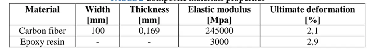
TABLE 2 Composite materials properties
Material Width [mm] Thickness [mm] Elastic modulus [Mpa] Ultimate deformation [%] Carbon fiber 100 0,169 245000 2,1 Epoxy resin - - 3000 2,9
III. EXPERIMENTAL PROGRAM
The work is focused on the influence of CFRP sheets reinforce, in crack opening and spacing on small-scale RC beams.
A. Specimens preparation
The specimens set consists of four reinforced beams. Two of them were reinforced employing 2 CFRP layers without any damage named “Reinforced Before” (RB). The other two beams were reinforced in the same way as the previous ones but after a pre-loading until 80% of the steel elastic limit deformation (y) equal to 1.9 ‰ named “Reinforced Unloaded after 80%” (RU80). All the specimens are equipped with two strain gauges on steel reinforcing.
In table 3 geometrical properties and specimens set up are reported. The specimens were
reinforced using two CFRP layers having a 100 x 1900 mm2 section. The bottom surface was
RUGC 2021 AJCE, vol. 39 (1)
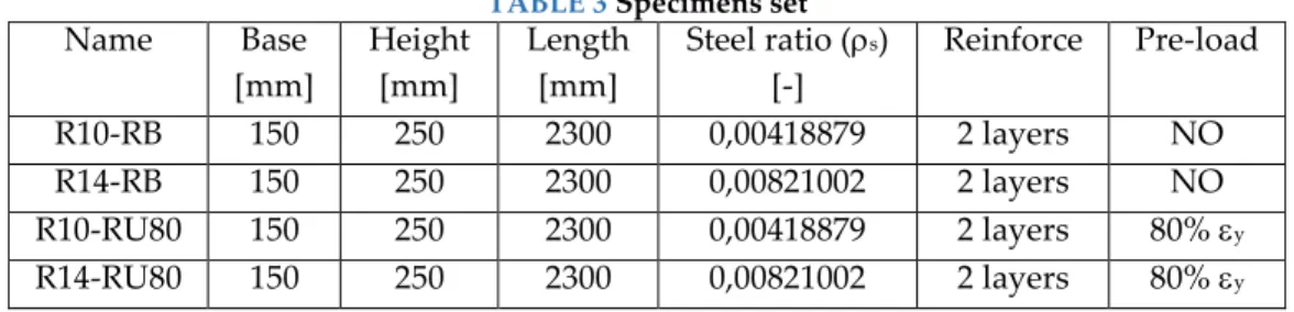
65 TABLE 3 Specimens set
Name Base [mm] Height [mm] Length [mm] Steel ratio (s) [-] Reinforce Pre-load R10-RB 150 250 2300 0,00418879 2 layers NO R14-RB 150 250 2300 0,00821002 2 layers NO R10-RU80 150 250 2300 0,00418879 2 layers 80% y R14-RU80 150 250 2300 0,00821002 2 layers 80% y B. Test set-up
The bending tests were conducted through a 4 point bending failure. The beam span was equal to 2000 mm and the load point wheelbase was set to 600 mm. The load was applied by a hydraulic jack, placed in the center of the beam. The test was performed with a speed of 1mm/min in isostatic condition. The beams were equipped with strain gauges on the steel surface and the carbon reinforcement at the center of the beam. The strain gauges had a resistance of 120 and a grid length of 10 mm. The LVDT displacement sensor was placed in the center of the beam. In figure 2 is reported the configuration for the bending test set-up.
FIGURE 1 Bending test set-up
C. Digital image correlation (DIC 2D)
Digital imagine correlation (DIC) is a non-contacting optical technique based on correlation theories for data alteration measures. A set of grey-scale photos was taken using a KOWA LM25HC lens. Beam inspected surface has been prepared with white paint and black speckles as reference for image correlation. The post-processing was performed by GOM Correlate software. A region of interest (ROI) was defined. It contains small facets called area of interest (AOI) with well-defined pixel sizes. The AOIs size is directly proportional to speckles dimension. The AOIs centers and the distance between them were defined by the software taking it as a reference. The next images’ distances are compared with the referential, generating displacement and strain field mapping.
IV. RESULT AND DISCUSSION
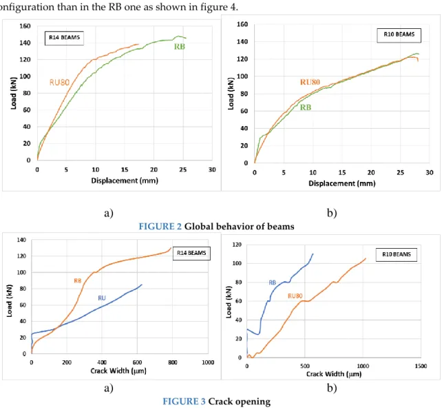
DIC acquiring provides crack width development during the bending test. On the other side, the LVDT displacement sensors allow to define global behavior of the specimen. In particular, two different times of reinforcement were evaluated. As reported in figure 3 global behavior wasn’t
RUGC 2021 AJCE, vol. 39 (1)
66 affected by this parameter. Crack opening, conversely, presents a faster development in the RU configuration than in the RB one as shown in figure 4.
a)
b)
FIGURE 2Global behavior of beams
a)
b)
FIGURE 3Crack opening
The experimental test highlights the influence of steel strain in retrofitting crack opening effects. At the same time, no global effect was noted making the flexural capacity due to steel contribute.
REFERENCES
H. Varastehpour, P. Hamelin, Analysis and study of failure mechanism of RC beam strengthened with FRP plates, Second international conference on composite material for bridge and structure, Montreal (Canada), 11-15 August 1996
Pham, H., & Al-Mahaidi, R. (2004, May). Flexural retrofitting of concrete bridge beams using CFRP fabrics. In Austroads Bridge Conference, Hobart, Australia.
Verbruggen, S., Aggelis, D. G., Tysmans, T., & Wastiels, J. (2014). Bending of beams externally reinforced with TRC and CFRP monitored by DIC and AE. Composite structures, 112, 113-121.