Publisher’s version / Version de l'éditeur:
Vous avez des questions? Nous pouvons vous aider. Pour communiquer directement avec un auteur, consultez la
première page de la revue dans laquelle son article a été publié afin de trouver ses coordonnées. Si vous n’arrivez pas à les repérer, communiquez avec nous à PublicationsArchive-ArchivesPublications@nrc-cnrc.gc.ca.
Questions? Contact the NRC Publications Archive team at
PublicationsArchive-ArchivesPublications@nrc-cnrc.gc.ca. If you wish to email the authors directly, please see the first page of the publication for their contact information.
https://publications-cnrc.canada.ca/fra/droits
L’accès à ce site Web et l’utilisation de son contenu sont assujettis aux conditions présentées dans le site LISEZ CES CONDITIONS ATTENTIVEMENT AVANT D’UTILISER CE SITE WEB.
Research Report (National Research Council of Canada. Institute for Research in Construction), 2008-09-12
READ THESE TERMS AND CONDITIONS CAREFULLY BEFORE USING THIS WEBSITE.
https://nrc-publications.canada.ca/eng/copyright
NRC Publications Archive Record / Notice des Archives des publications du CNRC :
https://nrc-publications.canada.ca/eng/view/object/?id=34b174d0-798d-47ef-a9ea-d53fc3b4cc48 https://publications-cnrc.canada.ca/fra/voir/objet/?id=34b174d0-798d-47ef-a9ea-d53fc3b4cc48
NRC Publications Archive
Archives des publications du CNRC
For the publisher’s version, please access the DOI link below./ Pour consulter la version de l’éditeur, utilisez le lien DOI ci-dessous.
https://doi.org/10.4224/20373946
Access and use of this website and the material on it are subject to the Terms and Conditions set forth at International Road Tunnel Fire Detection Research Report - Phase II Task 1: Fire Detectors, Fire Scenarios and Test Protocols
Liu, Z. G.; Crampton, G. P.; Kashef, A.; Lougheed, G. D.; Gibbs, E.; Su, J. Z.; Bénichou, N.
International Road Tunnel Fire Detection Research Project – Phase II
Task 1: Fire Detectors, Fire Scenarios and Test Protocols
Prepared by
Z. G. Liu, G. Crampton, A. Kashef, G. Lougheed, E. Gibbs, J. Z. Su and N. Benichou
Fire Research Program
Institute for Research in Construction
International Road Tunnel Fire Detection Research Project – Phase II
Project Technical Panel
Frank Gallo, Port Authority of New York and New Jersey Harry Capers, New Jersey DOT
Jesus Rohena, Federal Highway Administration Paul Patty, Underwriters Laboratories Inc. Volker Wetzig, Versuchs Stollen Hagerbach AG Art Bendelius, A & G Consultants
Bill Connell, Parsons Brinckerhoff
Margaret Simonson, Swedish National Testing and Research Institute Gary English, Seattle Fire Department
Peter Johnson, ARUP Fire Risk & Security Jim Lake, NFPA staff liaison
Principal Sponsors
Ministry of Transportation, British Columbia Ministry of Transportation of Ontario
Quebec Ministry of Transportation axonX LLC
Siemens Building Technologies Tyco Fire Products
VisionUSA
Sureland Industries
United Technologies Research Corporation
Contributing Sponsors
National Research Council of Canada
Port Authority of New York and New Jersey A & G Consultants
PB Foundation Micropack, Inc. Spectrex, Inc. Honeywell Inc.
ABSTRACT
This report presents the activities completed in Task 1 of the International Road Tunnel Fire Detection Research Project – Phase II. These activities include the selection of ten fire detection systems representing five types of currently available technologies for the fire test program. Each system meets the requirements established by the projects Technical Panel for the application of fire detection systems in tunnels, and meets the recommendations from Phase I of the project – Review of Prior Test Programs and Tunnel Fires. The five technology types are: linear heat detection systems, flame detectors, CCTV fire detectors, smoke detection systems and spot heat detectors. General information and operating principles of these systems are described in the report.
The fire detecting, locating and monitoring capabilities were identified as important parameters related to the performance of fire detection systems for tunnel protection. Three types of fire scenarios, which are representative of the majority of tunnel fire incidents, were selected for use in evaluating the performance of the tunnel fire detection systems. They are a pool fire scenario with fast growth rates, a stationary vehicle fire scenario with slow growth rates, and a moving fire scenario.
The requirements for design and installation of the detection systems in the test program were also set up. Mock-ups and fire sources in the test program were constructed and their heat release rates measured. General information on the instrumentation to be use in monitoring fire tests is also described in the report. In addition, a test plan for the tunnel fire test program (Task 2) is proposed in the appendix.
ACKNOWLEDGEMENTS
The project is carried out under the auspices of the Fire Protection Research Foundation (FPRF). The authors would like to acknowledge the support of the Technical Panel and Sponsors to this project. It is also acknowledged that some information used in the report is provided by members of the Technical Panel. A special acknowledgement is noted to Kathleen Almand of the FPRF for her contribution in organizing the project.
TABLE OF CONTENTS
1. Introduction ...6
2. Selected Fire Detection Systems...6
3. General Requirements for Fire Detection Systems in Fire Tests ...11
4. Performances of Fire Detection Systems to be Evaluated ...11
5. Fire Scenarios...12
5.1 Pool Fires ...12
5.1.1 Pool Fires underneath Vehicle ...13
5.1.2 Pool Fires behind Large Vehicle...13
5.2 Stationary Vehicle Fires...14
5.3 Moving Fires...15
6. Mock-ups and Fire Sources ...15
7. Instrumentations...24
8. Summary.………..24
References………..26
1. INTRODUCTION
The research conducted in Phase I of the International Road Tunnel Fire Detection Research Project [1] indicated that information on the performance of current fire detection systems and guidelines for their use in road tunnel protection are limited. Relatively few test programs that document the performance of current tunnel fire detection systems during fires have been reported. These programs mainly involved either linear heat detection systems or flame detectors [2-8]. Detector performance was usually evaluated with pool fires of a constant heat release rate (up to 3 MW), while other types of fire scenarios, such as stationary vehicle fires with a slow growth rate or moving vehicle fires encountered in tunnel fire incidents, were not considered. Moreover, there is increasing interest in the use of Closed Circuit Television (CCTV) as a component of a fire detection system [9-11], but information on CCTV and other types of fire detection technologies, such as spot heat and smoke detection systems, for tunnel protection is limited.
Based on the requirements for the application of fire detection systems for tunnel protection as well as the recommendations from Phase I of the project, six tasks will be carried out in the present project to investigate the detection capabilities and reliability of current fire detection systems. The work covered in this report, Task 1, includes the selection of representative detection systems representing currently available technologies, establishing appropriate performance evaluators, and the development of appropriate fire scenarios to investigate the fire detecting capabilities of these systems. The work undertaken in Task 1 includes the establishment of mock-ups and fire sources to be used in both laboratory (Task 2) and field tunnel (Task 4) fire tests.
This report presents the work carried out in Task 1. In addition, the test plan for Task 2 of the project – laboratory tunnel fire tests – was developed and is presented in Appendix 1. The test plan for Task 4 of the project – field tunnel fire tests – will be developed after appropriate fire sources and test procedures are identified using the results of Task 2.
2. SELECTED FIRE DETECTION SYSTEMS
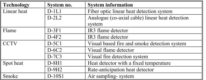
Ten different fire detection systems have been selected for the fire test programs by the Technical Panel. These systems cover five types of currently available technologies. They are: linear heat detection systems, flame detectors, CCTV fire detectors, smoke detection systems and spot detectors. These systems provide a good representation of current fire detection technologies for use in tunnel fire detection. Information on these systems is listed in Table 1.
Table 1. Fire Detection Systems in Test Program Technology System no. System information
D-1L1 Fiber optic linear heat detection system Linear heat
D-2L2 Analogue (co-axial cable) linear heat detection system
D-3F1 IR3 flame detector Flame
D-4F2 IR3 flame detector
D-5C1 Visual based fire and smoke detection system D-6C2 Visual flame detector
CCTV
D-7C3 Visual fire detection system
D-8H1 Heat detector with a fixed temperature Spot heat
D-9H2 Rate-anticipation heat detector Smoke D-10S1 Air sampling- system
System D-1L1 is a fiber optic linear heat detection system based on Raman scattering. The optical fiber is used as the sensing medium. During operation, light signals are sent into the optical fiber from a laser light source (Figure 1). As pulses travel down the fiber, light is lost through scattering. A portion of the scattered signal is directed back along the fiber towards the laser source. Part of the back-scatter signal (Roman Scattering) is used to provide remote temperature measurements as changes in temperature alters the refractive indices and geometric properties of the optical fiber, which perturbs the intensity, phase, and polarization of the light wave propagating within the fiber. Fire warning signals are given based on rate of temperature rise and/or exceeding a fixed temperature. The system can also provide information on the fire location along the fiber cable.
System D-2L2 is an analogue (coaxial cable) linear heat detection system. The sensor cable consists of a conductor, an insulating layer with a resistivity that decreases with increasing temperature, and a metal-weaving screen layer (Figure 2). During a fire incident, the resistance between the conductor and the metal screen drops due to the increase in temperature. The changes in the resistance can then be monitored using a control module, and a fire warning signal provided based on rate of temperature rise or exceeding a fixed temperature.
Figure 2. Schematic of the sensor cable of System D-2L2
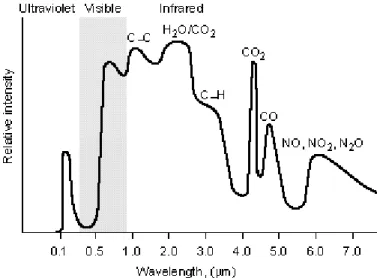
Both systems D-3F1 and D-4F2 are multi-spectrum infrared (IR) flame detectors supplied from two different manufacturers. System D-3F1 contains three IR sensors: one covers the typical CO2 flame emission spectral band (Figure 3) that is responsible for the
detection of flame radiation, and the other two sensors cover different, adjacent, and specially selected spectral bands, where black body emitters and background radiation are produced and are used to minimize false alarms. System D-4F2, like System D-3F1, also uses an IR sensor to cover the CO2 flame emission spectral band, but it uses an optical filter that enables
a single IR sensor to measure the radiated energy present in two separate spectral bands on either side of the flame emission spectral band.
Systems D-5C1 and D-6C2 are Closed Circuit Television (CCTV) fire detection systems supplied by two different manufacturers. They use a combination of video cameras, computers, and artificial intelligence techniques (Figure 4) for fire detection. A video charged-couple device (CCD) camera is used to monitor the environment and possible fire incident. The spectral output of the camera is stored in computer memory as a function of time and space. Pattern recognition and image processing techniques are used to analyze the images on the fly. Fire alarms will be issued, once the characteristics of flame and smoke are identified. Video images provided by the system are also used to track and monitor the fire growth.
Figure 4. Operating principles of a CCTV fire detection system
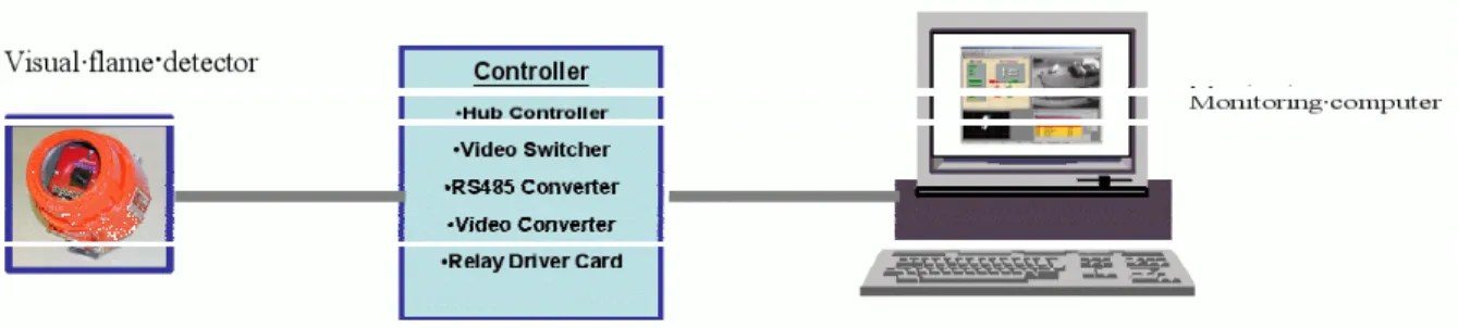
System 7C3 is another type of CCTV flame detection system. Unlike Systems D-5C1 and D-6C2, image sensing and processing are combined into one detector, and fire information and videos are directly sent to the monitoring computer through a controller, once a fire incident is identified (Figure 5).
Figure 5. Operating principle of System D-7C3
System D-8H1 is a pneumatic, spot type heat detection system based on frangible bulb technology (Figure 6). The device is fitted on a sensing line pressurized using nitrogen. During a fire incident, the air trapped in the line will be released as the detector is activated, triggering a pressure switch that provides a fire signal and indicates the fire position located at which the detection segment is.
Figure 6. Spot type heat detector of System D-8H1
System D-9H2 is a rate-anticipation spot heat detector (Figure 7). It responds and activates the fire alarm when the ambient temperature reaches the preset temperature setting. Under rapid heat rise conditions, its rate-anticipation feature also enables the detector to respond one to three degrees ahead of the temperature setting.
Figure 7. Spot type heat detector of System D-9H2
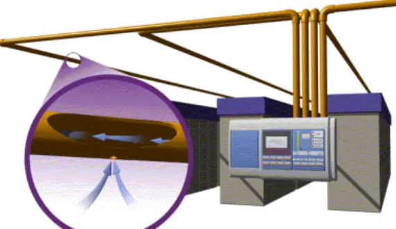
System D-10S1 is an air sampling-type smoke detection system. Air is continuously drawn into a pipe network through holes in the piping to a centrally-located smoke detector using an air pump or aspirator (Figure 8). The density of smoke in the sampled air is then compared to a set of pre-defined smoke thresholds. Alarms will be issued, if the amount of smoke in the sampled air exceeds the thresholds.
3. GENERAL REQUIREMENTS FOR FIRE DETECTION SYSTEMS IN FIRE TESTS
All the selected fire detection systems are to be installed in the test tunnel by the manufacturers and evaluated under the same fire test conditions. Their installation configurations will not be changed during the test program.
The configuration and installation of the fire detection systems in the test tunnel will be designed assuming a road tunnel with a dimension of 10 m wide x 5.5 m high x 2,000 m long (30 ft x 16.5 ft x 6,100 ft long). The sensitivity level of the fire detection systems used in the fire test program will be the same as those used in the operating environment tests in the Lincoln tunnel of the Port Authority undertaken in Tasks 5 and 6 of the project.
The total length of the sensing cable of linear heat detection systems used in the tests will be the maximum sensing length of the system. The cable installed on the ceiling of the tunnel facility will be at the maximum sensing length of the system recommended by the manufacturer. These requirements are used to evaluate the fire detecting and locating capabilities of the system.
Flame detectors will be installed on the wall of the tunnel. For fire tests of Task 2 in the laboratory tunnel, the distance from the detector to the fire source will be the lesser of 31 m (100 ft), or the maximum distance recommended by the manufacturer. For fire tests of Task 4 in the operating tunnel, the distance from the detector to the fire source will be the maximum distance recommended by the manufacturer. The installation of the detectors will be such that their field of view covers the entire tunnel.
CCTV fire detectors will be installed on the wall of the tunnel. For fire tests of Task 2 in the laboratory tunnel, the distance from the detector to the fire source will be the lesser of 31 m (100 ft), or the maximum distance recommended by the manufacturer. For fire tests of Task 4 in the operating tunnel, the distance from the detector to the fire source will be the maximum distance recommended by the manufacturer. The installation of the detectors will be such that their field of view covers the entire tunnel.
Spot heat detectors will be installed on the ceiling of the tunnel. The fire source will be located at a point equidistant from the two nearest detectors.
Air sampling pipes of the smoke detection system will be installed on the ceiling of the tunnel. The fire source will be located near the end of a zoned pipe network.
4. PERFORMANCE OF FIRE DETECTION SYSTEMS TO BE EVALUATED
Performance of fire detection systems will be evaluated using selected tunnel fire scenarios in the test program. The following parameters related to the fire detection capability of the systems will be investigated, based on requirements for tunnel protection [1, 12-16]:
• Detecting capability to tunnel fire incidents depending on fire size, fire type, growth rate and location (measuring parameter: time (seconds));
• Capability to locate the fire position in the tunnel (measuring parameter: distance (meter));
The monitoring capability of some systems to a fire incident (i.e. fire growth and developing direction in the tunnel) will also be evaluated in the test program.
5. FIRE SCENARIOS
Three different fire scenarios, which are considered representative of the majority of tunnel fire incidents [1, 12, 14, 17, 18], were selected for use in evaluating the performance of the tunnel fire detection systems:
• Liquid pool fires caused by fuel leaking from a vehicle or in a collision. The fire develops very quickly and reaches its maximum heat release rate in a short time; • Stationary passenger vehicle fires caused by collision incidents, by an electrical
failure or by a defective fuel delivery system and exhaust system failures. The fire develops slowly and it takes 8 ~ 12 minutes for a vehicle fire to reach its maximum heat release rate; and
• Moving vehicle fires caused by an electrical failure or by a defective fuel delivery system and exhaust system failures. The fire size is approximately 100~150 kW while stationary.
5.1. Pool Fires
Two pool fire scenarios will be used in the test program:
• Pool fire scenario I – a pool fire underneath the vehicle, representing a challenging tunnel pool fire as the fuel leaks and forms a pool underneath the vehicle.
• Pool fire scenario II – an open space pool fire behind a large vehicle, representing a more general tunnel pool fire as fuel leaks and forms a pool behind the vehicle.
Obstacles that simulate other vehicles will be placed around the fire source. Gasoline pool fires of various sizes and a propane burner with a controlled heat release rate will be used as fire sources in the tests.
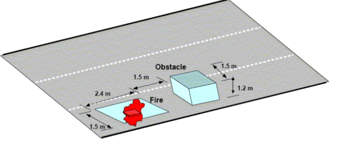
5.1.1. Pool Fires underneath the Vehicle
The schematic of a pool fire that occurs underneath a vehicle is shown in Figure 9. A steel plate will be located 0.3 m (1 ft) above the pan used for the pool fire. The plate will have an area of 1.5 m (5 ft) wide by 2.4m (8 ft) long, which is similar to the bottom area of a standard passenger vehicle. A vehicle mock-up with a size of 1.5 m (5 ft) wide by 1.2 m (4 ft) high, simulating a crashed car located between the fire source and the wall-mounted detectors, will be placed 1.5 m in front of the fire source and 0.3 m (1 ft) above the ground.
The size of the pan placed underneath the plate ranges from 0.3 m x 0.3 m to 1.0 m x 2.0 m. A propane burner that has a controlled heat release rate will also be used to simulate pool fires underneath a vehicle. The fire sizes in the test program will be varied approximately from 100 KW to 3,400 kW.
Figure 9. Schematic of a pool fire underneath a vehicle
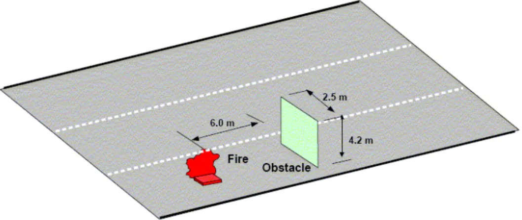
5.1.2. Open Pool Fires behind a Large Vehicle
The schematic of an open pool fire located behind a large vehicle is shown in Figure 10. It will be constructed by placing an open pan fire behind a large metal plate. The metal plate has a size of 2.5 m (8.3 ft) wide by 4.2 m (14 ft) high and is representative of the size of a large truck. It will be placed 6 m (20 ft) in front of the pool fire and 0.3 m (1 ft) above the ground, which simulates the front portion of a crashed truck located between the pool fire and the detectors. The distance between the edge of the metal plate and the wall of the tunnel will be 0.5 m (1.7 ft). The size of the pan placed behind the obstacle ranges from the size of 0.3 m x 0.3 m to the size of 1.0 m x 2.0 m. The fire sizes in the test program will be varied approximately from 100 KW to 3,400 kW.
Figure 10. Schematic of an open fire behind a large vehicle
5.2. Stationary Vehicle Fires
A stationary vehicle fire can start from the engine compartment, from the passenger area, or from the fuel tank and trunk area [19, 20]. The fire growth rate is slower than a hydrocarbon pool fire and it can take a long time for the flame to spread to the rest of the vehicle [21, 22]. Two stationary vehicle fire scenarios will be used in the test program: an engine compartment fire and a passenger compartment fire. No obstacles will be located between the fire source and the detectors. The schematic of the stationary vehicle fire scenario is shown in Figure 11.
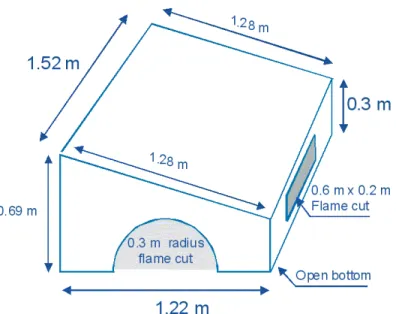
For an engine compartment fire scenario, a simulated vehicle engine compartment with a dimension of 1.5 m (5 ft) wide x 1.2 m (4 ft) long x 0.67 m (2.2 ft) high will be built. A gasoline fuel pan with controlled heat release rate will be placed inside the compartment and used to generate an engine compartment fire. The heat release rate will be similar to one generated in a real vehicle engine compartment fire [21, 22]. It will take approximately 8 minutes for the vehicle engine compartment fire to reach its maximum heat release rate (2,000 kW).
The propane burner that has a controlled heat release rate will also be used in the laboratory fire tests for simulating a vehicle engine compartment fire. This fire source will also be used in the field tests. It will take 8 minutes for the fire to reach its maximum heat release rate (2,000 kW).
For a passenger compartment fire scenario, a mock-up simulating the front portion of a vehicle passenger compartment with a dimension of 1.5 m (5 ft) wide x 1.2 m (4 ft) long x 1.2 m (4 ft) high will be built. It will be assumed that during the fire incident, the door at the driver side of the vehicle is left open, as the driver escapes from the burning vehicle. Wood cribs will be placed inside the compartment and used to generate a passenger compartment fire. An alcohol pan fire placed underneath the wood crib will be used as the ignition source. The heat release rate of the fire will be similar to one generated in a real vehicle passenger compartment fire [21, 22]. It will take approximately 10 minutes for the fire to reach its maximum heat release rate (1.1 ~ 1.5MW).
5.3. Moving Vehicle Fires
A moving vehicle fire can be caused by many factors including a fuel delivery failure that is ignited by hot exhaust components [19, 20]. The most common scenario is a parking brake that is left engaged causing the brake drum to overheat resulting in the rupture of the hydraulic slave cylinder seals. When this happens, the brake fluid is released into the drum and subsequently ignites. The wheel involved is in the rear of the vehicle and can go unnoticed by the driver. The fire eventually destroys the tire and spreads to the rear bumper and fuel tank once the vehicle stops. The moving vehicle fire is not only a realistic scenario that has occurred on many occasions in tunnels, but it is also a challenge for a detection system [1]. Since it can quickly develop into a large fire, early detection is important. The detecting capability of the various detection systems to a moving fire will be evaluated in the test program.
A moving fire system for use in simulating a moving vehicle fire will be constructed. Its heat release rate will be approximately 100 ~ 150 kW, when the fire source is at rest. There is to be no obstacle around the fire source. Fire tests with different driving speeds and driving directions relative to the detectors will be conducted.
6. MOCK-UPS AND FIRE SOURCES
Various mock-ups and fire sources for use in the test program have been constructed and the heat release and growth rates have been measured.
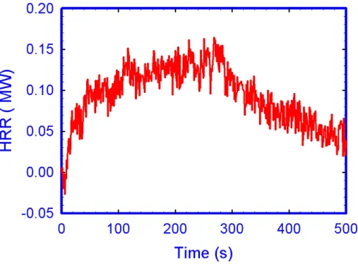
Four pans for pool fires were made from 6 mm thick mild steel and will be used in the fire test program. The sizes of pans are: 0.3 m x 0.3 m, 0.6 m x 0.6 m, 1.0 m x 1.0 m and 1.0 m x 2.0 m. Depth of these pans is 0.1 m. Heat release rates of three gasoline pool fires with size of 0.3 m x 0.3 m, 0.6 m x 0.6 m and 1.0 m x 1.0 m were measured and are shown in Figures 12 to 14. The heat release rates were determined using a calorimeter system with O2,
CO and CO2 concentrations measured. The heat release rates were verified with weight loss
measurements. For the pool fires with gasoline, there was a rapid fire growth. The maximum heat release rates of these pool gasoline fires are listed in Table 2.
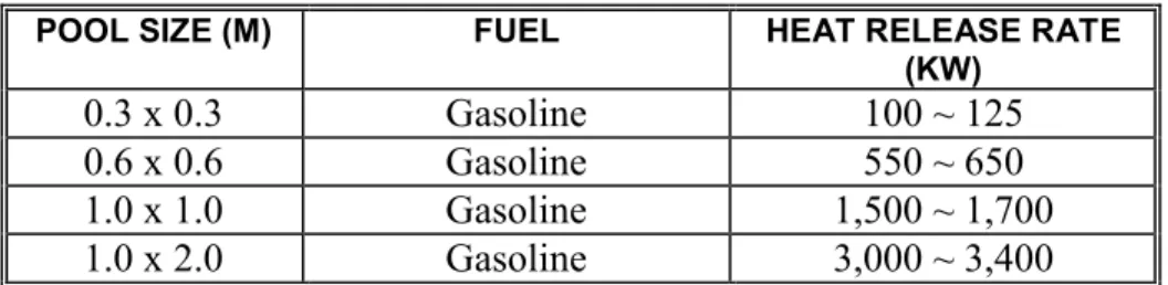
Table 2. Heat Release Rates of Pool Gasoline Fires
POOL SIZE (M) FUEL HEAT RELEASE RATE
(KW)
0.3 x 0.3 Gasoline 100 ~ 125 0.6 x 0.6 Gasoline 550 ~ 650 1.0 x 1.0 Gasoline 1,500 ~ 1,700 1.0 x 2.0 Gasoline 3,000 ~ 3,400
A mock-up that simulates an engine compartment of the vehicle was constructed. Its structure and dimensions are shown in Figure 15. An apparatus that provides a gasoline pool fire with a controlled growth rate was placed inside the compartment and generates an engine compartment fire. It consists of a pan and a movable lid that is moved by a winch apparatus (Figure 16). During tests, the heat release rate of the engine compartment fire and its growth rate can be controlled by increasing the size of the opening of the pan (Figure 17). Figure 18 shows the heat release rate of the growing fire for a 250 mm/min winch speed. It takes approximately 320 s for the fire to reach a heat release rate of 1,600 kW.
A mock-up that simulates the front portion of a vehicle passenger compartment was also constructed. Its structure and dimensions are shown in Figure 19. Wood cribs were placed inside the compartment and used to generate a passenger compartment fire. A number of pans containing alcohol were placed underneath the wood crib and used as the ignition source. The growth rate of the passenger compartment fire can be controlled by the number of alcohol ignition pans and their location underneath the wood crib. Figure 20 shows a simulated passenger compartment fire with three alcohol ignition pans. The heat release rate achieved in this case is shown in Figure 21. It takes approximately 300s for the simulated passenger compartment fire to reach its maximum heat release rate of 1,100 kW.
A mock-up that simulates a moving vehicle fire was also constructed. The fire source consists of a square or rectangular pad of silicon and aluminum oxide fiber blanket soaked with a preset quantity of gasoline. After ignition, the fire source is dragged by a cable using a high speed winch apparatus. Different movement speeds for the fire source can be achieved using this apparatus.
In order to satisfy safety requirements in the field fire tests (Task 4) to be conducted in an operating tunnel, a propane burner system was constructed (Figure 22). The burner system is H-Shaped and has two 2 m long outer legs that are 1.22 m apart, simulating flames from two sides of a vehicle. It has a smoke basket located at the center of the burner so that hot artificial smoker can be produced using smoke bombs. The heat release rate can also be controlled by adjusting the propane flow rate. The heat release rate of the burner has been calibrated and is shown in Figure 23. The burner system can generate a fire of up to 4 MW. The flames and smoke with controlled fire size and growth rate generated from the burner system can avoid potential damages to the tunnel, and at the same time, provide a fire source for the field tests.
Figure 12. Heat release rate of 0.09 m2 pool gasoline fire
Figure 14. Heat release rate of 1.0 m2 pool gasoline fire
Figure 16. Schematic of a pool pan for a controlled growing fire
Figure 18. Variation of the heat release rate of a simulated engine compartment fire with time at 25 cm/min of the lid winch moving speed
Figure 20. A simulated passenger compartment fire generated in a test
Figure 22. A propane burner fire with controlled heat release rate
7. INSTRUMENTATIONS
Various instruments (Figure 24) will be used to monitor fire tests in the present project. They include:
• Thermocouples (Type K, 18 gauge, Figure 24f) will be distributed in the tunnel for temperature measurements. These include thermocouples located at the ceiling of the tunnel facility as well as thermocouple drops. Thermocouples will also be located near the detectors.
• Two smoke meters (Figure 24d) will be used for measuring smoke optical density in the tunnel. They will be located approximately 12 m from the fire source: one pulsed white light smoke meter in the hot layer and one laser smoke meter with the laser near the ground and the laser beam from floor to ceiling.
• Two velocity meters (Figure 24a) will be used to measure the air velocity in the tunnel. They will be located approximately 12 m from the fire source: one in the upper portion of the tunnel and one in lower portion of the tunnel. • A number of heat flux meters and radiometers (Figure 24b) will be located
near the fire source and distributed in the tunnel to measure the heat and radiant flux of the fire, and to monitor the fire development.
• A number of regular Sony Hi8 digital video cameras (Figure 24e) will be used to provide a video record for the tests.
The locations and distributions of these instrumentations will remain unchanged in the test program. However, some changes on the instrumentations will be made from the laboratory fire test program (Task 2) to the field fire test program (Task 4). Test data will be collected at 1 second intervals by a data acquisition system (Figure 24c).
8. SUMMARY
The activities comprising Task 1 of the tunnel detection research program have been completed and the results are summarized in this report. They are:
• Selection of ten fire detection systems for use in the fire test program; • Preparation of requirements for design and installation of the detection
systems in the test program;
• Identification of performance parameters for the detection systems that will be measured in the test program;
• Development of fire scenarios for use to investigate the performance of tunnel fire detection systems;
• Construction of mock-ups and fire sources for use in the test program and measured their heat release rates;
• Development of instrumentation for use in the Laboratory tunnel tests; and • Proposal of a test plan for the Laboratory tunnel tests (Task 2, see Appendix I).
Figure 24 a). Velocity meter Figure 24 b). Heat flux
Figure 24 c). Data Collection system
Figure 24 d). Smoke meters
Figure 24 e). Video Camera Figure 24 f). Thermocouple Figure 24. Some instrumentation in the test program
REFERENCES
1. Zalosh, R and Chantranuwat, P., “International Road Tunnel Fire Detection Research Project, Phase 1: Review of Prior Test Programs and Tunnel Fires,” The Fire Protection Research Foundation, November 2003.
2. Ishii, H., Kawamura, K., Ono, T., Megumi, H. and Kikkawa, A., “A fire detection system using optical fibres for utility tunnels,” Fire Safety J. 29 (1997) 87-98.
3. Mashimo, H., “State of the Road Tunnel Safety Technology in Japan,” Tunnelling and Underground Space Technology, 17 (2002) 145-152.
4. Capaul, T., “Evaluation linear temperature sensor response testing in Mositunnel, Switzerland, June 11-12, 1992,” Cerberus Report, 1992.
5. Magerle, R., “Fire Protection Systems for Traffic Tunnels Under Test,” Proceedings AUBE 01 Conference, NIST, 2001.
6. Webb, K., “Hot Smoke Tests in the South East Transit Project Busway Tunnel Section 1B – Ernest Street and Water Street,” BCE Doc. 00/351, CSIRO, September 2000.
7. Unpki, J. and Kimura, S., “New Fire Detector for Road Tunnels,” Fire Safety Journal, P.215-224, 6, 1983.
8. Azuma, T., Gunki, S., Ichikawa, A. and Yokota, M., “Effectiveness of a Flame Sensing Type Fire Detector in a Large Tunnel,” 6th International Conference on Safety in Road and Rail Tunnels, Marseilles, France, October 2004
9. Brugger, S. “Rapid Fire Detection Concept for Road Tunnels,” 5th International Conference on Safety in Road and Rail Tunnels, Marseilles, France, October 2004 10. Wieser, D. and Brupbacher, T., “Smoke Detection in Tunnels Using Video Images,”
Proceedings AUBE 01 Conference, NIST, 2001.
11. Versavel, J. and Collins, S., “Automatic Incident Video Detection: the Standard its Technology Today for Traffic and Tunnel Safety,” 6th International Conference on Safety in Road and Rail Tunnels, Marseilles, France, October 2004.
12. FIT European Thematic Network, “Fire Safety Design – Road Tunnel” Draft 2, September 2003
13. NFPA 502, “Standard for Road Tunnels, Bridges, and other Limited Access Highways,” National Fire Protection Association, 2004
14. U.S. Department of Transportation, Federal Highway Administration, “Prevention and Control of Highway Tunnel Fires,” FHWA-RD-83-032, 1984.
15. PIARC Committee on Road Tunnels (C5), “Fire and Smoke Control in Road Tunnels,” World Road Association, ISBN 2-84060-064-1, 1999
16. Germany/RABT 02, “Guidelines for Equipment and Operation of Road Tunnels,” 2002
17. Ingason, H. Lonnermark, A., “Recent Achievements Regarding Measuring of Time-Heat and Time Temperature Development in Tunnels,” 1st International Symposium on Safe & Reliable Tunnels, Prague, April 2004.
18. R.O. Carvel, A.N. Beard, P.W. Jowitt, and D.D. Drysdale, “The Influence of Tunnel Geometry and Ventilation on the Heat Release Rate of a Fire,” Fire Technology, 40, 5-26, 2004
19. International Association of Arson Investigators, Alberta Chapter, “A study of vehicle fires of known ignition source,” Jan. 1983
20. R. Hrynchuk, “CAFI vehicle fire investigation techniques, A report on Vehicle Fire Tests,” Canadian Association of Fire Investigators Seminar, Sept. 30, 1998, Toronto, Ont.
21. J. Mangs and O. Keski-Rahkonen, “Characterization of the Fire Behaviour of a Burning Passenger Car, Part I: Car Fire Experiments,” Fire Safety Journal 23 (1994) 17-35
22. J. Mangs and O. Keski-Rahkonen, “Characterization of the Fire Behaviour of a Burning Passenger Car, Part II: Parametrization of Measured Rate of Heat Release Curves,” Fire Safety Journal 23 (1994) 37-49
Appendix I
Test Plan for Task 2 of the Tunnel Fire Detection Project
(Phase II) – Laboratory Tunnel Fire Tests
A series of full-scale fire tests will be conducted in a new Carleton University tunnel facility located adjacent to the National Research Council Canada (NRCC) full-scale fire test facilities. The fire detection systems will be installed in the research tunnel and their capabilities to detect the test fires will be investigated using various tunnel fire scenarios. Task 2 will also provide information for carrying out Task 4 of the project in which fire tests will be conducted in an operating road tunnel in the city of Montreal.
The dimension of the tunnel facility is 10 m wide x 5.5 m high x 37 m long (30 ft x 16.5 ft x 113 ft long). Natural ventilation will be maintained during the fire tests (note: the effects of ventilation on the performance of fire detection systems will be studied in a future Phase of the program). General description and requirements for fire detection systems, and fire scenarios in the test program are provided in this report.
1 Fire Detection Systems
Ten fire detection systems representing five types of available technologies were selected and will be evaluated in the full-scale fire tests. They are listed in Table 1.
Appendix Table 1. Fire Detection Systems in the Test Program Technology System no. System information
D-1L1 Fibre optic linear heat detection system
Linear heat
D-2L2 Analogue (co-axial cable) linear heat detection system
D-3F1 IR3 flame detector
Flame
D-4F2 Multi-IR flame detector
D-5C1 Visual based fire and smoke detection system D-6C2 FDS-101 visual flame detector
CCTV
D-7C3 Visual fire detection system
D-8H1 Heat detector with a fixed temperature
Spot heat
D-9H2 Rate-Anticipation heat detector
Smoke D-10S1 Air sampling-type system
All the selected fire detection systems will be installed in the tunnel facility by the manufacturers and evaluated under the same fire tests. Their installation configurations will not be changed during the test program.
The configuration and installation of the fire detection systems in the tunnel facility will be designed based on a road tunnel with a dimension of 10 m wide x 5.5 m high x 2,000 m long (30 ft x 16.5 ft x 6,100 ft long). The sensitivity level of the fire detection systems used in the laboratory tunnel fire tests will be the same as those used in the environment tests in the Lincoln tunnel of the Port Authority in Tasks 5 and 6 of the project.
The total length of the sensing cable of linear heat detection systems used in the tests will be the maximum sensing length of the system. The cable installed on the ceiling of the tunnel facility will be at the maximum sensing length of the system recommended by the manufacturer.
Flame detectors will be installed on the wall of the tunnel. The distance from the detector to the fire source will be the lesser of 31 m (100 ft), or the maximum distance recommended by the manufacturer. The installation of the detectors will be such that their field of view covers the entire tunnel.
CCTV fire detectors will be installed on the wall of the tunnel. The distance from the detector to the fire source will be the lesser of 31 m (100 ft), or the maximum distance recommended by the manufacturer. The installation of the detectors will be such that their field of view covers the entire tunnel.
Spot heat detectors will be installed on the ceiling of the tunnel. The fire source will be located at a point equidistant from the two nearest detectors.
Air sampling pipes of the smoke detection system will be installed on the ceiling of the tunnel. The fire source will be located near the end of a zoned pipe network.
The performance of fire detection systems in detecting, locating and monitoring a fire incident will be evaluated using selected tunnel fire scenarios.
2 Fire Scenarios
Four series of fire tests will be conducted in the program. They are: pool fires underneath a vehicle; pool fires behind a large vehicle; stationary vehicle fires; and moving fires.
2.1 Pool Fires underneath the Vehicle
Seven fire tests, as shown in Table 2, will be conducted. Test F2-1P1 is an open fire test without obstacles surrounding the fire source. It will be used to investigate the impact of obstacles on the performance of fire detection systems. The pool fire will be varied approximately from 100 KW to 3,400 kW.
Tests F2-6P1 and F2-7P1 are tests in which a propane burner will be used to simulate fires underneath a vehicle. The information obtained from these tests with the propane burner will be used to develop the fire tests for Task 4 of the project.
Appendix Table 2. Fire Tests in Pool Fire Scenario I TEST NO POOL SIZE
(M)
FUEL HEAT RELEASE
RATE (KW) F2-1P1 0.3 x 0.3 no obstacle Gasoline 100 ~ 125 F2-2P1 0.3 x 0.3 Gasoline 100 ~ 125 F2-3P1 0.6 x 0.6 Gasoline 550 ~ 650 F2-4P1 1.0 x 1.0 Gasoline 1,500 ~ 1,700 F2-5P1 1.0 x 2.0 Gasoline 3,000 ~ 3,400 F2-6P1 A burner Propane 1,500 ~ 1,700 F2-7P1 A burner Propane 3,000 ~ 3,400
2.2 Open Fires behind a Large Vehicle
Four fire tests, as shown in Table 3, will be conducted with gasoline pool fires. The fire size will be varied approximately from 100 KW to 3,400 kW.
Appendix Table 3. Fire Tests in Pool Fire Scenario II TEST NO POOL SIZE
(M)
FUEL HEAT RELEASE
RATE (KW)
F2-8P2 0.3 x 0.3 Gasoline 100 ~ 125
F2-9P2 0.6 x 0.6 Gasoline 550 ~ 650
F2-10P2 1.0 x 1.0 Gasoline 1,500 ~ 1,700 F2-11P2 1.0 x 2.0 Gasoline 3,000 ~ 3,400
2.3 Stationary Vehicle Fires
Three stationary vehicle fire tests will be conducted in the program, as listed in Table 4. Test F2-12S1 is an engine compartment fire scenario. The heat release rate of the fire will be similar to one generated in a real vehicle engine compartment fire. It will take approximately 8 minutes for the vehicle engine compartment fire to reach its maximum heat release rate (2 MW). Test F2-13S1 is also an engine compartment fire scenario. The test conditions are the same as Test F2-12S1 except a propane burner will be used. The information obtained from this test will be used to develop the fire tests for Task 4 of the project.
Test F2-14S1 is a passenger compartment fire scenario. Wood cribs will be used to simulate a passenger compartment fire. An alcohol pan fire placed underneath the wood crib will be used as the ignition source. It will take approximately 10 minutes for the fire to reach its maximum heat release rate (1.1~ 1.5MW).
Appendix Table 4. Fire Tests in Stationary Vehicle Fire Scenarios TEST NO FIRE SCENARIO FUEL HEAT RELEASE
RATE (KW)
F2-12S1 Engine compartment Gasoline 2,000
F2-13S1 Engine compartment Propane 2,000
F2-14S1 Passenger compartment Wood crib 1,100 ~ 1,500
2.4 Moving Vehicle Fires
Four fire tests with two different moving speeds and two driving directions relative to the detectors will be conducted, as shown in Table 5. The heat release rate of the moving fire is approximately 100 ~ 150 kW with the fire source at rest.
Appendix Table 5. Moving Vehicle Fire Tests TEST NO FIRE SIZE
(KW) DRIVING SPEED (KM/HR) DRIVING DIRECTION TO FIRE DETECTORS F2-15M1 100~150 20 Facing F2-16M1 100~150 50 Facing F2-17M2 100~150 20 Away F2-18M2 100~150 50 Away 3 Instrumentation
Various instruments will be installed inside the research tunnel to monitor the fire tests. A schematic of instrumentation in the test tunnel is shown in Figure 25.
Appendix Figure 25. Schematic of instrumentation in the test tunnel
Detailed information on the instrumentation is as follows:
• Thermocouples will be distributed in the tunnel for temperature measurements. This includes 55 thermocouples located at the ceiling of the tunnel facility. As shown in Figure 25, the transverse and longitudinal distances between thermocouples on the ceiling of the tunnel are 1.67 m and 3.75 m, respectively. Two thermocouple trees are dropped from the ceiling of the tunnel: one located at the fire position and the other at the middle of the tunnel. There are five thermocouples on each tree: 0.5 m distance from the ground and to the ceiling, and 1.1 m interval distance between the thermocouples. Thermocouples will also be placed near each detector.
• Two smoke meters will be used for measuring smoke concentration in the tunnel, as shown in Figure 25. They will be located at the mid-point of the tunnel: one pulsed white light smoke meter in the hot layer and one laser smoke meter with the laser near the ground and laser beam from the floor to the ceiling.
• Two velocity meters will be used to measure the air velocity in the tunnel, as shown in Figure 25. They will be located at the mid point of the tunnel: one in the upper portion of the tunnel and one in lower portion of the tunnel. • A number of heat flux meters and radiometers will be distributed in the tunnel
to measure the heat and radiant flux of the fire, and to monitor the fire development. They are located, respectively, 1 m, 2 m, 5 m and 10 m from the fire, as shown in Figure 25. One radiometer will also be placed near the end of the tunnel close to the flame detectors.
• Three video cameras will be used to provide video records for the tests. Two digital video cameras will be located at each end of the tunnel and one near the fire location.
The performance (response time and fire locating capability) of the detection systems will be recorded by NRCC using the outputs from the detectors.
4 Test Procedure
The general test procedure will be as follows:
• Check each detection system prior to each test, to assure normal operation, • Start the data acquisition system and video recorders for 60 s, and then
manually ignite the fire, • Terminate the test when:
- All the detectors activate,
- Or 4 minutes after the fire reaches its maximum heat release rate, - Or a maximum safe operating temperature at the ceiling is reached. • Check each detection system to determine if they still function properly after