Publisher’s version / Version de l'éditeur:
Vous avez des questions? Nous pouvons vous aider. Pour communiquer directement avec un auteur, consultez la première page de la revue dans laquelle son article a été publié afin de trouver ses coordonnées. Si vous n’arrivez pas à les repérer, communiquez avec nous à [email protected].
Questions? Contact the NRC Publications Archive team at
[email protected]. If you wish to email the authors directly, please see the first page of the publication for their contact information.
https://publications-cnrc.canada.ca/fra/droits
L’accès à ce site Web et l’utilisation de son contenu sont assujettis aux conditions présentées dans le site
LISEZ CES CONDITIONS ATTENTIVEMENT AVANT D’UTILISER CE SITE WEB.
Research Report (National Research Council of Canada. Institute for Research in
Construction), 2005-05-19
READ THESE TERMS AND CONDITIONS CAREFULLY BEFORE USING THIS WEBSITE.
https://nrc-publications.canada.ca/eng/copyright
NRC Publications Archive Record / Notice des Archives des publications du CNRC :
https://nrc-publications.canada.ca/eng/view/object/?id=a3eb57c3-04cb-4231-b2ad-e99c62dc9684 https://publications-cnrc.canada.ca/fra/voir/objet/?id=a3eb57c3-04cb-4231-b2ad-e99c62dc9684
NRC Publications Archive
Archives des publications du CNRC
For the publisher’s version, please access the DOI link below./ Pour consulter la version de l’éditeur, utilisez le lien DOI ci-dessous.
https://doi.org/10.4224/20377739
Access and use of this website and the material on it are subject to the Terms and Conditions set forth at
Full-Scale Fire Study of Spatial Separation
FULL-SCALE FIRE STUDY
OF SPATIAL SEPARATION
Research Report: IRC-RR-195
Date of Issue: May 19, 2005
Authors: Joseph Z. Su and Bruce C. Taber
Published by
Institute for Research in Construction National Research Council Canada Ottawa, Canada
FULL-SCALE FIRE STUDY OF SPATIAL SEPARATION
By
Joseph Z. Su and Bruce C. Taber Fire Research Program Institute for Research in Construction National Research Council of Canada
ABSTRACT
With rising land and infrastructure costs and the demand for affordable housing, there is increasing pressure to allow new houses be built closer together. A series of full-scale fire experiments were conducted to provide data to address spatial separation issues and measures to limit potential fire spread between adjacent houses. Wall assemblies with different exterior finishing (exterior gypsum board, aluminum siding on waferboard sheathing, or waferboard) were positioned at various wall-to-wall and eave-to-eave separation distances. The fire
compartment contained a fuel package of wood mixed with ABS plastic pipes comprising a fuel load of 16.9 kg per square meter of the floor area. Flame issued from the fire compartment through a rough opening on the exposing wall. Results showed the need for maintaining adequate spatial separation, including eave separation. Aluminum claddings on combustible sheathing or gypsum board as exterior sheathing, showed its effectiveness in reducing the danger of fire spread between houses built at a close distance and provided protection against fire spread for a period within the typical response time of a fire department. Blocking attic ventilation through eaves adjacent to neighbouring houses appeared to be another measure to reduce the fire spread potential.
TABLE OF CONTENTS
ABSTRACT ... i
1.0 INTRODUCTION... 1
2.0 FIRE EXPERIMENTS ... 1
2.1 Test 1... 2
2.1.1 Experimental Set-up of Test 1 ... 2
2.1.2 Experimental Results of Test 1... 3
2.2 Test 2... 4
2.2.1 Experimental Set-up of Test 2 ... 4
2.2.2 Experimental Results of Test 2... 4
2.3 Test 3... 5
2.3.1 Experimental Set-up of Test 3 ... 5
2.3.2 Experimental Results of Test 3... 5
3.0 SUMMARY... 6
4.0 ACKNOWLEDGEMENTS ... 7
LIST OF FIGURES Figure 1 Two-storey wall assemblies for full-scale fire experiments ... 8
Figure 2 Partial roof with asphalt shingles... 8
Figure 3 Drawing of fire compartment ... 9
Figure 4 Mixed fuel package of wood cribs and plastic pipes ... 9
Figure 5 Construction detail of wall assemblies for Test 1 ... 10
Figure 6 Photographs of wall assemblies constructed for Test 1 ... 11
Figure 7 Instrumentation for Test 1 ... 12
Figure 8 Photographs during Test 1 ... 13
Figure 9 Temperature profiles for Test 1 ... 14
Figure 10 Heat flux profiles for Test 1 ... 15
Figure 11 Photographs of wall assemblies after Test 1... 16
Figure 12 Construction detail of wall assemblies for Test 2 ... 17
Figure 13 Photographs of wall assemblies constructed for Test 2 ... 18
Figure 14 Instrumentation for Test 2 ... 19
Figure 15 Six heat flux meters (black discs) on wall assemblies for Test 2 ... 20
Figure 16 Photographs during and after Test 2... 21
Figure 17 Temperature profiles for Test 2 ... 22
Figure 18 Heat flux profiles for Test 2 ... 23
Figure 19 Construction detail of wall assemblies for Test 3 ... 24
Figure 20 Photograph of wall assemblies constructed for Test 3 ... 25
Figure 21 Instrumentation for Test 3 ... 26
Figure 22 Photographs during Test 3 ... 27
Figure 23 Temperature profiles for Test 3 ... 28
Figure 24 Heat flux profiles for Test 3 ... 29
FULL-SCALE FIRE STUDY OF SPATIAL SEPARATION
Joseph Z. Su and Bruce C. Taber
Fire Research Program, Institute for Research in Construction National Research Council of Canada
1.0 INTRODUCTION
With rising land and infrastructure costs and the demand for affordable housing, there is increasing pressure to allow new houses be built closer together. The National Research Council of Canada (NRC) undertook an experimental program to study spatial separation issues for the City of Calgary and the Safety Codes Council. The objective was to provide technical data to address increased housing density while maintaining the necessary spatial separation to limit potential fire spread between houses in case of a fire. This report documents the results of a series of full-scale fire experiments conducted in the NRC fire research facility at Almonte, ON.
2.0 FIRE EXPERIMENTS
Three full-scale fire experiments were conducted using 2-storey wall assemblies, as shown in Figure 1. In each experiment, a target wall assembly faced an exposing wall assembly at a given spatial separation. The exposing wall assembly had a rough window opening and was part of a fire compartment. Flame extension from the fire compartment opening towards the target (or exposed) wall assembly, as well as effect of eaves on fire spread, were investigated.
Three exposing and 3 target wall assemblies were constructed, as per the specifications provided by the City of Calgary. Each wall had a wood frame of 3.66 m wide and 4.93 m high with 400 mm (16") stud spacing and insulated with R20 Batt insulation (the stud spacing should have no effect on the assembly performance as far as exterior fire spread is concerned). The interior side of each wall was lined with 6 mil vapour barrier and 12.7 mm (½") interior drywall. The exterior side of each wall was finished with different sheathing on building paper (specific sheathing for each experiment is described in the following subsections). Each wall had an aluminum soffit and partial asphalt roof (Figure 2). The asphalt shingle roof with building paper and 7/16" waferboard sheathing had a slope of 7:12. The total height of each wall assembly was 4.56 m.
The fire compartment was 2.95 m wide, 2.51 m high and 3.00 m deep, as shown in Figure 3. A lintel depth above the rough window opening was 0.38 m. In addition to the rough window opening on the exposing wall, there were 2 side-access openings with dimensions of 0.40 m wide and 1.20 m high. The fire compartment was lined with gypsum boards. A spray nozzle was installed at the centre of the ceiling and connected to a charged water line as a means for fire extinguishment.
A mix of wood and plastic was placed in the fire compartment as a fuel package, containing 100-kg spruce (2" x 4") and 50-kg acrylonitrile butadiene styrene (ABS)
thermoplastics pipes. Figure 4 shows the fuel package used in each fire experiment. The spruce sticks were arranged in 2 wood cribs and the ABS pipes were put on top of the cribs. The fuel load was 16.9 kg per square meter of the floor area of the fire compartment. A total of 600 mL methanol was put in 3 pans and placed beneath the cribs as an ignition source.
A thermocouple tree was placed in the fire compartment to measure the flame
temperatures, with 4 thermocouples vertically distributed at 0.53, 1.07, 1.60 and 2.13 m above the floor. Three thermocouples were installed at the top of the rough window opening, with 0.30 m spacing. Additional thermocouples were also installed above soffits and in attic spaces of both target and exposing wall assemblies for temperature measurement. Heat flux was measured on both walls.
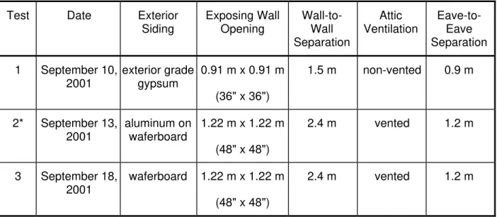
Table 1 shows a matrix of the fire experiments. Exact exterior finish, attic ventilation condition, rough opening and spatial separation of the wall assemblies and instrumentation for each experiment are given in the following subsections. Each experiment was videotaped from 3 different viewpoints (the exposing wall, target wall and space in-between). The experiment procedure was as follows:
1. Verification of experiment layout, instrumentation and data acquisition; 2. Starting data acquisition system;
3. Igniting fuel;
4. Observation of fire development;
5. Ending the experiment by actuating water spray to extinguish the fire.
Table 1 – Matrix of Full-Scale Fire Experiments
Test Date Exterior Siding Exposing Wall Opening Wall-to-Wall Separation Attic Ventilation Eave-to-Eave Separation 1 September 10, 2001 exterior grade gypsum 0.91 m x 0.91 m (36" x 36") 1.5 m non-vented 0.9 m 2* September 13, 2001 aluminum on waferboard 1.22 m x 1.22 m (48" x 48") 2.4 m vented 1.2 m 3 September 18, 2001 waferboard 1.22 m x 1.22 m (48" x 48") 2.4 m vented 1.2 m
* The target wall has a fireplace chase with projection of 0.6 m.
2.1 Test
1
2.1.1 Experimental Set-up of Test 1
Figure 5 shows the construction detail for the wall assemblies. The exterior of both exposing and target walls was finished with exterior grade gypsum boards. The exterior gypsum sheathing was extended up to the underside of the roof sheathing, blocking ventilation
into the roof cavity. The aluminum soffit had a 0.3 m eave extension at the top of both walls. The rough window opening on the exposing wall was 0.9 m x 0.9 m. Physical separation of the two wall assemblies was 1.5 m wall-to-wall and 0.9 m eave-to-eave. Figure 6 shows
photographs of the wall assemblies.
Figure 7 shows the instrumentation detail for Test 1. In addition to the thermocouple tree in the fire compartment and 3 thermocouples at the top of the rough opening, 4
thermocouples were installed in the roof area of each wall assembly (2 above the soffit and 2 in the attic space). Heat flux was measured on both walls to obtain information on heat transfer by convection and radiation. Three heat flux meters were installed on the target wall at heights of 2.1 m (facing the top of the rough opening), 3.1 m and 4.8 m (below the soffit) along the vertical central line. Two heat flux meters were installed on the exposing wall at heights of 3.1 m and 4.8 m along the vertical central line.
2.1.2 Experimental Results of Test 1
Figure 8 shows photographs during the fire experiment. The experiment ran over 15 min, starting from ignition. After ignition, the compartment fire was developed. Flame started to come out of the fire compartment from the very top of the rough opening 2 min 10 s after ignition. Flashover took place at 2 min 40 s when the temperature of the upper part of the compartment went well beyond 600°C and flame was fully issued from the rough opening. (Flame and smoke were also issued from the 2 side-access openings.) Figure 9 shows temperature profiles measured at various locations during the fire experiment. After flashover, the compartment fire was further developed, the upper room temperatures increased to above 1000°C and the rough opening temperatures increased to around 800°C.
Two minutes after the flashover, flame issued from the fire compartment started to impinge on the target wall, as shown in Figure 8. It was observed that the drywall paper on the target wall surface had a few moments of brief flare along the flame contacting area but never had sustained burning. Figure 10 shows profiles of heat fluxes measured at both target and exposing walls. For many combustible materials, the critical heat flux values are 12 kW/m2 for piloted ignition and 25 kW/m2 for non-piloted ignition. The heat fluxes measured on the target wall all exceeded these 2 critical values, with the highest heat flux measured at the 3.1 m
height. The peak heat flux on the target wall was 48, 87 and 40 kW/m2 at the 4.8, 3.1 and 2.1 m heights, respectively. A 12-min average heat flux was 14 kW/m2 at the 4.8 m height, 26 kW/m2 at the 3.1 m height, and 26 kW/m2 at the 2.1 m height on the target wall. Although these heat fluxes were high enough for ignition of many combustible materials, the exterior drywall successfully prevented the ignition of the target wall assembly.
The heat flux to the exposing wall at 4.8 m was 10 kW/m2 at its peak and 5 kW/m2 for its 12-min average. The heat flux to the exposing wall at 3.1 m had a peak value of 63 kW/m2 and a 12-min average of 17 kW/m2, which were much higher than at 4.8 m.
Since the exterior gypsum drywall was extended up to the roof to block attic ventilation, the temperature in the roof attic was much lower than that in the soffit cavity for both target and exposing wall assemblies.
The experiment ended 15 min 10 s after the ignition by actuating water spray to
extinguish the fire. Figure 11 shows both the exposing and target wall assemblies after the fire experiment. The target wall had only surface damage in the flame impinging area (the top part
near the soffit was not damaged). The exterior drywall also prevented fire from spreading upwards along the exposing wall. Although darkened by the smoke, the soffits on both wall assemblies were well intact except that one small piece on the target soffit was slightly deformed.
2.2 Test
2
2.2.1 Experimental Set-up of Test 2
Figure 12 shows the construction detail for the wall assemblies. The exterior of both exposing and target walls was finished with aluminum siding on waferboard sheathing. The aluminum soffit was vented and had a 0.6 m eave extension at the top of both walls. The target wall had a 1.2 m wide fireplace chase with a projection of 0.6 m towards the exposing wall. The rough window opening on the exposing wall was 1.2 m x 1.2 m. The rough opening of the exposing wall was centered on one edge of the fireplace chase of the target wall. This was to ensure that both the fireplace extension and the target main wall would be exposed to the flame from the fire compartment opening. Physical separation of the 2 wall assemblies was 1.2 m from eave to eave, 1.8 m from the exposing wall to the fireplace chase on the target wall, and 2.4 m from the exposing wall to the target wall. Figure 13 shows photographs of the wall assemblies.
Figure 14 shows the instrumentation detail for Test 2. In addition to the thermocouple tree in the fire compartment and 3 thermocouples at the top of the rough opening, 4
thermocouples were installed in the roof area of each wall assembly (2 above the soffit and 2 in the attic space). Six heat flux meters were installed on the fireplace chase, the target and exposing walls at heights of 3.1 m and 4.8 m. The 2 heat flux meters on the exposing wall were installed along the vertical central line. The 4 heat flux meters on the target wall were installed along the edge of the fireplace chase and the inside corner between the target wall and the jog. Figure 15 shows photographs of the 6 heat flux meters installed on the wall assemblies (appear as black discs).
2.2.2 Experimental Results of Test 2
Figure 16 shows photographs during and after the fire experiment. Figure 17 shows temperature profiles measured at various locations during the fire experiment. The experiment ran over 15 min starting from ignition.
Flame started to come out of the fire compartment from the very top of the rough opening 2 min 20 s after ignition and flashover took place at 2 min 30 s. (Smoke was also issued from the 2 side-access openings.) The upper compartment temperatures further increased to above 1000°C and the rough opening temperatures increased to around 1100°C after flashover.
During the first 3 minutes since flashover, flame issued from the rough opening projected more upwards without touching the target wall assembly. As shown in Figure 18, the exposing wall assembly received more heat flux than the target wall assembly did. The heat flux on the exposing wall at the 3.1 m height reached 50 kW/m2. A 12-min averaged heat flux was 28 kW/m2 at the 3.1 m height of the exposing wall. The aluminum siding above the exposing
wall opening was partially deformed, which led the flame and hot gases to get in-between the aluminum siding and waferboard. It was observed that the exposing wall surface was burning (near the 3 m height). Some hot gases got into the roof space of the exposing assembly through the ventilated soffit, as indicated by the temperatures shown in Figure 17.
Three minutes after the flashover, flame issued from the fire compartment started to impinge on the fireplace chase surface of the target assembly, as shown in Figure 16. The heat flux to the fireplace chase reached a peak of 26 kW/m2 at the 3.1 m height. A 12-min average heat flux was 16 kW/m2 at the 3.1 m height of the fireplace chase.
Flame issued from the rough opening never touched the portion of the target wall that was 2.4 m away from the exposing wall. The peak heat flux received by this portion of the target wall was 13 kW/m2 at the 3.1 m height. The heat flux reading at the top (4.8 m height) of the target wall, the fireplace chase or the exposing wall was lower than that at the 3.1 m height. The temperatures in the target wall roof space were not significant.
After being exposed to the flame from the fire compartment for more than 12 min, the target wall assembly still stood well. The experiment was ended 15 min 10 s after the ignition by actuating water spray to extinguish the fire in the fire compartment. As shown in Figure 16, the target assembly had soot deposition on the soffit and upper part of the wall but no thermal damage. The aluminum siding effectively protected the combustible waferboard sheathing behind it. For the exposing wall assembly, the aluminum siding was burnt through right above the rough opening with a triangular shaped hole and upper part of the siding was deformed. The soffit of the exposing wall was darkened with soot but still intact.
2.3 Test
3
2.3.1 Experimental Set-up of Test 3
Figure 19 shows the construction detail for the wall assemblies. The exterior of both exposing and target walls was finished with waferboard only. The aluminum soffit was vented and had a 0.6 m eave extension at the top of both walls. The rough window opening on the exposing wall was 1.2 m x 1.2 m. Physical separation of the two wall assemblies was 2.4 m wall-to-wall and 1.2 m eave-to-eave. Figure 20 shows a photograph of the wall assemblies.
Figure 21 shows the instrumentation detail for Test 3, which is similar to the
instrumentation used in Test 1. In addition to the thermocouple tree in the fire compartment and 3 thermocouples at the rough opening, 4 thermocouples were installed in the roof area of each wall assembly. Three heat flux meters were installed on the target wall at heights of 2.1 m, 3.1 m and 4.8 m along the vertical central line. Two heat flux meters were installed on the exposing wall at heights of 3.1 m and 4.8 m along the vertical central line.
2.3.2 Experimental Results of Test 3
The experiment started with ignition of the fuel inside the fire compartment. Figure 22 shows photographs during the fire experiment. Flame started to come out of the fire
compartment from the very top of the rough opening at 2 min 37 s. Flashover took place at 2 min 50 s when the temperature of the upper part of the compartment went well beyond 600°C.
Flame was fully issued from the rough opening and also spread upwards along the exposing wall waferboard. The exposing wall above the rough opening was ignited and started to burn at 3 min 18 s. Flame continued to spread upwards and impinged on the soffit of the exposing assembly at around 3 min 50 s. Fire was spread into the attic space of the exposing assembly at 4 min. In the subsequent 2 minutes, the exposing wall assembly (including its exterior
surface, soffit and attic space) was fully burning; fire plume and hot gases filled the upper space in-between the 2 wall assemblies. The target wall was exposed to both the flame issued from the fire compartment and the additional heat being generated by the fire under the soffit in the exposing wall. The flame started to impinge on the soffit of the target assembly at around 4 min 40 s and touched the target wall at around 5 min 7 s.
As shown in Figure 23, temperatures reached 1100°C at the upper part of the fire compartment, 1150°C at top of the rough opening, and over 900°C in the roof space of the exposing wall assembly. The heat flux readings on the exposing wall were as high as
120 kW/m2 at the 4.8 m height and 150 kW/m2 at the 3.1 m height, as shown in Figure 24. The heat fluxes to the target wall were 23, 21 and 29 kW/m2 at the 2.1, 3.1 and 4.8 m heights. The temperatures in the target roof space were 100–140°C at that time (much higher than in Test 2). It was observed that a substantial amount of steam was coming out of the surface of the target wall. (Note: at the request of the representative of the City of Calgary, the experiment ended at 6 min and water spray was actuated to extinguish the fire in the fire compartment and on the exposing wall assembly.)
Figure 25 shows the exposing and target wall assemblies after the fire experiment. It was observed that the waferboard and attic of the exposing wall assembly were charred and the soffit on the exposing assembly was totally destroyed. Although the target wall assembly was not yet ignited, certain thermal damage was observed on the waferboard and the soffit of the target wall assembly.
NRC replicated this experiment a month later. The ambient temperature was 6°C, which was 11°C lower than the previous month. The experimental set-up was exactly the same except that an unvented aluminum soffit was used for the exposing wall assembly to stop flame getting into the attic space. This experiment was allowed to continue for 15 min. Flashover took place in 4 min. The exposing wall started to burn at 5 min and was fully involved. The unvented aluminum soffit on the exposing wall successfully prevented fire from spreading into the attic space. During the experiment, flame projection from the fire compartment did not reach the target wall. The heat fluxes to the target wall were lower than the previous occasion. The heat flux at the 3.1 m height on the target wall was below 12 kW/m2 (the critical value for piloted ignition) at all times. The heat flux to the target wall at the 4.8 m height was above the critical value for piloted ignition for only 40 s (with a peak of 18 kW/m2). There were about 4 minutes for which the heat flux to the target wall at the 2.1 m height was above the critical value, with a peak of 16 kW/m2. The target wall, however, was not ignited during the experiment while steam was seen coming out of its surface.
3.0 SUMMARY
The full-scale experiments used the fuel package of wood mixed with plastic pipes, which gave a fuel load of 16.9 kg per square meter of the floor area of the fire compartment. In each experiment, fire was developed to the flashover stage in 2.5 to 3 min in the fire
Test 1 was conducted using the two wall assemblies with exterior gypsum board finishing and non-ventilated attic. The exposing wall had a 0.9 m x 0.9 m rough window opening. Physical separation of the two assemblies was 1.5 m wall-to-wall and 0.9 m eave-to-eave. Although heat fluxes to the target wall were high enough for ignition of many combustible materials and although flame issued from the fire compartment impinged on the target wall, the exterior drywall successfully prevented the ignition of the target wall assembly. The exterior drywall also prevented fire from spreading upwards along the exposing wall. Non-ventilated attic spaces prevented the entrance of flame and hot gases. This experiment indicates that exterior gypsum sheathing could prevent potential fire spread between houses built at this close distance within the typical response time of a fire department.
Test 2 was conducted using the two wall assemblies with aluminum siding on waferboard sheathing. The target wall had a fireplace chase projection of 0.6 m and the exposing wall had a rough window opening of 1.2 m x 1.2 m. Physical separation of the two wall assemblies was 1.2 m from eave to eave, 1.8 m from the exposing wall to the fireplace chase, and 2.4 m from the exposing wall to the target wall. The temperatures at the rough opening were higher than that in Test 1. Flame issued from the rough opening impinged on the fireplace chase surface but never touched the farthest wall of the target assembly. After
exposure to the flame issued from the fire compartment for more than 12 min, the target wall assembly still stood well without thermal damage (soot was deposited on the soffit and upper part of the wall). The aluminum siding effectively protected the combustible waferboard sheathing and prevented the target assembly from ignition within the typical fire department response time.
Test 3 was conducted using the two wall assemblies with waferboard finishing only. The exposing wall had a rough window opening of 1.2 m x 1.2 m. Physical separation of the two wall assemblies was 2.4 m wall-to-wall and 1.2 m eave-to-eave. After flashover, the flame issued from the fire compartment quickly spread upward along the waferboard and into the attic space of the exposing assembly within 70 seconds. With the exposing wall assembly fully burning, fire plume and hot gases filled the upper space in-between the 2 wall assemblies. The flame from the exposing assembly impinged on the target soffit and touched the target wall later during the experiment. Although the target wall assembly was not ignited during the short experiment, as the waferboard became dryer and dryer, it was likely to be ignited if the experiment duration was allowed to continue longer.
The results indicate that there must be adequate spatial separation, including eave separation, between neighbouring houses. Without additional measures to limit potential fire spread, houses with unprotected openings in exterior walls should not be built closer together than what would be permitted for neighbouring properties by the National Building Code of Canada.
4.0 ACKNOWLEDGEMENTS
This study was conducted as a joint research project between the National Research Council of Canada, the City of Calgary and the Safety Codes Council. The authors wish to thank George Crampton, Don Carpenter, Cameron McCartney and Vic Fortington for their assistance in the experiments.
Figure 1. Two-storey wall assemblies for full-scale fire experiments.
Fuel Load
116 118
15" for all tests
Ventalation opening both sides of room Total area 10.4 sq.ft.
47 16
5 99
Spatial Separation Tests all dimentions in inches
194
Figure 3. Drawing of fire compartment.
15
see note "B"
Note A.
Exterior gypsum sheathing will extend up to the underside of the roof sheathing
see note "A"
48 36 Wall Separation of 1.5 m Eave Spacing of 0.9 m Unvented Soffit NOTE B: No window opening in exposed walls 144
2X4 Roof Truss @ 24" O.C.
1/2" Ext. Gypsum Board Building Paper
1/2" Interior Drywall 6 mil Vapour Barrier R20 Batt Insulation
2X6 Studs @ 16"O.C. Double 2X6 Top Plate 2X6 Aluminum Clad Fascia
Ashphalt Shingles Building Paper 7/16" waferboard 24 12 194 12 7 37 5 219
4 Heat Flux meter
(both walls) Heat Flux meter (both walls) Heat Flux meter (exposed wall only)
40
12 12 Thermocouples in attic space
Thermocouples above soffit
Thermocouples at top of window opening Thermocouples at room center 12 15 21 21 21 21
all dimentions in inches
Time (min) 0 5 10 15 Tem perat ure ( o C) 0 200 400 600 800 1000 1200 2.1 m 1.6 m 1.0 m 0.5 m above floor Time (min) 0 5 10 15 T e m perature ( o C) 0 100 200 300 400 500 soffit east soffit west attic east attic west Time (min) 0 5 10 15 T e mp era ture ( o C) 0 200 400 600 800 1000 1200 west centre east Time (min) 0 5 10 15 T e m perature ( o C) 0 100 200 300 400 500 soffit west soffit east attic west attic east Target wall roof
Fire compartment Top of rough opening
Exposing wall roof
Time (min) 0 5 10 15 He at F lux ( k W /m 2 ) 0 10 20 30 40 50 60 70 80 90 Time (min) 0 5 10 15 Heat Flu x ( k W /m 2 ) 0 10 20 30 40 50 60 70 80 90 Time (min) 0 5 10 15 He at F lux ( k W /m 2 ) 0 10 20 30 40 50 60 70 80 90 Time (min) 0 5 10 15 Heat Flu x ( k W /m 2 ) 0 10 20 30 40 50 60 70 80 90 Time (min) 0 5 10 15 Heat Flux ( k W /m 2 ) 0 10 20 30 40 50 60 70 80 90
Top on target wall
Mid on exposing wall Top on exposing wall
Bottom on target wall Mid on target wall
Fireplace Chase
Window opening on exposing wall only Fireplace chase on exposed wall only
48 24 15 Aluminum Siding Wall Separation of 2.4 m Eave Spacing of 1.2 m 36 48 48 48 Vented Soffit
all dimentions in inches
144
2X4 Roof Truss @ 24" O.C.
7/16" Waferboard Building Paper
1/2" Interior Drywall 6 mil Vapour Barrier R20 Batt Insulation
2X6 Studs @ 16"O.C. Double 2X6 Top Plate 2X6 Aluminum Clad Fascia
Ashphalt Shingles Building Paper 7/16" waferboard 24 194 12 7 37 5 219
4 EXPOSING WALL
Heat Flux meters on centre line of wall
EXPOSED WALL
Heat Flux meters on wall face and fireplace chase
40
12 12 Thermocouples in attic space
Thermocouples above soffit
Thermocouples at top of window opening Thermocouples at room center 12 15 21 21 21 21
all dimentions in inches
Time (min) 0 5 10 15 T e m p erat u re ( o C) 0 200 400 600 800 1000 1200 2.1 m 1.6 m 1.0 m 0.5 m above floor Time (min) 0 5 10 15 T e m p er atu re ( o C) 0 50 100 150 200 soffit east soffit west attic east attic west Time (min) 0 5 10 15 T e m p erat u re ( o C) 0 200 400 600 800 1000 1200 west centre east Time (min) 0 5 10 15 T e m per atu re ( o C) 0 50 100 150 200 soffit west soffit east attic west attic east Target wall roof
Fire compartment Top of rough opening
Exposing wall roof
Time (min) 0 5 10 15 Heat F lux ( k W /m 2 ) 0 10 20 30 40 50 60 Time (min) 0 5 10 15 He at F lu x ( k W /m 2 ) 0 10 20 30 40 50 60 Time (min) 0 5 10 15 He at F lux ( k W /m 2 ) 0 10 20 30 40 50 60 Time (min) 0 5 10 15 Heat Flux ( k W /m 2 ) 0 10 20 30 40 50 60 Time (min) 0 5 10 15 He at F lu x ( k W /m 2 ) 0 10 20 30 40 50 60 Time (min) 0 5 10 15 He at F lux ( k W /m 2 ) 0 10 20 30 40 50 60
Mid on exposing wall
Top on chimney face Top on exposing wall
Top on target wall Mid on target wall
Mid on chimney face
24 15 see note "B" Wall Separation of 2.4 m Eave Spacing of 1.2 m 36 48 48 48 Vented Soffit NOTE B: No window opening in exposed walls
all dimentions in inches
144
2X4 Roof Truss @ 24" O.C.
7/16" Waferboard Building Paper
1/2" Interior Drywall 6 mil Vapour Barrier R20 Batt Insulation
2X6 Studs @ 16"O.C. Double 2X6 Top Plate 2X6 Aluminum Clad Fascia
Ashphalt Shingles Building Paper 7/16" waferboard 24 194 12 7 37 5 219
4 Heat Flux meter
(both walls) Heat Flux meter (both walls) Heat Flux meter (exposed wall only)
40
12 12 Thermocouples in attic space
Thermocouples above soffit
Thermocouples at top of window opening Thermocouples at room center 12 15 21 21 21 21
all dimentions in inches
Time (min) 0 2 4 6 8 T e m p erat u re ( o C) 0 200 400 600 800 1000 1200 2.1 m 1.6 m 1.0 m 0.5 m above floor Time (min) 0 2 4 6 8 T e m p erat u re ( o C) 0 200 400 600 800 1000 soffit east soffit west attic east attic west Time (min) 0 2 4 6 8 T e m per atu re ( o C) 0 200 400 600 800 1000 1200 west centre east Time (min) 0 2 4 6 8 T e m per a tur e ( o C) 0 50 100 150 200 soffit west soffit east attic west attic east Target wall roof
Fire compartment
Top of rough opening
Exposing wall roof
Time (min) 0 2 4 6 8 Heat F lux ( k W /m 2 ) 0 20 40 60 80 100 120 140 160 Time (min) 0 2 4 6 8 Heat Flux (k W /m 2 ) 0 20 40 60 80 100 120 140 160 Time (min) 0 2 4 6 8 Heat Flux ( k W /m 2 ) 0 10 20 30 40 50 60 Time (min) 0 2 4 6 8 Heat Flux (k W /m 2 ) 0 10 20 30 40 50 60 Time (min) 0 2 4 6 8 Heat F lux ( k W /m 2 ) 0 10 20 30 40 50 60
Top on target wall
Mid on exposing wall Top on exposing wall
Bottom on target wall Mid on target wall