HAL Id: hal-01704398
https://hal.archives-ouvertes.fr/hal-01704398
Submitted on 9 Feb 2018
HAL is a multi-disciplinary open access
archive for the deposit and dissemination of
sci-entific research documents, whether they are
pub-lished or not. The documents may come from
teaching and research institutions in France or
L’archive ouverte pluridisciplinaire HAL, est
destinée au dépôt et à la diffusion de documents
scientifiques de niveau recherche, publiés ou non,
émanant des établissements d’enseignement et de
recherche français ou étrangers, des laboratoires
Achieving Reusability in Visual Simulation of a Parts
Distribution System
Bruno Bachelet, Osman Balci
To cite this version:
Bruno Bachelet, Osman Balci. Achieving Reusability in Visual Simulation of a Parts Distribution
System. Summer Computer Simulation Conference (SCSC), Jul 1999, Chicago, United States.
pp.115-118. �hal-01704398�
ACHIEVING REUSABILITY IN VISUAL SIMULATION
OF A PARTS DISTRIBUTION SYSTEM
Bruno Bachelet and Osman Balci
Department of Computer Science
Virginia Tech
Blacksburg, Virginia 24061-0106, USA
e-mail: [email protected], [email protected]
KEYWORDS
Component-based model development, discrete-event simulation, graphical simulation, object-oriented simulation, parts distribution system, reusability, visual simulation.
ABSTRACT
The purpose of this paper is to illustrate component-based visual simulation model development using the Visual Simulation EnvironmentTM (VSE) software product. Two libraries are presented: clock library and distribution library. The clock library provides reusable model components for representing date and time in the Gregorian calendar. The distribution library provides reusable model components for simulating parts distribution systems. We have developed a VSE model of a parts distribution system of a local company in Blacksburg, Virginia, by way of reusing from the clock and distribution libraries. The simulation project illustrated the value and importance of component-based model develop-ment under the object-oriented paradigm.
1. INTRODUCTION
Component-based development is becoming increas-ingly important (Brown 1996). It increases automation and productivity in simulation model development by enabling: (a) quality and reliability improvements in simulation mod-els, (b) reduced time to develop and test simulation modmod-els, and (c) cost amortization through simulation model compo-nent reuse. Model factories can be established that manufac-ture model components that can be reused by others in the development of a model.
A component-based simulation modeling marketplace can be established so that the customers of the simulation industry can observe large economic benefits such as reduced costs, increased quality, and interoperation. This technology increases the productivity of simulation modelers
programming. It broadens simulation markets for model pro-ducers by enabling: (a) creation of systematically reusable simulation model components, (b) increased simulation model and other software interoperation, and (c) easy adap-tation for use in international markets.
We use the Visual Simulation EnvironmentTM (VSE) software product (Balci et al. 1998; Orca Computer 1999a,b) to illustrate component-based model development in this paper.
Section 2 presents two libraries providing reusable model components for representing date and time and parts distribution systems. Section 3 describes the parts distribu-tion model built by way of reuse from the two libraries. Con-cluding remarks are given in section 4.
2. COMPONENT-BASED MODEL DEVELOPMENT
This section presents two libraries providing object-oriented reusable visual simulation model components.
2.1 The Clock Library
Generally two types of time flow mechanisms (TFMs) are used in simulation models: fixed time increment TFM and variable time (or event) increment TFM. Under each TFM the simulation time is usually represented as a real number. The unit of time is implicit. The modeler defines what the real number represents which can be seconds, hours, or days. Once a time unit is selected, that unit is uniformly used throughout the entire model.
In some cases, however, it is necessary to represent the time with respect to calendar date and time for ease of model development. For example, in a parts distribution system the distribution schedule is created by using dates and times. Following the VSE paradigm of “What you see is what you represent”, we would like to build the model by using dates and times. Therefore, we have developed a library of reus-able model components in VSE for representing the date and
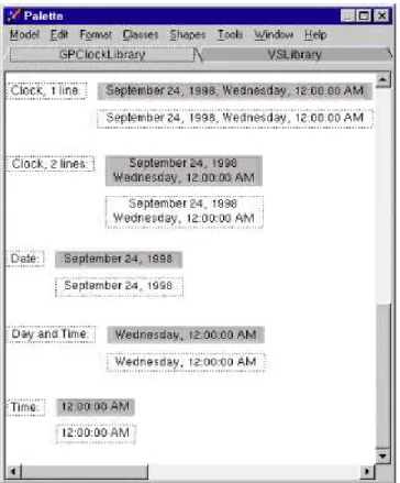
Figure 1. Reusable model components for time and date
The library provides a class, a set of methods that allow the manipulation of dates in the Gregorian calendar, and a mechanism to use the simulation clock as date and time. The reusable components allow the display of the simulation clock in the calendar in different forms as shown in Figure 1. Many options are available. The modeler can display only the time as well as the whole information of the calendar. The format of the date and the time can be modified.
A modeler who wishes to use the components in the library makes his or her new model depend on the library model. The palette window of the new model shows the reus-able components of the clock library as shown in Figure 1. Then the modeler clicks on a reusable component, drags and drops it in the new model to reuse it. The behavior and char-acteristics of each component are provided in the class.
The modeler can change the functionality of a particular reusable component. In the clock library’s class hierarchy, a class can be subclassed and new methods can be created. Creating a method with the same name of an existing method overrides it.
In using the library, the modeler should specify the date and time corresponding to simulated time zero in the Input Data window. If the simulation model is a terminating model then the date and time of the simulation termination must
also be specified in the Input Data window.
The modeler also specifies a time increment ∆t at the end of which the clock display is updated. Selection of the ∆t value affects the execution speed and should be determined accordingly.
2.2 The Distribution Library
This library has been developed for the purpose of facilitating the development of simulation models of parts distribution systems. A parts distribution visual simulation model can easily be developed in VSE with no programming by way of reusing model components from this library.
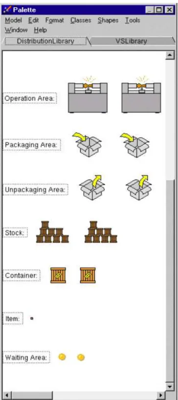
The library provides the following reusable model com-ponents: container, stock, packaging area, unpackaging area, waiting area, and operation area as shown in Figure 2. Each component is described below.
2.2.1 Container
A container is a dynamic object that physically moves from one point to another during simulation and contains items belonging to a specific class DTItem. A container can contain only one kind of item, identified by the attribute contentType. The type of an item is known through its method itemType. Figure 2 shows two container components: shallow (non-decomposed) or deep (decomposed). If it is deep, a container can contain instances of the class DTItem, whereas if it is shallow, it cannot. In the second case, the items are only represented by a number, the quantity of items the container contains.
2.2.2 Stock
A stock is a static component. Like a container, it can contain items belonging to the class DTItem. Unlike a container, a stock can contain several kinds of item. Information about items is classified according to the item type. For instance, the number of items in the stock is directly known by the item type. Global information is also available such as the total number of items in the stock.
The stock has a particular behavior. A message can be sent to the stock asking the release of a particular item. If the requested item does not exist in the stock, optionally the stock can first create the item and then release it. Data is col-lected on all new creations of stock. Usually, this informa-tion is outputted at the end of the simulainforma-tion as the number of items of a given type needed in the inventory in order to meet the customer demand.
Like containers, a stock can also be shallow or deep. In the case of a shallow component, only numbers represent the items in the stock.
Figure 2. Reusable model components for parts distribution
2.2.3 Packaging Area
A packaging area is a static component. A container
type of item the container can carry. This area can manage real items, i.e. deal with deep containers and deep stocks, as well as virtual items, i.e., deal with shallow containers and shallow stocks. Of course, the combination deep stock and shallow container, or vice versa, is incoherent. Finally, like many components of this library, the area can be deep or shallow.
2.2.4 Unpackaging Area
An unpackaging area is a static component. A container arriving on it is automatically emptied. The container’s items are moved to an associated shape that can be a stock. Like the packaging area, this area can manage real items as well as virtual items and the combination deep stock and shallow container, or vice versa, is also incoherent. Finally, like all the components of this library, the area can be deep or shal-low.
2.2.5 Waiting Area
In packaging and unpackaging areas, there can be only one dynamic object present at the same time. So, to control the access to such areas, there is the waiting area, which represents an area where dynamic objects wait before moving to an area accessible for only one object. Like all of the components of this library, the area can be deep or shallow. 2.2.6 Operation Area
This component represents just an area where a dynamic object can spend a given amount of time. The aim of such a component is to represent the dynamic object undergoing an operation for a given time. This component can be deep or shallow.
3. THE PARTS DISTRIBUTION MODEL
We have developed a VSE model of a parts distribution system of a local company in Blacksburg, Virginia, by way of reusing from the clock and distribution libraries. The com-pany manufactures parts that are stored on pallets. The pal-lets are loaded into trucks for transporting to customer plants in the US and Mexico. The objective of the simulation study was to estimate the number of pallets needed to distribute all manufactured parts to all customer sites.
The top-level component of the VSE model is the US map. The map component contains deep components repre-senting the customer plants, the manufacturing company, and the parts washing facility. A clock component is reused on the layout of the top-level component from the clock library. The top-level component class has a method to read Microsoft Excel files containing data about the orders of the customers and the weekly schedule of the pick-ups. At the beginning of simulation, the order and schedule data are read in and all associated dynamic objects are instantiated. Trucks
When a truck arrives, it is moved to a waiting area for the dock stations. A waiting area exists for each dock station associated with each kind of shipment. If a truck is empty, the kind of shipment it will contain is determined according to its destination. But if the truck contains pallets, the kind of shipment is defined by the type of the pallets.
The movement of the trucks between the plants is based on a weekly schedule showing the pick-up day and time of the week and a destination location. Trucks arrive in cus-tomer plants to deliver the parts and pick up dirty pallets and bring them to the washing facility. After they are washed, they are delivered to the manufacturing company.
When a customer orders parts, parts are produced according to the expected delivery time. The order triggers the preparation of pallets to transport the parts. The pallets are brought from the inventory and the manufactured parts are loaded on the pallets depending on the part type that requires a specific pallet. Then, the pallets are moved to the stock of prepared pallets which are picked up by a truck for transportation to a customer plant.
If the desired pallet is not in the inventory, a new one is created in the simulation and the statistics is updated. Note that the objective is to estimate the number of pallets needed for a distribution.
The pallets are delivered to the customer plant and put into “operation”. This “operation” corresponds to the situa-tion whereby the customer unloads the parts and uses them in the assembly line. We assume that at the end of the “oper-ation” the dirty pallets are available for pick-up by a truck delivering parts to the customer plant. The dirty pallets are loaded into the truck and transported to the parts washing facility nearby the parts manufacturing company.
When dirty pallets arrive in the washing facility, they are moved to the washing line. The start of the washing of a pal-let is symbolized by its arrival in the StartWashingArea com-ponent, belonging to the class StartOperationArea. The pallet is moved to the EndWashingArea component, taking some time corresponding to the time the pallet spends in the washing facility.
4. CONCLUDING REMARKS
Component-based model development enables a modeler to build a model by way of reuse with no programming. Com-ponent-based technology can only be achieved by using the object-oriented paradigm. The Visual Simulation Environ-mentTM software product enables component-based visual simulation model development with its fully and truly object-oriented capability inherent to its conceptual frame-work.
REFERENCES
Balci, O.; A.I. Bertelrud; C.M. Esterbrook; and R.E. Nance. 1998. “Visual Simulation Environment”. In Proceedings of the 1998 Winter Simulation Conference, SCS, San Diego, CA, 279-287.
Brown, A.W., Ed. 1996. Component-Based Software Engi-neering. IEEE Computer Society Press, New York, NY. Orca Computer, Inc. 1999a. Visual Simulation Environment
User’s Guide, Orca Computer Inc., Blacksburg, VA (http://www.OrcaComputer.com).
Orca Computer, Inc. 1999b. Visual Simulation Environment Reference Manual, Orca Computer Inc., Blacksburg, VA (http://www.OrcaComputer.com).
AUTHOR BIOGRAPHIES
BRUNO BACHELET performed the work described herein
when he was a graduate student in the Department of Computer Science at Virginia Tech. He is currently a Ph.D. student at ISIMA, Aubiere Cedex, France.
OSMAN BALCI is Professor of Computer Science at
Virginia Tech. He received B.S. and M.S. degrees from Bogazici University in 1975 and 1977, and M.S. and Ph.D. degrees from Syracuse University in 1978 and 1981. Dr. Balci is the Editor-in-Chief of two international journals: Annals of Software Engineering and World Wide Web; Verification, Validation and Accreditation (VV&A) Area Editor of ACM Transactions on Modeling and Computer Simulation; Simulation and Modeling Category Editor of ACM Computing Reviews; and serves on five other editorial boards. Dr. Balci is a Director at Large for the Society for Computer Simulation International (SCS) and is a member of the Winter Simulation Conference Board of Directors representing SCS. His current research interests center on software engineering, visual simulation and modeling, and world wide web. Dr. Balci is a member of Alpha Pi Mu, Sigma Xi, Upsilon Pi Epsilon, ACM, IEEE CS, INFORMS, and SCS.