HAL Id: hal-01977267
https://hal-enac.archives-ouvertes.fr/hal-01977267
Submitted on 10 Jan 2019
HAL is a multi-disciplinary open access
archive for the deposit and dissemination of
sci-entific research documents, whether they are
pub-lished or not. The documents may come from
teaching and research institutions in France or
abroad, or from public or private research centers.
L’archive ouverte pluridisciplinaire HAL, est
destinée au dépôt et à la diffusion de documents
scientifiques de niveau recherche, publiés ou non,
émanant des établissements d’enseignement et de
recherche français ou étrangers, des laboratoires
publics ou privés.
3D direction-of-arrival estimation using a wideband
vector antenna
Johan Duplouy, Christophe Morlaas, Hervé Aubert, Patrick Potier, Philippe
Pouliguen, Christopher Djoma
To cite this version:
Johan Duplouy, Christophe Morlaas, Hervé Aubert, Patrick Potier, Philippe Pouliguen, et al.. 3D
direction-of-arrival estimation using a wideband vector antenna. IEEE International Symposium on
Antennas and Propagation and USNC-URSI Radio Science Meeting (APS/URSI 2018), Jul 2018,
Boston, MA, United States. pp.197-200, �10.1109/lawp.2017.2779878�. �hal-01977267�
3D Direction-of-Arrival Estimation using a
Wideband Vector Antenna
J. Duplouy
∗†‡, C. Morlaas
∗‡, H. Aubert
†‡, P. Potier
§, P. Pouliguen
§and C. Djoma
§∗TELECOM-EMA, ENAC, F-31055 Toulouse, France, Email: [email protected] †LAAS-CNRS, MINC, F-31400 Toulouse, France
‡ Toulouse University, F-31400 Toulouse, France §DGA, F-75509 Paris, France
Abstract—In this communication, direction finding perfor-mances of a reconfigurable wideband vector antenna are pre-dicted. The accurate estimation of the direction of arrivals across the 3D half-space of incoming electromagnetic fields is obtained over a 1.7:1 frequency range from only two colocated and orthogonal circular arrays of Vivaldi antennas.
I. INTRODUCTION
The direction-of-arrival (DoA) estimation of incoming elec-tromagnetic (EM) fields has gained a significant position in numerous civil and defense related applications [1]. Some applications may require a 3D coverage and wide operating frequency range. Keeping in mind that the estimation accuracy of the DoAs along with the spatial and frequency coverages mainly depends on the electrical performances of the antennas, it becomes important to focus on the development of specific direction finding (DF) antennas with 3D and wideband cover-ages capabilities. A way to estimate the DoA of an incoming EM field in the 3D space with a compact DF antenna consists of using a Vector Antenna (VA) [2]. Ideal VA is composed of six orthogonal and colocated antennas and combines three electric and three magnetic dipoles. These six dipoles allow the derivation of the DoA from the measurement of the six components of the incoming EM field. Several VA designs covering the 3D space have been reported. An active VA operating at frequencies below 30 MHz is studied in [3], while some of us proposed in [4] a passive VA for multi-band applications.
The DoA estimation performances of the passive, wideband and reconfigurable VA reported by the authors in [5] are assessed in this communication.
II. RECONFIGURABLEWIDEBANDVECTORANTENNA
The novel passive, wideband and reconfigurable VA, which was recently proposed by the authors [5], is shown in Fig. 1. It consists of two orthogonal and colocated dual-port semi-circular arrays of Vivaldi antennas. As specified in Table I, three components of the incoming EM field (Hx, Hy and Ez)
can be measured over a 1.7:1 simulated impedance bandwidth (VSWR 6 2.3) ranging from 2.08 GHz to 3.56 GHz thanks to the control of the amplitude and phase impressed at the four ports of the VA. The VA is included in a half-sphere of radius 0.52λ0, where λ0 is the free space wavelength at the lowest
operating frequency.
Port 4 Port 2
Port 1 Port 3
Fig. 1. Topology of the VA reported in [5] and ports numbering description
TABLE I
EXCITATION CONFIGURATIONS FOR THE MEASUREMENT OF THE INCOMINGEM-FIELD COMPONENTS
Measured
Port 1 Port 2 Port 3 Port 4 Component
Hx 1 1∠180◦ 0 0
Hy 0 0 1 1∠180◦
Ez 1 1 1 1
III. DIRECTIONFINDINGPERFORMANCES
Two simulated configurations are considered here to eval-uate the DoA estimation performances of the reconfigurable wideband VA: (1) the antenna is mounted on an infinite ground plane, and (2) the antenna is mounted on a finite metallic and octagonal support with a circumcircle radius of 1.13λ0.
DoAs are estimated in the 3D half-space using the well-known MUSIC algorithm (MUltiple SIgnal Classification) [6] and from full-wave EM simulations (HFSS software). Each DoA is defined by the azimuth angle φ ∈ [0; 360◦] and elevation
angle θ ∈ [0; 90◦]. The accuracy of the DoA estimation
is derived from the computation of the Root-Mean-Square error of the angular distance, denoted by ∆aRMS, between
the estimated DoA and the actual DoA (see, e.g., [4] for the detailed definition of ∆aRMS). Furthermore, the evaluation
of the estimation performances is based on the following assumption: only one vertically polarized EM-wave is incident upon the VA. Other estimation parameters used for performing the simulations are summarized in Table II. Following [4], a calibration matrix derived from simulated radiation patterns
of two magnetic and one electric dipoles is used to take into account eventual amplitude and phase distortions in the radiation patterns.
TABLE II
PARAMETERS USED FOR THE EVALUATION OF THE DIRECTION FINDING PERFORMANCES
DoA Algorithm MUSIC
Number of incoming EM fields 1 Polarization of the incoming EM fields Vertical
Angular coverage φ ∈ [0◦;90◦] θ ∈ [0◦;90◦]
Angular resolution ∆φ = 5◦ ∆θ = 2◦
Incoming EM fields power density -105 dBW.m-2
Noise power level -111 dBm Incoming signal power density to noise ratio 36 dB.m-2
Snapshots per DoA estimation 100 Number of estimations per DoA 20 Frequencies used the DoA finding
2.2 GHz 2.8 GHz 3.4 GHz
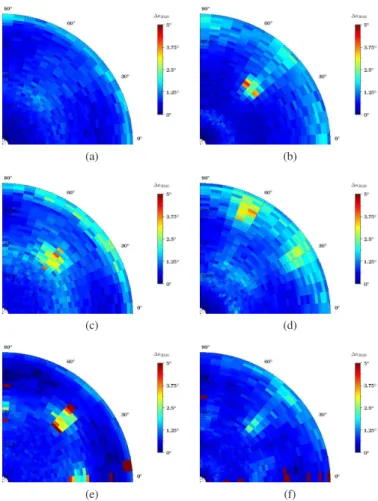
Fig. 2 reports the simulated Root-Mean-Square of angular distance∆aRMSat three operating frequencies in the bandwidth
of the VA. For both configurations, it can be observed that the ∆aRMS does not exceed 5 degrees in almost every directions
in the 3D upper half-space within the antenna bandwidth. Furthermore, highest values of ∆aRMS are found in specific
directions depending on the operating frequency and the configuration (infinite or finite ground plane). However, it can be observed that the use of the finite ground plane does not significantly degrade the estimation performances. From the simulation results reported in Table III, where the 95th and 99th percentiles of the ∆aRMS (which indicate the errors
threshold for respectively 95% and 99% of all the obtained DoAs) are given, it can be predicted that the VA is suitable for 3D direction finding estimation with a very good estimation accuracy.
TABLE III
DFPERFORMANCES PREDICTED FROM FULL-WAVE ELECTROMAGNETIC SIMULATIONS
Infinite ground plane
Frequency max∆aRMS 99th ∆aRMS 95th ∆aRMS
2.2 GHz 2.8◦ 2.3◦ 1.5◦
2.8 GHz 4.0◦ 3.1◦ 2.3◦
3.4 GHz 85.2◦ 12.0◦ 2.1◦
Finite ground plane
Frequency max∆aRMS 99th ∆aRMS 95th ∆aRMS
2.2 GHz 4.2◦ 2.4◦ 1.7◦
2.8 GHz 3.8◦ 2.8◦ 2.0◦
3.4 GHz 142.5◦ 51.8◦ 1.6◦
CONCLUSION
The DF performances of a reconfigurable wideband VA which emulates two magnetic and one electric dipoles is pre-sented, showing a design with a high level of DoA estimation accuracy over a 1.7:1 frequency range with a 3D field of view. Experimental validations of these predicted performances are on tracks.
(a) (b)
(c) (d)
(e) (f)
Fig. 2. Simulated∆aRMS(φ, θ) at: (a) & (b) 2.2 GHz, (c) & (d) 2.8 GHz,
and (e) & (f) 3.4 GHz when the reconfigurable wideband VA is mounted on an infinite ground plane (left figures) or on a finite octagonal ground plane (right figures). Elevation angles θ are given on the radial axis and azimuth angles φ are given on the angular axis.
ACKNOWLEDGEMENT
The authors would like to thank the French Defense Agency (Direction G´en´eral de l’Armement, DGA) and the Occitanie regional council for their financial support.
REFERENCES
[1] T. E. Tuncer and B. Friedlander, Classical and Modern Direction-of-Arrival Estimation. Academic Press, 2009.
[2] A. Nehorai and E. Paldi, “Vector-sensor array processing for electro-magnetic source localization,” IEEE Transactions on Signal Processing, vol. 42, no. 2, pp. 376–398, Feb. 1994.
[3] B. Almog, “Compact 3D direction finder,” Patent, Mar. 20, 2013, EP20120184835.
[4] J. Lomin´e, C. Morlaas, C. Imbert, and H. Aubert, “Dual-band vector sensor for direction of arrival estimation of incoming electromagnetic waves,” IEEE Transactions on Antennas and Propagation, vol. 63, no. 8, pp. 3662–3671, Aug. 2015.
[5] J. Duplouy, C. Morlaas, H. Aubert, P. Pouliguen, P. Potier, and C. Djoma, “Reconfigurable grounded vector antenna for 3D electromagnetic di-rection finding applications,” IEEE Antennas and Wireless Propagation Letters, accepted in 2017, in press, doi: 10.1109/LAWP.2017.2779878. [6] R. Schmidt, “Multiple emitter location and signal parameter estimation,”
IEEE Transactions on Antennas and Propagation, vol. 34, no. 3, pp. 276–280, Mar. 1986.
![Fig. 1. Topology of the VA reported in [5] and ports numbering description](https://thumb-eu.123doks.com/thumbv2/123doknet/14250263.488101/2.918.482.828.308.490/fig-topology-va-reported-ports-numbering-description.webp)