HAL Id: tel-01175971
https://tel.archives-ouvertes.fr/tel-01175971
Submitted on 13 Jul 2015HAL is a multi-disciplinary open access archive for the deposit and dissemination of sci-entific research documents, whether they are pub-lished or not. The documents may come from
L’archive ouverte pluridisciplinaire HAL, est destinée au dépôt et à la diffusion de documents scientifiques de niveau recherche, publiés ou non, émanant des établissements d’enseignement et de
First Instants of Gas Phase Ethylene Polymerisation
Barbara Hazard Browning
To cite this version:
Barbara Hazard Browning. Dynamic Modelling of a Fixed Bed Reactor to Study the First Instants of Gas Phase Ethylene Polymerisation. Chemical and Process Engineering. Université Claude Bernard - Lyon I, 2013. English. �NNT : 2013LYO10109�. �tel-01175971�
N° d’ordre 109-2013 Année 2013 THESE DE L‘UNIVERSITE DE LYON
Délivrée par
L’UNIVERSITE CLAUDE BERNARD LYON 1 Ecole Doctorale de Chimie
DIPLOME DE DOCTORAT Spécialité GENIE DES PROCEDES
(arrêté du 7 août 2006)
soutenue publiquement le 09 Juillet 2013 par
Mme. HAZARD BROWNING Barbara
Directeur de thèse: M. McKENNA Timothy JURY: Mme. TAYAKOUT Melaz (President)
M. LATIFI Abderrazak (rapporteur) M. EDOUARD David (rapporteur) M. JOLY Jean-François
M. McKENNA Timothy Mme. PITAULT Isabelle
Dynamic Modelling of a Fixed Bed Reactor to Study the First Instants of
Gas Phase Ethylene Polymerisation
Président de l’Université
Vice-président du Conseil d’Administration
Vice-président du Conseil des Etudes et de la Vie Universitaire Vice-président du Conseil Scientifique
Directeur Général des Services
M. François-Noël GILLY
M. le Professeur Hamda BEN HADID M. le Professeur Philippe LALLE M. le Professeur Germain GILLET M. Alain HELLEU
COMPOSANTES SANTE
Faculté de Médecine Lyon Est – Claude Bernard
Faculté de Médecine et de Maïeutique Lyon Sud – Charles Mérieux
Faculté d’Odontologie
Institut des Sciences Pharmaceutiques et Biologiques Institut des Sciences et Techniques de la Réadaptation
Département de formation et Centre de Recherche en Biologie Humaine
Directeur : M. le Professeur J. ETIENNE Directeur : Mme la Professeure C. BURILLON Directeur : M. le Professeur D. BOURGEOIS Directeur : Mme la Professeure C. VINCIGUERRA Directeur : M. le Professeur Y. MATILLON Directeur : M. le Professeur P. FARGE
COMPOSANTES ET DEPARTEMENTS DE SCIENCES ET TECHNOLOGIE
Faculté des Sciences et Technologies Département Biologie
Département Chimie Biochimie Département GEP
Département Informatique Département Mathématiques Département Mécanique Département Physique
Département Sciences de la Terre
UFR Sciences et Techniques des Activités Physiques et Sportives Observatoire des Sciences de l’Univers de Lyon
Polytech Lyon
Ecole Supérieure de Chimie Physique Electronique Institut Universitaire de Technologie de Lyon 1
Directeur : M. le Professeur F. DE MARCHI Directeur : M. le Professeur F. FLEURY Directeur : Mme le Professeur H. PARROT Directeur : M. N. SIAUVE
Directeur : M. le Professeur S. AKKOUCHE Directeur : M. le Professeur A. GOLDMAN Directeur : M. le Professeur H. BEN HADID Directeur : Mme S. FLECK
Directeur : Mme la Professeure I. DANIEL Directeur : M. C. COLLIGNON
Directeur : M. B. GUIDERDONI Directeur : M. P. FOURNIER Directeur : M. G. PIGNAULT Directeur : M. C. VITON
A joke in a verse
“A rose coloured swan,” I heard him say, I raised my eyes and looked away,
"But there it is for you to see Look, floating past that willow tree!" "That swan is white my friend," I said, He looked at me and shook his head,
"Maybe what you say is true, But roses are white, I've seen them too!"
Reginald Henry Barnes (1920 – 2006)
The purpose of science is not to analyze or describe, but to make useful models of the world. Edward de Bono (1933 - ) Nature is written in mathematical language. Galileo Galilei (1564 – 1642)
This thesis was prepared at
Laboratoire de Génie des Procédés Catalytiques Université de Lyon, CNRS-CPE Lyon in collaboration with
Laboratoire Chimie, Catalyse, Polymères et Procédés, Université de Lyon, CNRS-CPE Lyon-UCBL Laboratoire d'Automatique et de Génie de Procédés, Université de Lyon, CNRS-UCBL, CPE Lyon
There are certain people without whom this thesis would never have been written. In particular, it has been my privilege to work with my thesis directors, Isabelle Pitault and Timothy McKenna, who have given me unwavering support and invested both their time and energy in this project. Thank you Isabelle, for having confidence in me and offering me the chance to model this reactor, and also for your expertise, clear thinking and ability to always see the whole picture. Thank you Tim, for having offered to extend the modelling project into a thesis and for you own expertise, ideas, encouragement and for speaking to me in English! Many thanks must also go to Claude de Bellefon, LGPC laboratory director, for your support, for being so flexible about the working week and, especially, for arranging a ‘baptême de plongée’ for my daughter, Isabelle!
Particular thanks also to Nida Othman for your skill, help and tuition and to Estevan Tioni, without whom there would have been no experiments to model! Thanks to other members of C2P2 who have been involved in and supported my work. Vincent Monteil has brought his wide polymerization knowledge and background to discussions regarding the model and Jean-Pierre Broyer has given endless practical help with the experimental set-up.
Significant contributions to this project have also been made by Frederic Bornette, who has always been on hand to help in any way, and Fabrice Campoli, whose welding abilities are second to none, many thanks to both of you. Thanks also to all the other members of LGPC, who have helped me in various ways, work related and not. Stephanie, Jean-Noel, Fred, Ahmed gave my son, Thomas, a cool work experience week. Laurent, thank you for letting me share your office …and for the good hiking ideas …and for tutoring my daughter in maths …and for making the office such a pleasant place to be!
Last but not least, thanks must go to all those people outside the workplace who have given me encouragement and support. Thanks to my Dad, who used to ‘make molecules’ and walk us up and down mountains at every opportunity and to my brilliant, caring and funny sister. Thanks to my all friends and to my children, Thomas, Isabelle, Marianne and Emily for being yourselves and to my husband, Peter, thanks for supporting me throughout this thesis and in life!
La polymérisation des oléfines à l’aide de catalyseurs metallocène est une réaction développée au niveau industriel. Bien que les premiers instants de la réaction aient une importance déterminante pour le procédé, ils n’ont fait l’objet que de très peu de travaux de recherche. Dernièrement, le l’équipe du prof. Mc Kenna a conçu un réacteur de type lit fixe pour étudier en détail ces premiers instants de la réaction. Néanmoins, face à la complexité de la réaction étudiée, un travail de modélisation s’avérait nécessaire afin de mieux appréhender l’ensemble des phénomènes influant sur les résultats et ainsi proposer des améliorations à ce montage expérimental. C’est ce travail qui est présenté dans ce manuscrit.
Le premier modèle considère le réacteur comme un calorimètre semi-ouvert sur la matière en entrée, et utilise des lois cinétiques simplifiées. Il a ainsi était démontré que l’augmentation de la température dans le réacteur était un paramètre particulièrement important. Le design a ainsi été modifié en conséquence afin de contrôler l’exothermie de la réaction.
Dans un second temps, une étude fine sur les mesures de pression récupérées dans le réacteur a été réalisée mettant en avant que le régime transitoire de montée en pression avait un rôle clef sur cette réaction. L’intégration de ces données a permis d’améliorer le modèle utilisé. Contrairement aux résultats obtenus sur des temps de réaction longs, il a été démontré que la désactivation était plus rapide à basse température lors des premiers instants de la réaction.
Mots Clés: modélisation de réacteur; polymérisation d’oléfines; transfert de chaleur; début de polymérisation
The behaviour of silica supported metallocene catalyst in the early moments of olefin polymerization is not well understood. The complexity, rapidity and high exothermicity of the reaction impede observation of the kinetics and morphological changes. The fixed bed reactor constructed by McKenna’s group is designed to study these first instants of gas phase olefin polymerisation. The purpose of the modelling work presented is to gain understanding and improve the set-up through better knowledge of the reactor conditions. After a literature survey, the existing set-up was reviewed and analysed. A reactor model was constructed and programmed with polymerisation kinetics represented by a simple relation. The model was validated for individual experiments under optimised conditions. Use of the reactor as a calorimeter was evaluated and a state observer for the polymerisation rate was tested. The model was also used to show that very high temperatures are possible in the reactor bed and to simulate effects of changes to reactor construction and operating conditions.
The reactor pressurisation profile is non negligible for experiments of shorter duration. New kinetics based on this were incorporated into the model: these were able to represent series of experiments and take account of the deactivation reaction. Contrary to results from longer duration experiments, our model finds initial deactivation does not appear to be controlled by temperature.
Introduction ... 1
1 Literature Review ... 7
1.1 Introduction ... 7
1.1.1 Polyethylene and Polypropylene ... 7
1.1.1.1 Low Density Polyethylene ... 8
1.1.1.2 Polyethylene from Co-ordination Catalysis ... 8
1.1.2 Catalyst Types ... 9
1.1.2.1 Chromium Oxide Catalyst ... 9
1.1.2.2 Ziegler-Natta Catalyst ...10
1.1.2.3 Metallocenes ...10
1.1.3 Catalyst Supports ...11
1.1.3.1 Magnesium Chloride (MgCl2) ...12
1.1.3.2 Amorphous Silica ...12
1.1.3.3 Supporting Metallocene Catalyst and MAO on Silica ...13
1.1.4 Industrial Scale Reactors ...14
1.2 Polymerisation and Experimental Investigations ...19
1.2.1 The Study of Fragmentation and the Origin of Particle Morphology ...19
1.2.2 Reactors for Laboratory Scale Investigation...20
1.2.2.1 Conventional Stirred Bed Reactors ...21
1.2.2.2 Fluidised Bed Systems ...21
1.2.2.3 On-line Microreactors Coupled With Microscopy ...22
1.2.2.4 Stopped Flow Reactors ...23
1.2.2.4.1 Homogeneous Olefin Polymerisation ...24
1.2.2.4.2 Slurry Phase ZN/MgCl2 Catalyst Systems ...24
1.2.2.4.3 Gas Phase Systems ...26
1.2.3 Off-line studies of the initial moments of polymerisation ...28
1.2.3.1 Microscopy and Tomography ...29
1.2.3.2 Measurement of Specific Surface ...33
1.2.3.3 Effect of Changing Support Properties ...33
1.2.3.3.1 Pore Volume ...33
1.2.3.3.2 Friability ...33
1.2.3.3.3 Pore Size Distribution ...34
1.2.3.3.4 Primary Particle Size and Specific Surface ...35
1.2.3.3.5 Particle Size ...35
1.3 Modelling ...37
1.3.1 Reaction Kinetics ...37
1.3.1.2 Simplified Models ...37
1.3.1.2.1 Activation Step ...38
1.3.1.2.2 Propagation ...39
1.3.1.2.3 Deactivation ...41
1.3.1.3 Conclusion ...42
1.3.2 Particle Scale Modelling...43
1.3.2.1 The Micrograin and Particle Flow Models ...44
1.3.2.2 Morphology Models ...46
1.3.3 Reactor Scale Modelling and Monitoring ...48
1.3.3.1 Polymerisation Reactors ...48
1.3.3.2 Fixed Bed Reactor Modelling and Design ...48
1.3.3.2.1 Model Type...49
1.3.3.2.2 Heat Transfer Correlations for Packed Beds ...51
1.3.3.2.3 Packed Bed Dilution ...52
1.3.3.2.4 Design of Fixed Bed Reactors ...52
1.4 Conclusion ...55
1.5 Nomenclature ...58
2 Reactor Model Development ...71
2.1 Reactor and System ...71
2.1.1 Purpose ...71
2.1.1.1 Experimental Set-up ...71
2.1.1.2 Reactor Model ...71
2.1.2 Description ...72
2.1.2.1 Reactor and Set-up...72
2.1.2.2 Materials ...73
2.1.2.3 Operating Method ...74
2.1.2.4 Experimental Results ...74
2.1.3 Review of the Experimental System and Operating Methods ...75
2.1.3.1 Stainless Steel Frits ...77
2.1.3.2 System Pressure Drops ...77
2.1.3.2.1 Reactor Bed ...77
2.1.3.2.2 Heating Coils ...78
2.1.3.2.3 Stainless Steel Frits ...78
2.1.3.2.4 CO2 Pressure and Flowrate ...79
2.1.3.3.2 Compression Effects ...80
2.1.3.3.3 Position of the Inlet Thermocouple ...82
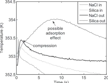
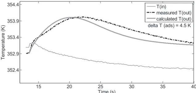
2.1.3.3.4 Adsorption of Ethylene on Silica ...82
2.1.3.3.5 Gas Expansion ...84
2.1.3.3.6 Conclusion ...85
2.1.3.4 Reaction Rate Profile ...85
2.1.3.5 Packed Bed Dilution ...86
2.1.3.5.1 NaCl Particle Size...86
2.1.3.5.2 Bed Uniformity and Stability ...87
2.1.3.5.3 Effect on Reaction Kinetics ...88
2.1.4 Conclusion ...88
2.2 Model Construction ...89
2.2.1 Heat Transfer Correlations ...89
2.2.1.1 Particle Heat Transfer Coefficient ...89
2.2.1.2 Effective Conductivity and Internal Wall Heat Transfer Coefficient ...90
2.2.2 Model Type ...91
2.2.2.1 Radial Heat Transfer ...91
2.2.2.2 Inter-particle Heat and Mass Transfer ...91
2.2.2.3 Intraparticle Mass Transfer ...93
2.2.2.4 Conclusion ...94
2.2.3 Adsorption ...95
2.2.4 Mass and Heat Balances ...96
2.2.4.1 Reaction Period ...96 2.2.4.1.1 Material Balances ...96 2.2.4.1.2 Energy Balances ...98 2.2.4.2 Cooling Period ... 101 2.2.5 Reaction Rate ... 101 2.2.5.1 Kinetic Model ... 101 2.2.5.2 Ethylene Solubility in PE ... 103 2.2.6 Conclusions ... 105
2.3 Programming the model ... 107
2.3.1 Structure ... 107
2.3.2 Resolution of Differential Equations ... 107
2.3.3 Number of Elements ... 108
2.4 Conclusion ... 109
2.5 Nomenclature ... 110
3.1 Validation ... 119
3.1.1 Experiments without Catalyst ... 119
3.1.2 Experiments with Catalyst ... 120
3.1.3 Position of Inlet Thermocouple... 123
3.1.4 Position of Exit Thermocouple ... 124
3.1.5 Internal Thermocouple ... 126
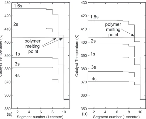
3.1.5.1 Polymer Melting Point ... 127
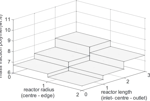
3.1.6 Polymer Distribution ... 129
3.1.7 CO2 Flowrate ... 132
3.1.8 Numerical Dispersion ... 133
3.1.9 Conclusion ... 133
3.2 Calorimetry ... 135
3.2.1 The Fixed Bed Reactor as a Calorimeter ... 136
3.2.2 Construction of the High Gain Observer ... 136
3.2.2.1 Model Simplifications ... 136
3.2.2.2 State-Space Form of Model ... 138
3.2.2.3 Observability ... 140
3.2.2.4 Change of Variables ... 140
3.2.2.5 Correction Term ... 141
3.2.2.6 Observer Programming ... 142
3.2.2.7 Data from Model ... 143
3.2.2.8 Results for Single Element Observer ... 144
3.2.2.9 Results for Multiple Element Observer ... 146
3.2.3 Observer for kCC2C* ... 148
3.2.4 Conclusion ... 153
3.3 Simulations ... 155
3.3.1 Reduced Flowrate Experiments ... 155
3.3.2 Alternative Reactor Geometries ... 157
3.3.3 Increasing Flowrate ... 158
3.3.4 Exit Frit ... 160
3.3.4.1 Existing Frit ... 160
3.3.4.2 Reduced Mass Exit Frit ... 161
3.3.4.3 Alternative Frit Materials ... 163
3.3.4.4 Conclusion ... 165
3.3.7 Conclusion ... 171
3.4 General Conclusions ... 173
3.5 Nomenclature ... 175
4 Reactor Model: Further Developments ... 181
4.1 Experiments with Internal Thermocouple ... 181
4.1.1 Reactor Configuration ... 181
4.1.2 Reactor Testing ... 182
4.1.3 Reduced Catalyst Activity ... 184
4.2 Reactor Pressurisation ... 187
4.2.1 Measurement of the Pressurisation Rate ... 187
4.2.1.1 First Order System... 187
4.2.1.2 Comparison with Heat of Compression ... 188
4.2.1.3 Increased Capacity Pressure Controller ... 188
4.2.1.4 Reactor Exit Flowrate ... 189
4.2.2 Model with Pressurisation ... 190
4.2.2.1 Typical Results ... 190
4.2.2.2 Observer ... 191
4.2.2.3 100ms Experiment ... 192
4.2.2.4 Increased Pressurisation Rate ... 193
4.2.3 Activity Profiles ... 194
4.2.3.1 Lower Flowrate ... 195
4.2.3.2 Higher Flowrate ... 197
4.2.3.3 New Reaction Kinetics ... 199
4.2.4 Conclusion ... 203
4.3 Reaction Kinetic Model with Deactivation... 205
4.3.1 Material Balances ... 205 4.3.2 Modelling Results ... 207 4.3.2.1 Higher Flowrate ... 207 4.3.2.2 Lower Flowrate ... 209 4.3.3 Conclusion ... 210 4.4 General Conclusions ... 211 4.5 Nomenclature ... 212
5 Conclusions and Perspectives ... 215
Appendix 1 – List of Experiments ... 219
Appendix 2 - Physical Data and Reactor System Measurements ... 223
Introduction
The gas phase polymerisation of ethylene is of great economic importance, with several tens of millions of tonnes produced annually. This is a heterogeneously catalysed process, with different types of active sites dispersed on a highly porous solid support; Ziegler-Natta catalysts, TiCl4 dispersed on MgCl2, and chromium catalysts, CrOx dispersed on silica are the
two most common examples. The reaction is rapid and highly exothermic and the polymer accumulates as a solid at the active sites on the catalyst support. This leads to particle growth and also to rapid changes in the physical structure of the catalyst support and the environment of the active sites. The catalyst and polymerisation behaviour during the first instants is critical to the success of the polymerisation and quality of the final product. It could be said to lay the foundations for the whole polymerisation.
The first moments of the polymerisation are particularly complex because catalyst particles must undergo a transition period where the physical properties of the polymer and catalyst support are changing rapidly. The catalyst support must break up in a controlled way to allow the developing polymer particle to grow. The reaction is also at its most intense, just when the particle surface area for heat transfer is at a minimum, so overheating is a risk. The polymerisation is typically carried out at 353K. The melting point of polyethylene (PE) is about 400K and forms an upper limit for the permissible reaction temperature. Above this, the polymer softens and melts, becoming sticky and blocking catalyst pores.
For industrial gas phase polyethylene processes, the first moments of the reaction are particularly problematic because introducing fresh catalyst particles to monomer under normal reaction conditions can result in overheating. This can lead to reactor fouling or catalyst disintegration, producing fines. The step is usually carried out as a separate pre-polymerisation stage before the catalyst particles are fed to the main reactor. Improved understanding of the effects of the initial contact between the catalyst and monomer could lead to more resilient catalysts or better control methods and is therefore of great industrial interest.
From a research point of view, the interest is to gain understanding of this initial period which is so complex and difficult to observe. The main factors to be overcome in studying heterogeneous gas phase olefin polymerisation are the rapidity and exothermicity of the reaction and the short duration of the critical period. Also, in industry the gas phase process
must be handled under an inert atmosphere. Finally, this is a period of flux for the physical properties of the polymer and growing catalyst particle, which adds complexity to the meaning of measured data. A reactor to study the first instants of gas phase olefin polymerisation must therefore meet challenging criteria.
McKenna’s group [1,2] developed a fixed bed reactor for this purpose. The reactor is designed to operate close to industrial conditions and is constructed with a cartridge to contain the catalyst. This allows the fixed bed to be prepared and manipulated in the glove box. The mass of catalyst used is about 40 mg, diluted to 3-5wt% of the fixed bed by mixing with a chemically inert solid. Computer controlled solenoid valves with a minimum time of 100 milliseconds between subsequent actions were fitted to the gas supply and outlet to allow experiments of very short duration to be carried out. Temperature control was via a hot water bath. Temperature measurement at the reactor inlet and outlet was used to monitor the reaction. This fixed bed reactor is not isothermal and the polymerisation kinetics and catalyst behaviour are temperature dependent so a clear understanding of the reaction conditions is needed.
Experiments showed that, despite the hot water bath, overheating could occur in the fixed bed reactor. The measured reactor outlet temperatures were high and the polymer in the reactor showed visible signs of melting, forming a solid block of polymer in the hotter areas of the bed rather than free flowing grains. Tioni [3] made improvements to the reactor system and its operation to moderate the reaction temperature. The ethylene gas was diluted with helium in a molar ration of 2:1, alternative seedbeds were tested for dilution of the solid catalyst and the gas velocity through the fixed bed was maximised. However, a good estimate of temperature and concentration profiles within the reactor bed was still needed. The data available to calculate this was the reactor inlet and outlet temperatures measured externally to the bed supports, the masses of catalyst used and polymer formed and the reaction gas flowrate.
This thesis focuses on the dynamic modelling of a fixed bed reactor for the study of the first instants of gas phase ethylene polymerisation with silica supported metallocene catalyst based on the experiments carried out by Tioni [3]. Following a literature review on olefin polymerisation, polymerisation reactors used in industry and modelling of catalytic reactors, I will present my work to model this reactor using a simple relation to represent the reaction kinetics. Thermal phenomena aside from the main reaction are identified to occur in the fixed bed and significant axial temperature gradients were found. Modelling work using a state observer to estimate the reaction rate will then be presented and modifications to
improve the reactor and set-up will be proposed. Finally, I will present an improved kinetic model which provides a closer fit with the series of experimental data.
[1] Olalla B., Broyer J.P. & McKenna T.F.L., Heat Transfer and Nascent Polymerisation of Olefins on Supported Catalysts. Macromol. Symp. 271 (2008) 1-7
[2]Tioni E., Broyer J.P., Spitz R., Monteil V. & McKenna T.F.L., Heat Transfer in Gas Phase Olefin Polymerisation, Macromol. Symp. 285 (2009) 58-63
[3] Tioni E., Optimisation of a Tool to Study the Start-up of the Gas Phase Olefin Polymerisation, Ph.D. Thesis UCBL1 338-2011
Chapter 1
Literature Review
1 Literature
Review
1.1 Introduction
The main work presented in this thesis is the modelling of a laboratory scale reactor to study the kinetics of gas phase olefin polymerisation, and in this case, used for ethylene polymerisation. This chapter consists of a literature review divided into three sections. The first section introduces the subject with some background and history about PE and its importance. A brief review of the different chemical processes and catalysts used in PE manufacture is given along with a description of the main types of catalyst support used. This is followed by a description of the reactors used for ethylene polymerisation in industry. The focus is directed towards supported metallocene catalysts as this is the type used in the experiments modelled in this work.
The second part of the literature review covers the different types of reactors and experimental methods which have been used to investigate the first instants of olefin polymerisation using coordination catalysts. Both on-line methods, which follow the polymerisation in real time, and off-line studies, which give a snapshot view of the process, are considered.
Finally, the subject of the third section is modelling at each of the various scales of the polymerisation. Data found in the literature regarding the reaction kinetics of ethylene polymerisation with metallocene catalyst is reported. Particle scale and fixed bed reactor modelling are also reviewed.
1.1.1 Polyethylene and Polypropylene
PE molecules are chains formed with ethylene as monomer; the properties are dependent upon the chain length distribution, and the amount and type of branching which occurs during the polymerisation process. Less branching tends to increase polymer crystallinity and therefore density, resulting in a stronger but less flexible product [1]. PE is often classified by density with the following ranges and terminology:
x ULDPE/VLDPE, Ultra/Very low density polyethylene, <0.915 g.cm-3
x LDPE, Low density polyethylene, 0.915 - 0.94 g.cm-3
Whilst the chemistry of the catalysts used can differ, ethylene and propylene polymerisation share many similarities from the point of view of the fundamental issues surrounding heat and mass transfer, as well as particle growth in catalysed processes. In this thesis we are concerned with ethylene polymerisation. However, in general, conclusions drawn from either process can be applied to both PE and polypropylene (PP) systems.
1.1.1.1 Low Density Polyethylene
The first PE to be manufactured on a commercial basis was low density polyethylene (LDPE) introduced by Imperial Chemical Industries in 1938 [2]. LDPE is made by free radical polymerisation at very high pressures (up to 2750 bar [2]) and high temperatures (up to 350°C) in tubular or autoclave reactors. The product is a highly branched, partly crystalline material. The branching results from the free radical polymerisation mechanism that includes back-biting, which creates short chain branches, and transfer to polymer which causes long chain branches. This is the only means of making LDPE with long chain branches which confer rheological properties to the material useful for downstream processing. Some uses are packaging films, plastic bags and cable insulation [1].
Catalysed processes were originally intended as a means to circumvent the rather extreme reaction conditions used to make LDPE. However, 75 years after LDPE entered into production, a cost-effective means of making PE with long chain branches via a catalytic process remains elusive. LDPE thus remains a commercially important material despite the process-related challenges of operating at high pressures. Nevertheless, we will not treat this type of polymer in the current thesis, focusing instead on catalysed polymerisations.
1.1.1.2 Polyethylene from Co-ordination Catalysis
PE formed by catalysis is different from that produced by free radical polymerisation because the transfer reactions which cause long and short chain branches do not occur at the active site of the catalyst, and the polymer chains grow only by inserting one monomer unit after another. In these processes, different amounts of D-olefins are used to create short chain branches on the main PE chain, and thus control the density of the final product. High density polyethylene (HDPE) has few branches (i.e. only very low levels of D-olefin comonomers are used) resulting in a more crystalline, stronger, stiffer material than LDPE. When more short chain branches on the polymer chain are created by co-polymerisation, the resulting polymer is a linear low density polyethylene (LLDPE).
It is possible to change process conditions and concentrations midway through the polymerisation and create a final polymer which comprises chains with a wider range of
branching than could be produced under fixed conditions. This is important because in industry two reactors are often used in series as a means of changing the conditions mid-polymerisation to control polymer properties.
1.1.2 Catalyst Types
Table 1-1, taken from Polyolefin Reaction Engineering by Soares & McKenna [3], gives a summary of the main catalyst groups used in olefin polymerisation. Two types of polymer are distinguished: uniform and non-uniform. This is because supporting the catalyst can lead to different effects. Uniform polymer is produced when there is no interaction between the catalyst molecule and the support, so only one type of active site is present and polymer is formed with a narrow molecular weight distribution and a polydispersity index (PDI) of 2. The PDI is the ratio of the polymer weight average molecular weight to the number average molecular weight and gives a measure of the spread of molecular weights in a given polymer sample. Alternatively, the active metal centres can be affected by the supporting processes, leading to different centres that behave in different ways under the same conditions. This means polymer chains of different lengths are produced at different rates on the various active centres, leading to a broad, non-uniform, molecular weight distribution.
Type Physical State Examples Polymer Type
Ziegler-Natta
Heterogeneous TiCl3, TiCl4/MgCl2 Non-uniform
Homogeneous VCl4, VOCl3 Uniform
Chromium Oxide Heterogeneous CrO3/SiO2 Non-uniform
Metallocene
Homogeneous Cp2ZrCl2 Uniform
Heterogeneous Cp2ZrCl2/SiO2 Uniform
Late Transition Metal Homogeneous Ni, Pd, Co, Fe with
diimine and other ligands
Uniform
Table 1-1.Main characteristics of coordination catalysts for olefin polymerization [3].
1.1.2.1 Chromium Oxide Catalyst
In the early 1950’s, Phillips discovered and commercialised chromium catalyst for the manufacture of HDPE. In the initial Phillips manufacturing method, the PE was formed directly in solution using an unsupported (molecular) catalyst. In 1961, a slurry process was commercialised using a ‘loop’ reactor to maximise heat transfer area for cooling. Later, in an attempt to mimic the properties of LDPE, D-olefin comonomers such as butene or
1-commercially useful properties and could be employed in some of the same markets as LDPE, it could not replace LDPE in many areas. Chromium oxide catalyst is specific to PE and cannot be used to make PP.
Typical modern chromium oxide catalysts are supported on silica and do not require activation with a co-catalyst. They are still extremely important in the global market place [2].
1.1.2.2 Ziegler-Natta Catalyst
The Nobel Prize in Chemistry 1963 was awarded jointly to Karl Ziegler and Giulio Natta "for their discoveries in the field of the chemistry and technology of high polymers" [4]. In 1953 Karl Ziegler’s research led him to discover that in the presence of aluminium compounds zirconium and titanium were both catalysts for ethylene polymerisation. The material produced was HDPE as for the Phillips catalyst. Giulio Natta broadened the work to allow isotactic propylene [1] to be made.
Ziegler-Natta (ZN) catalyst systems comprise a transition metal salt catalyst (groups IV-VIII) with a metal alkyl co-catalyst (groups I-III). In industry the most usual combinations are a titanium salt with an aluminium alkyl [5]. Since the early discoveries of Ziegler and Natta these catalysts have been greatly developed and improved. In particular, by using a MgCl2
catalyst support in combination with TiCl4, which facilitates monomer access to the active
sites, and by selectively modifying or poisoning some active sites with electron donors which gives a more uniform polymer. These changes have led from relatively low activity catalysts to systems which produce such high yields that catalyst residues in the final product are only trace quantities which need not be removed [6].
1.1.2.3 Metallocenes
Metallocenes are compounds with a π- bonded transition metal atom ‘sandwiched’ between two cyclopentadienyl rings, which can include substituted groups. During the 1970s, Sinn & Kaminsky investigated zirconium and titanium metallocenes for olefin catalysis. Their work led to the discovery of the co-catalyst methylaluminoxane (MAO). The metallocene/MAO catalyst system is extremely active for the polymerisation of olefins, with a monomer insertion time of the order 10-5 seconds. MAO is required in very large ratio (>1000:1) to the quantity
of metallocene and is now known to act as a scavenger and an alkylating agent to the catalyst as well as to contribute to the formation of active sites and help prevent their deactivation [5].
Sinn & Kaminsky [7] studied the metallocene/MAO catalyst system in solution polymerisation and found the molecular weight distribution of the polymer formed to be very narrow, giving a
PDI of about two. This is what would be expected for ‘single site’ catalysts as opposed to the higher PDI observed with ZN and CrOxcatalysts and associated with more than one type of
active catalyst site. Also, for propylene polymerisation some metallocenes can produce highly isotactic polypropylene. These findings led to a good understanding of the function of the catalyst at a molecular level and fine control of the microstructure of the polymer that could be produced. The main strengths of metallocene catalyst systems are, therefore, their high activity combined with control of molecular structure, particularly for polypropylene and in co-polymerisation whilst their main disadvantage is cost. For ethylene polymerisation in solution, metallocene systems have been shown to be sensitive to the ratio of co-catalyst quantity to active metal centres; to structural changes in the catalyst [8]and to temperature [9].
Kaminsky & Laban [10,11] list the activities of different metallocene compounds for solution polymerisation. The range of values given for ethylene polymerisation is very wide, varying from 890 to 111900 kgpolymer.h-1.mol-1metallocene.(mol-1.L)monomer for the same experimental
conditions (30°C, 2.5 bar, 6.25.10-6 mol.L-1metallocene, metallocene:MAO molar ratio of
1:250).
In industry a metallocene catalyst is often supported (but can be used directly in solution processes). The benefits of supporting the catalyst are: easier handling, better polymer morphology control, increased average polymer molecular weight, the possibility of combining catalysts to control polymer properties and finally, that the MAO can be used in reduced quantity or replaced by a less expensive co-catalyst [3]. Amorphous silica is the most commonly used support for metallocene catalysts [12]. Generally a supported catalyst is less active than its homogeneous equivalent and the polymer formed has a broader molecular weight distribution. On the molecular scale this could be due to the active site experiencing steric or electronic effects from the silica surface [13]. At the scale of the catalyst support particle, mass and heat transfer effects can also affect activity [12].
1.1.3 Catalyst Supports
Catalyst activity and polymer properties are both dependent on having an effective catalyst support. As well as the generally required properties of high porosity and surface area, the mechanical properties of the support must be designed for the structure to disintegrate during the very early stages of the polymerisation, yet be robust enough to survive handling, transfer and injection into the reactor. ZN catalyst is usually supported on MgCl2 and
literature. Examples are: alumina [14], polymers [15], silica-alumina & aluminophosphate [16], silica gel [17], mesoporous silicate MCM-41 [18] and POSS modified silica [19].
1.1.3.1 Magnesium Chloride (MgCl2)
MgCl2 is the preferred catalyst support for olefin polymerisation using ZN catalysts. It is a
loose agglomeration of primary particles, which are ionic crystallites, formed in irregularly stacked layers [20] and has the required properties of high porosity, surface area and friability. The TiCl4 active sites are actually incorporated into the structure of certain crystal
faces which means they are extremely well distributed on the surface of the catalyst support. This discovery was one of the advances in ZN catalyst which allowed activity to be dramatically increased. MgCl2 supports are more friable than their silica counterparts with
the fragmentation step being complete in the first second of polymerisation. They can be used to produce spherical polymer pellets directly from the reactor and can be designed with controlled morphologies to further improve their properties [21].
1.1.3.2 Amorphous Silica
Amorphous silica is usually used as the catalyst support for chromium oxides and for metallocene. Silica is particularly interesting for grafting metallocene catalyst because of the hydroxyl or silanol groups which form part of its surface chemistry. These allow the co-catalyst to bond with the surface. The concentration of hydroxyl groups is a physico-chemical constant dependent only on calcination temperature [22]. Amorphous silica is preferred because it has high surface area, porosity and particle friability which can be controlled during the manufacturing process. It is also relatively inexpensive [3].
Descriptions of the manufacturing route to precipitated silica are given by Unger [23], Bergna [24] and by Severn & Chadwick [25]. The pH of a sodium silicate solution is adjusted to produce a suspension of discrete, spherical, non-porous and amorphous particles. For Grace Davison precipitated silicas these particles are of size greater than 4-5 nm [26]. The process conditions are then controlled for a coagulation and precipitation stage which will give final particles with the desired pore structure and pore size distribution. Fractal methods [27], developed by Mandelbrot to describe structures which are self replicating at different length scales, have been used to study this step of silica production [28,29,30]. During this stage, small particles are dissolving and re-precipitating, cementing and strengthening the links between adjoining spheres. Finally, spray drying of the particles leads to two significant effects: shrinkage with the pore volume decreasing dramatically from about 4-5 mL.g-1 to 1-2
mL.g-1 [25] and agglomeration to form final particles which can include cavities and be quite
The main methods of characterisation for silica particles are imaging and nitrogen adsorption which allows the surface area and pore size distribution to be determined. Several studies include images of the section of whole silica catalyst supports showing the heterogeneity between individual particles, in particular in the quantity and distribution of the internal cavities formed during spray drying. [31, 32, 33] Tisse et al. [34] used laser diffraction particle size analysis to measure the particle size distribution of Grace proprietary silica 948. Although the distribution is quite symmetrical, there is a tail representing a significant quantity of smaller particles.
Niegisch et al. [35] used electron microscopy to produce images of the surface of Grace Davison proprietary silica at magnifications of x30000 and x72000. The substructure is seen to consist of small nodular clusters of size 200 to 500nm. These are formed, in turn, from smaller clusters of 50 to 100nm. They also embedded particles in resin and used microtomy and electron microscopy to reveal the internal structure of aggregated sub-particles and pores. Fink et al. [36] produced similar electron microscopy images at higher magnification where the primary particle diameter seems to be about 10nm. These images are very similar to those showing the aggregation stage of amorphous silica production [30].
Silveira et al. [37] characterised several silicas for olefin polymerisation, including three Grace Davison industrial silicas by atomic force microscopy (AFM) and by small angle X-ray scattering (SAXS). AFM images showed nodular particle surface features of around 300 to 400nm. SAXS allowed the authors to describe two of the silicas as mass fractals and the other as surface fractal. A mass fractal is a quite open structure which could be produced by cluster-cluster agglomeration with the particles joining together at about the same rate and units of the same size agglomerating. The sub-units of a surface fractal are more densely packed. The calculated values for the radius of gyration of the secondary particles ranged from 8.3nm to 8.8nm (ie primary particle diameter of around 17nm).
1.1.3.3 Supporting Metallocene Catalyst and MAO on Silica
A number of procedures for supporting the metallocene catalyst on silica are reported in the literature. The method described in patents by Welborn [38] and Takahashi [39] is well known and was used by Tioni et al. [40] to prepare the catalyst used in the experiments modelled in this work. In this method, the silica support is first impregnated with the co-catalyst, MAO, and then the metallocene is added. The form adopted by the supported MAO molecule is not certain and several ideas have been put forward including cage structures
In their detailed review, Severn et al. [42] discuss the interactions between the catalyst, MAO and the silica surface. In particular they note that activity depends on the conditions used for catalyst preparation and that grafting the catalyst to the surface produces more than one type of attached species. It also reduces catalyst activity and can result in a catalyst which produces polypropylene of different stereo-specificity than the same molecule used in solution polymerisation. Garcia-Orozco et al. [19] clearly demonstrate this reduction in catalyst activity in experiments using the same metallocene molecule in solution and supported on silica. They measured activity of the supported catalyst to be 30% of the unsupported value. Also, as with homogeneous olefin polymerisation, the molecular ratio of MAO to metallocene affects the catalyst activity [40].
Catalyst and co-catalyst need to be distributed evenly on the support. Tisse et al. [43] and Steinmetz et al. [33] both used energy dispersive X-ray analysis (EDX) to measure the distribution of aluminium in their catalyst particles and showed that this was uniform. However, the concentration of zirconium was too low to be measured by EDX.
The pore size distribution of the catalyst support is another important factor. Steinmetz et al. [33] and Silveira et al. [44] both used adsorption methods to measure the effect of catalyst deposition on catalyst specific surface and pore size distribution. Steinmetz et al. reported that the addition of the catalyst/MAO to the silica did not produce an additional pore structure or change the specific surface of the support. On the other hand, in their later work, Silveira et al. were able to measure a reduction in both specific surface and pore diameter after catalyst deposition, with the greatest decreases being for the smallest pores.
1.1.4 Industrial Scale Reactors
In industry, continuous solution, slurry and gas phase catalytic processes are all used for polyolefin production by coordination catalysis. Heat removal is a major limiting factor in reactor design for all these processes due to the high exothermicity of the polymerisation reaction.
Autoclave reactors are used for solution and slurry phase processes (Figure 1-1). Different arrangements are used depending on the desired final product. Possible configurations are a single reactor or multiple reactors in series or parallel. Loop reactors are also used for slurry processes as, in combination with a very high duty pump, they can provide a large surface for heat transfer and sufficient circulation and agitation. However, while loops might offer higher production rates due to better heat transfer, the ease of operation and
robustness of stirred autoclaves makes these reactors attractive for lower production rates [3].
Figure 1-2 shows the different types of gas phase reactors which exist for polyolefin production, including horizontal and vertical stirred beds, riser-downer and fluidised bed reactors. PP can be made in any type of reactor, depending on the quantity and type of polymer desired, however in the case of PE only fluidised bed reactors (FBRs) offer the large heat transfer capacities required for economical production.
Autoclave Loop reactor Autoclave Loop reactor Barrier fluid inlets High
Low conc H2/comonomer
Only reactor used for PE
Barrier fluid inlets
High
Low conc H2/comonomer
Only reactor used for PE
Figure 1-1 Reactors used in solution and slurry phase polymerisation [3]
High relative gas pa rt icle vel o citi es Catalyst/prepolymer Injection Gas feed Gas flows Powder flows Product withdraw Low relat ive gas pa rt icle vel o citi es
Figure 1-3 Diagram of an industrial scale FBR for olefin polymerisation [3]
Gas phase PE polymerisation processes are then carried out in large scale FBRs (Figure 1-3) operating around 70-110°C and 20-40 bar. The reactor bed, contains particles at every stage of growth, and therefore has a wide particle size distribution. The bed is divided into a lower reaction zone where the polymerisation is taking place and upper freeboard zone which is mostly empty. Above the bed is a disengagement zone where increased reactor diameter is used to decrease gas velocity causing entrained particles to fall back down into the bed. The transition between zones of different diameter means this is a section of the reactor where particles can roll down the wall so, here, there is increased risk of fouling. The diameter of the disengagement zone is at least twice that of the reactor bed and so gas velocity drops to around 0.25 times that in the main reactor. This raises the point that particles in the different zones of an industrial FBR are experiencing different flow conditions with different associated heat transfer coefficients. As such, it would be useful to have sufficient flexibility in a laboratory scale reactor to simulate this range of relative flowrates and to be able to consider them separately. The reactor proposed by Olalla et al. [45] and modified by Tioni et al. [46,47] appears to be one potentially useful tool for this and this is discussed below in Section 1.2.2.4.3.
The reaction zone of an industrial scale FBR is 10-15m high and the bed height to diameter ratio is 2-2.5m. The superficial gas velocity in the reactor bed is 0.5-1m.s-1 and the
gas-particle relative velocity is 2-8 times the minimum fluidising velocity. The gas recycle ratio is generally >50 and the gas conversion per pass is in the range 2-30%. The catalyst addition and product withdrawal to and from the bed are pulsed, as opposed to completely continuous, and the catalyst has usually been pre-polymerised. Pre-polymerisation (the production of small amounts of polymer under mild conditions in a reactor placed just in front of the main reactor train) can help to reduce fines and also narrows the range of particle sizes in the bed making fluidisation easier. Some olefin polymerisation FBRs operate in ‘condensed mode’ where a compound such as iso-pentane is injected into the base of the reactor in liquid form; the heat of vaporisation and heat capacity of the pentane absorb some of the heat of reaction, helping with temperature control. Potential problems with these reactors are explosion, due to static, and fouling, caused by softened polymer sticking to the sides of the reactor [3, 48]. So, PE is not a single material but a range of materials with different properties, applications and methods of fabrication. The three main catalyst systems used for olefin polymerisation are CrOx, ZN and metallocenes the latter two of which require a co-catalyst to be active. The
classification as ZN or metallocene relates to a set of similar molecules so there are a variety of ZN and metallocene catalysts.
To improve handling, and for gas phase processes, ZN catalysts are usually supported on MgCl2, and metallocene and CrOx catalysts on amorphous silica. In both cases it is not only
the physical properties of the support which are important but also the chemical properties of the support surface. The production process and physical properties of amorphous silica are well known, as are the methods of supporting metallocene catalyst which can reduce activity by as much as a factor of 10.
Industrial routes to polyolefin products are carried out in solution, slurry and gas phase with different reactor types and designs adapted to the particular case in question. For gas phase PE production the only reactor type with sufficient heat transfer capacity to match the rapidity and exothermicity of the early stages of the polymerisation is the FBR. The variability of the flow regimes inside these large reactors can make it difficult to understand (and optimise) heat transfer, and quantify the impact of changing relative gas-particle velocities on polymer properties at the laboratory scale.
1.2 Polymerisation and Experimental Investigations
This section begins with an overview of what happens to the catalyst particles upon injection to the reactor, and then moves on to look at the different techniques that have been used to date to investigate polymerisations and, in particular, the crucial initial stages.
1.2.1 The Study of Fragmentation and the Origin of Particle Morphology
For polymerisation reactions using supported catalysts, the first instants are critical to the success of the polymerisation as they define the particle morphology, and it is here that the metal atoms are activated by the presence of monomer for the first time. Perhaps the most crucial step in the “life” of a catalyst particle is fragmentation, which occurs during the first fractions of a second to first few tens of seconds. This is very rapid compared to the residence time of a commercial reactor, which is on the order of hours. The catalyst support must ‘fragment’ to allow the newly forming polymer particles to grow and monomer to continue to access the active sites and the overall catalyst/support/polymer particle must remain intact because if particles shatter and break up this leads to problems with fines. Because the fragmentation of the catalyst support is a necessary step in the polymerisation process it has been studied since the early days of heterogeneous olefin catalysis. McKenna et al. [49]describe the process in their recentreview of fragmentation and nascent polymer structures. Fragmentation is the transition of the catalyst support from its initial condition, as a unit of aggregated primary particles or micrograins, to a set of separate subparticles or fragments distributed within a continuous, porous polymer matrix. This is achieved because the polymer accumulating at the active sites asserts enough force to break the catalyst support and, at the same time, entanglements form between the growing polymer chains which make them stick together and prevent the whole unit from disintegrating. Fragmentation can only occur if the balance between the strength of the catalyst support; the hydraulic forces of the polymer and the reaction rate are right. If the support is not friable enough, fragmentation does not occur and the polymerisation rate falls to zero. At the other extreme, polymerisation can cause the support to break up too soon, before enough polymer has been formed to hold the unit together. Although this fragmentation process must occur for all olefin catalyst supports, it is not identical between them. Silica supports have been observed to break up progressively, from the outside in, with a gradually disappearing silica core. MgCl2 catalyst support fragments much more
heat transfer. In a review of their work on the kinetics of ethylene polymerisation with silica supported CrOx catalyst, Webb et al. [51] emphasise the difference between the conditions of
particles undergoing the initial reaction and later when the particle has accumulated polymer. Particle growth dilutes the catalyst and increases the surface area for heat transfer and thus the capacity to evacuate heat from the particle. The same conditions which lead to unstable heat and mass transfer dynamics in fresh catalyst can result in steady growth and controlled temperatures for larger, more mature particles.
In their recent review, McKenna et al. [ 52 ] show that study of the first instants of polymerisation is not straightforward and specially adapted reactors are necessary for this purpose. Various methods have been used to study the first instants of olefin polymerisation and research focuses on both kinetic and morphological aspects. Experiments for this purpose are often done under low monomer concentrations or at reduced temperature. Stopped flow reactors, which are well known for carrying out very short duration liquid phase reactions, have also been used. Apart from the traditional stirred tank reactors, other equipment used to study gas phase polymerisation includes chromatography columns, fluidised beds, microscopy and video microscopy set-ups and fixed bed reactors designed for short duration experiments.
The most obvious way to study the fragmentation stage of ethylene polymerisation is visually and quite a lot of work using microscopy is reported. In order to ‘catch’ the fragmentation most workers have slowed the reaction by using mild slurry phase reaction conditions. There are potential problems with this method. One is that fragmentation behaviour varies according to the reaction conditions so what is observed for one case may not be true for others and one aim of the fixed bed reactor developed in our group [53, 45, 46]is to observe gas phase fragmentation under realistic conditions. Another problem is that the few particles that are chosen for study may not be statistically significant so as to give a true representation of the whole.
1.2.2 Reactors for Laboratory Scale Investigation
The section briefly considers laboratory scale reactors used to study olefin polymerisation before describing why the first instants of the process are so important. Experimental work to observe the catalyst support and its fragmentation is reviewed along with how the catalyst is supported and the effects of changing process conditions or catalyst properties. Finally, the use of stopped-flow reactors to study olefin polymerisation is reported.
1.2.2.1 Conventional Stirred Bed Reactors
In the laboratory, solution, slurry and gas phase catalytic olefin polymerisations are all found carried out in semi-batch stirred tank reactors. CSTRs have also been used in kinetic studies of solution polymerisation [9,54,55,56,57]. Gas phase olefin polymerisation is generally carried out in stirred reactors and seedbeds are commonly used to prevent growing polymer particles from sticking to one another and to the reactor wall [58,59,60,61]. Such systems have the advantage of flexibility and simplicity, as well as the capacity to produce useful amounts of polymer for characterisation and are in wide-spread use in industrial and academic laboratories around the world. However, they have the disadvantage of being closed systems. It is therefore difficult to study the effect of varying gas phase compositions, catalyst concentration or imposed temperature profiles in these reactors. In addition, because of the way they are designed and set up to study the polymerisation over longer durations, the system dynamics make it very difficult to run precise experiments on time scales associated with the initial stages of particle growth and fragmentation (see this chapter, section 1.2.1).
Other reactor configurations with growing use in the development of catalysts for olefin polymerisation include high-throughput experimentation (HTE) systems. HTEs are used to evaluate new potential catalysts for olefin polymerisation [62] and other applications [63]. These systems are suited to soluble catalysts, or catalysts used in slurry phase, and consist of a number of mini-reactors operating in parallel and monitoring reaction parameters such as temperature, pressure and monomer uptake. However, to the best of our knowledge there are no such platforms available for the study of gas phase systems, nor are they adapted for continual gas flow.
The electro-thermal micro-reactor, developed by Chrisman et al. [64] for olefin polymerisation, which uses the resistance of the reactor walls to monitor temperature is another example of how innovative reactors are being used in this area. This reactor is constructed from LC-type stainless steel tubing with preheat and reaction sections. In the preheat zone the reactor contents are heated by applying current from a precisely controlled power supply to generate electrical resistance in the reactor wall. In the reaction zone a series of voltage taps at the reactor wall allow a temperature profile to be determined, which can then be correlated with the mass of PE produced.
sensitive to scale. Small, laboratory scale, reactors can have problems with electrostatic effects but they also have different dynamics to larger reactors, leading to problems with particle mixing and segregation. Industrial FBRs operate in a bubbling regime where there is a central up-flow which induces particle circulation and mixing. When the reactor size is reduced, the flow pattern is different and the ratio between bubble size and reactor diameter is much greater, so slugging flow occurs at relatively low fluidisation velocity. The result is that small FBRs have much reduced axial mixing and increased vertical gradients. It is possible to bring the behaviour of a small FBR closer to that found on the industrial scale by the addition of a draft tube and conical mixing zone [65].
Another fluidised bed system which has been used in the laboratory to study gas phase olefin polymerisation is a gas phase riser-downer reactor for polypropylene. This reactor is designed to simulate the fluidisation behaviour of an industrial riser-downer reactor. However, whilst these reactors can be used in place of an FBR, they operate in a transporting slugging mode with completely different hydrodynamics. So, although FBRs are used in industry for polyolefin manufacture, they do not translate easily to the laboratory scale [66].
1.2.2.3 On-line Microreactors Coupled With Microscopy
An on-line microreactor with microscopy consists of a small gas phase reactor fitted with a transparent window and microscope. Some catalyst particles are set on a support in view of the microscope, monomer is supplied to the reactor chamber and temperature and visual changes to the particles are recorded. The main benefit of this system is that morphological changes to the catalyst particles can be observed directly as they happen. It also allows many particles to be observed at once and is very responsive for control of temperature and feed gas composition.
Early versions of this set-up used mild conditions and a thermocouple to measure the gas phase temperature inside the reactor chamber. More recently infra-red microscopy has been used to follow the surface temperature of the particles and temperatures and pressures close to industrial values have been used [67].
Hamilton et al. [68] used both optical and infrared cameras to observe the growth and temperature change during the first few minutes of reaction for silica supported, metallocene catalyst particles. Heat transfer by conduction from the catalyst particles to the metal support plate was identified as significant and minimised by replacing the plate with nylon mesh. An immediate initial maximum temperature was seen which then decays as the particle grows.
The temperature peak was greater at higher experimental temperatures and also greater for clusters than for individual particles. An unusual pattern in the particle growth rate was observed with a local minimum after the early burst of growth followed by a second shallow maximum.
The main drawback of this set-up is that the high gas flowrates found in an FBR, which are important in determining the particle heat transfer coefficient, can not be simulated. The polymerisation is carried out in a stagnant gas phase and so one would expect to see different surface temperature profiles to those found in a typical industrial situation.
1.2.2.4 Stopped Flow Reactors
In their review, Gomez-Hens and Perez-Bendito [69] describe the design and applications of a stopped-flow reactor. The reactor provides rapid efficient mixing of reagents, contact for a short controlled time and abrupt stopping of the reaction and can be designed to operate under a wide range of conditions. Figure 1-4 (a) shows the basic scheme of a typical stopped-flow reactor. Two syringes (A) force two reactant streams to be rapidly merged in a mixing chamber (C). A third syringe (B) stops the flow and the extent of the reaction in the mixing chamber is measured. This form of stopped-flow reactor has been used in combination with various detector types and other techniques including calorimetry. They provide kinetic data for fast reaction mechanisms and are also used for analysis in many scientific areas.
Figure 1-4 (b) shows the arrangement generally described as a stopped-flow reactor for olefin polymerisation. The stopping syringe (B) is replaced by a quench pot (D) containing a catalyst poison which stops the reaction immediately on contact.
Di Martino et al. [70] describe the design of a stopped-flow reactor for olefin polymerisation and include a detailed list of their design criteria. It would thus appear that, while not solving all of the problems associated with the study of the first instants of the polymerisation on
Figure 1-4: (a) stopped-flow reactor (b) stopped-flow reactor for olefin polymerisation
A B C A D C (a) (b) A B C A D C A B C A B C A D C C (a) (b)
A brief review of stopped-flow studies for olefin polymerisation is given, classified into systems with soluble catalyst followed by slurry phase ZN/MgCl2 catalyst systems with PP
and then PE.
1.2.2.4.1 Homogeneous Olefin Polymerisation
Fink’s group [71,72] were the first to use the stopped flow technique for kinetic studies of olefin polymerisations. They studied titanium based homogeneous metallocene catalysts under mild conditions. Later, Shiono et al. [73] carried out experiments of duration 33-200ms with a mild catalyst at atmospheric pressure and 20°C. They found the PE yield increased almost linearly over this period after a very short induction time.
The experiments of Busico et al. [74] used a more active catalyst and were of duration 50-460ms at 0.4 bar gauge and 20-60°C. They also found PE yield increasing linearly with time and calculated that only about 5-25% of the Zr atoms became active sites. They noted that their reaction rate was around 100 times greater than reported for the same catalyst in a conventional reactor and suggested this was because some precipitation of solid polymer could occur. They cited the work of Janiak et al. [ 75 ] who had previously observed precipitation with very active soluble systems in conventional reactors leading to mass transfer limitation of polymerisation rates.
Song et al. [76] considered two types of catalyst systems for propylene polymerisation using the metallocene/MAO system as a reference. They observed a similar pattern to Busico et al. with polymer yield increasing linearly after a short induction period.
1.2.2.4.2 Slurry Phase ZN/MgCl2 Catalyst Systems
In the case of stopped flow experiments with heterogeneous catalysts most workers have studied olefin polymerisation with a ZN/MgCl2 catalyst.
Keii’s group [77] were the first to use a stopped-flow reactor to investigate the kinetics of heterogeneous propylene polymerisation over ZN/MgCl2 catalyst. Lui et al. [78] summarise
much of the group’s work with the stopped-flow reactor and its subsequent modifications. They carried out reactions of precise durations of the order 0.2s (20°C, 1 bar) and analysed yields and polymer properties. The reaction duration was less than the average lifetime of a polymer chain which meant the polymer under analysis was a ‘quasi-living population’ without the influence of time dependent changes such as deactivation. They demonstrated
that ZN catalyst must have several types of active site, measured intrinsic kinetic parameters and were able to compare catalyst systems and evaluate numerous effects including the roles of co-catalyst and hydrogen.
Soga et al. [79] carried out similar experiments for slurry polymerisation of ethylene at 20°C over a ZN/MgCl2 catalyst. They found that, as opposed to experiments with PP, the polymer
yield was not proportional to reaction time with the reaction rate decreasing rapidly in the first 100ms. They estimated that PE formed under these conditions would be 83% crystalline and attributed the decreasing reaction rate to mass transfer resistance through a highly crystalline polymer film. This could be similar to the polypropylene layer formed under mild conditions and observed visually by Zechlin et al. [80] using scanning electron microscopy (SEM). A brief summary of the different microscopy techniques used to observe the early stages of heterogeneous polymerisation is given later in this chapter, in section 1.2.3.
Di Martino et al. [50, 81 ] designed a stopped-flow reactor for slurry phase olefin polymerisation at 8 bar and 80°C which allowed reactions to be carried out on timescales of 40ms to 1.6s (Figure 1-4(b)). The reactor was used to study the first instants of ethylene slurry polymerisation over a ZN/MgCl2 catalyst, particularly with regard to the morphology of
the polymer and particles produced. Evolution of polymer molecular weight, crystallinity and melting point were also measured and all were found to be increasing with ongoing reaction. The initial activity of the catalyst was several times higher than normal, decaying rapidly to stabilise at the expected value after about one second. These experiments were at higher temperatures than those of Soga et al. [79] and measured polymer crystallinity was low, particularly for the shortest duration reactions, so a crystalline film seems unlikely. On the other hand, polymer at the particle surface may be more crystalline than polymer within the pores of the catalyst. However, mass transfer limitation was ruled out as an explanation for the decreasing reaction rate because polymer molecular weight is not decreasing with time. The authors experimented with mixing the catalyst and co-catalyst prior to injection into the stopped-flow reactor and in-situ. Without pre-contact between catalyst and co-catalyst, the reaction rate was limited by diffusion of the co-catalyst and hollow particles were formed. The reaction rate was lower in this case but maintained a profile of fast decay to a stable rate. In terms of particle morphology, polymer particles were observed to replicate the shape of the initial catalyst. Early polymer ‘nodules’ and ‘worms’ were generated before the support particle began to break up, possibly caused by high local concentrations of active sites. During the break-up, cracks in the support structure were seen with fibrils of polymer
which the authors suggest could be due to two ‘types’ of polymer having been produced. Soga & Shiono [6] had similar results with long duration experiments when they formed polypropylene with two melting points using metallocene/MAO/SiO2 catalyst and they
attributed this to two types of active site-support surface bonding.
Terano’s group [21, 82 ] carried out a stopped-flow study of slurry phase propylene polymerisation at 1 bar and 30°C using ZN/MgCl2 catalyst. The catalyst was particular in that
it was synthesised from Mg(OEt)2 and SEM showed the particles to have a thin dense outer
shell, a porous layer and a compact core. The authors observed polymer build up and fragmentation first in the porous middle layer then the outermost shell and compact core. They note that the layered architecture of the catalyst prevents disintegration which is usually achieved by use of a pre-polymerisation step. They also used a stopped-flow reactor to investigate the cause of the monomer effect, where addition of a small amount of co-monomer increases polymerisation rate. They found the effect to be much more significant after accumulation of some polymer and concluded that it is mainly due to physical effects. These could be either increased monomer diffusion rate through the polymer or a more uniform fragmentation.
1.2.2.4.3 Gas Phase Systems
McKenna’s group [83,53] developed a ‘short stop’ fixed bed reactor for the gas phase polymerisation of olefins. The aim was to be able to perform very short duration gas phase experiments close to industrial conditions and, also, to recover the polymer intact and in sufficient quantity to carry out useful analysis. The initial reactor designused a seedbed of 75 μm glass beads; the bed volume was 1 cm3 (exterior reactor dimensions were 4 cm long
by 1.5 cm diameter) and the catalyst represented 2-6 wt% of the bed. This reactor was used to study ethylene homo-polymerisations using ZN/MgCl2 and ZN/SiO2 catalysts.
Experimental temperatures were 60°C and 75°C, pressures ranged from 1.5 - 8 bar and reaction duration from 0.1s to 6s. Computer controlled solenoid valves were programmed to allow monomer flow through the reactor bed for the duration required, followed by a quench gas. From the polymer yields (about 0.2 to 2 gPE.gcatalyst-1) it could be seen that the
polymerisation rate decreases very rapidly from its initial value. This result is similar to the findings of both Di Martino et al. [50] and Soga et al. [79] for slurry phase ethylene polymerisation with a ZN catalyst. Analysis of the polymer produced in these experiments indicated that the crystallinity, melting temperature, molecular weight and PDI of the polymer were changing during the reaction period with both crystallinity and melting temperature increasing. This was taken to indicate that the polymerisation has not yet reached a pseudo-steady state for the reactions of very short duration. SEM images of the catalyst/polymer
![Figure 1-3 Diagram of an industrial scale FBR for olefin polymerisation [3]](https://thumb-eu.123doks.com/thumbv2/123doknet/14502643.719543/30.892.227.670.112.645/figure-diagram-industrial-scale-fbr-olefin-polymerisation.webp)