Publisher’s version / Version de l'éditeur:
Vous avez des questions? Nous pouvons vous aider. Pour communiquer directement avec un auteur, consultez la
première page de la revue dans laquelle son article a été publié afin de trouver ses coordonnées. Si vous n’arrivez pas à les repérer, communiquez avec nous à PublicationsArchive-ArchivesPublications@nrc-cnrc.gc.ca.
Questions? Contact the NRC Publications Archive team at
PublicationsArchive-ArchivesPublications@nrc-cnrc.gc.ca. If you wish to email the authors directly, please see the first page of the publication for their contact information.
https://publications-cnrc.canada.ca/fra/droits
L’accès à ce site Web et l’utilisation de son contenu sont assujettis aux conditions présentées dans le site LISEZ CES CONDITIONS ATTENTIVEMENT AVANT D’UTILISER CE SITE WEB.
9th Fire Suppression & Detection Research Application Symposium [Proceedings], pp. 1-11, 2005-05-01
READ THESE TERMS AND CONDITIONS CAREFULLY BEFORE USING THIS WEBSITE.
https://nrc-publications.canada.ca/eng/copyright
NRC Publications Archive Record / Notice des Archives des publications du CNRC :
https://nrc-publications.canada.ca/eng/view/object/?id=cddd9a45-70e3-4427-aafe-732667bb5e4e https://publications-cnrc.canada.ca/fra/voir/objet/?id=cddd9a45-70e3-4427-aafe-732667bb5e4e
NRC Publications Archive
Archives des publications du CNRC
This publication could be one of several versions: author’s original, accepted manuscript or the publisher’s version. / La version de cette publication peut être l’une des suivantes : la version prépublication de l’auteur, la version acceptée du manuscrit ou la version de l’éditeur.
Access and use of this website and the material on it are subject to the Terms and Conditions set forth at
Research on water mist fire suppression systems for industrial oil cooker protection
Research on water mist fire suppression systems for industrial oil cooker protection
Liu, Z.; Carpenter, D.; Kim, A.K.
NRCC-47313
A version of this document is published in / Une version de ce document se trouve dans : 9th Fire Suppression & Detection Research Application Symposium, Orlando, Florida,
Jan. 26-28, 2005, pp. 1-11
RESEARCH ON WATER MIST FIRE SUPPRESSION SYSTEMS FOR INDUSTRIAL OIL COOKER PROTECTION
Z. Liu1, D. Carpenter and A. K. Kim
Fire Research Program, Institute for Research in Construction National Research Council of Canada, Ottawa, Canada, K1A 0R6,
Telephone: 1-613-990-5075, Email: zhigang.liu@nrc-cnrc.gc.ca Ping-Li Yen
CAFS Units, Inc., Arcadia, CA, USA 1. INTRODUCTION
Industrial oil cookers are found in many major food production plants for
processing chicken, fish, potato products, doughnuts and other food products. They have large cooking surfaces and contain tens of thousands of liters of hot oil. Their severe operation conditions present a safety hazard to the plants. Large fires involving tons of hot oil could occur with these cookersdue to a system malfunction or simple human error [1]. The fires in industrial oil cookers are very challenging to extinguish. Effective fire extinguishment requires not only that all the flames over the large oil surface be
extinguished, but also that a significant amount of hot oil be cooled down below its ignition point to prevent re-ignition.
Fire suppressants that contain chemical components are not allowed to be used in the food processing industry due to considerations of food safety. Previous research showed that sprinkler water sprays were able to extinguish industrial oil cooker fires, but extensive oil was spilled over the oil cooker and formed large fires on the ground, as coarse water droplets sank and boiled up in the hot oil [2]. Carbon dioxide is commonly used for industrial oil cooker protection. It is capable of extinguishing flames over the oil surface, but it cannot effectively prevent re-ignition, because carbon dioxide does not have a sufficient cooling capacity to cool the oil below its auto-ignition temperature, especially for those vegetable oils that have high burning temperatures.
The National Research Council of Canada (NRC), with CAFS Unit Inc., carried out a research program to study water mist fire suppression technology for large
industrial oil cooker protection. Testing facilities with large industrial oil cooker mock-ups were built. Extinguishing mechanisms of water mist for large cooking oil pool fires were investigated [3]. Two water mist fire suppression systems were developed in the program. Their performances were evaluated in the full-scale fire experiments, based on acceptable performance criteria proposed by FM Approvals [1]. This paper describes the research program, the water mist systems developed by NRC and CAFS Unit Inc., and their performance in full-scale fire experiments.
2. INDUSTRIAL OIL COOKER MOCK-UPS
1
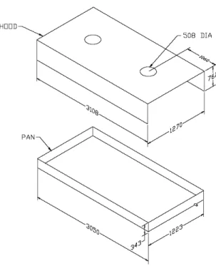
Four industrial oil cooker mock-ups were built for the research program. They were used to investigate the impact of oil cooker sizes on the performance of water mist. The oil cooker mock-up consisted of a pan and a hood. Both ends of the hood were open. The schematics of four mock-up #1 through #4 are shown in Figures 1 to 4.
The pans of the oil cooker mock-ups #1 to #3 had the same width (1.22 m) and depth (0.343 m), but their lengths were 1.22 m, 3.05 m and 4.57 m, respectively. Their hoods also had the same width (1.27 m) and depth (0.76 m) but the lengths of three hoods were 1.27 m, 3.10 m and 4.62 m, respectively. There were holes with a
dimension of 0.508 m diameter on top of the hood to simulate the connection with the exhaust duct. The number of holes on top of the hood was determined according to the length of the hood.
Figure 1. Schematic of industrial oil cooker mock-up #1 (dimensions in the figure are in mm)
Figure 2. Schematic of industrial oil cooker mock-up #3 (dimensions in the figure are in mm)
Mock-up #4 pan was 3.0 m long, 2.4 m wide and 0.343 m deep. Its hood was 3.05 m long, 2.6 m wide, and 0.76 m deep. There was a 0.508 m diameter hole on top of the hood at the center. The distance from the center of the hole to either end of the hood was 1.5 m.
Figure 3. Schematic of industrial oil cooker mock-up #3 (dimensions in the figure are in mm)
Figure 4. Schematic of industrial oil cooker mock-up #4 (dimensions in the figure are in mm)
1525
2600 3050
2400
3000
During the experiments, the effect of the hood position in the oil cooker on the water mist extinguishing performance was also investigated. The hood was placed in two different positions: a hood-up and a hood-down position. The clearance of the gap
between the hood and the pan was 0.46 m at the up position and 0.05 m at the hood-down position.
A propane burner was used as the heating source for the mock-ups. The burner was centered beneath the pan, distributing the heat uniformly throughout the pan surface. 3. INSTRUMENTATION
A number of instruments were used in the experiments to monitor the water mist discharge and fire suppression process. They were thermocouples, pressure gauges, heat flux meters, oxygen analyzers, water flow meters and video cameras.
For experiments involving industrial oil cooker Mock-ups #1 to #3, a number of thermocouple trees was used to measure oil and flame temperatures. The thermocouple trees were placed along the centerline of the mock-up. Each thermocouple tree had two thermocouples that were located, respectively, 5.1 cm and 10.2 cm above the bottom of the pan. The number of thermocouple trees and their locations in the pan were determined by
the size of the oil cooker mock-up. One thermocouple tree was used in the tests with Mock-up #1 to measure the oil temperatures. It was located at 0.61 m from the edge of the pan. Four thermocouple trees were used in the tests with Mock-up #2 to measure the oil temperature. They were located at 0.61 m intervals starting at 0.61 cm from the end of the pan. One extra thermocouple was placed at Thermocouple tree #2 and 0.22 m above the bottom of the pan, which was used to determine the oil ignition temperature and ignition time. Seven thermocouple trees were used in the tests with Mock-up #3. They were located at 0.61 m intervals starting at 0.45 m from the end of the pan. Also, one extra thermocouple was placed at Thermocouple tree #2 and 0.22 m above the bottom of the pan, which was used to determine the oil ignition temperature and ignition time.
For experiments involving Mock-up #4, three thermocouple trees were placed in the pan to measure oil temperatures and air/flame temperatures above the oil surface.
Thermocouple tree #1 was placed in the center of the pan and Thermocouple trees #2 and #3 were located 0.7 m apart from each other along the direction from the center of the pan to the southeast corner of the pan. Eight thermocouples (Type K, 18 gauge) were attached to each tree. The elevation of each thermocouple was 51 mm, 100 mm, 124 mm, 165 mm, 254 mm, 381 mm, 681 mm and 981 mm, respectively, above the bottom of the pan, when the oil depth was 127 mm.
Two pressure gauges were used to monitor the discharge pressure of the water mist system. The first one was located in the inlet of the water mist piping system and another was located near one of the nozzles. The real discharge pressure was determined based on the data measured near the nozzle.
Two heat flux meters (air-cooled) were used to measure the heat release rate of the fire and to determine if fire flare-ups were generated during the suppression. The heat flux meters were located 0.5 m away from the pan and 1.2 m and 1.90 m, respectively, above the floor.
Three video cameras were used in the experiments to record the testing process and to assist in the identification of the water mist discharge time as well as the fire extinguishing time. One was located at the southeast side of the cooker, the second at the west side of the cooker, and the third was an aerial-view camera and elevated 7 m from the ground of the east side of the cooker.
One O2 analyzer was used to measure the O2 concentration in the compartment.
The sampling port was located at the east side of the up, 1 m away from the mock-up and 0.05 m above the edge of the pan.
One flow meter located in the inlet of the water mist system was used to measure the water flow rate of the water mist system. The locations of thermocouples, pressure gauges and water flow meter are shown in the schematic of the instrumentation (see Figure 5).
During the experiments, all testing data, including temperature, pressure, heat flux and water flow rate, were collected by a data acquisition system.
Figure 5. Schematic of instrumentation in the fire tests
4. EXPERIMENTAL PROCEDURE
Canola oil was used as the cooking oil in the experiments. The properties of the canola oil are listed in Table 1.
Table 1. Physical Property of Canola Oil [2, 4]
Oil Flash Point
(K) Auto-ignition temperature (K) Density (kg/L) Specific heat (kJ/kg.K) Heat release rate (MW/m2) Canola 505-563 603-633 0.914 1.91 1.81
Fresh cooking oil was introduced into the pan for each experiment and then heated continuously at 5-8oC/min until it auto-ignited. After the flame had spread over the whole oil surface, the fire was allowed to burn freely for 30 seconds. At the end of the pre-burning period, the water mist discharge was activated manually. After the fire was extinguished, the discharge of water mist was maintained for a certain time period to cool the cooking oil and prevent re-ignition.
During approving experiments, the performances of the water mist system were evaluated with three sizes of industrial oil cooker mock-ups. There were two
experiments for each size of industrial oil cooker mock-up associated with two different hood positions. Water mist system components, their locations and operating
5. ACCEPTABLE PERFORMANCE CRITERIA
Based on FM Global fire testing protocols [1], some acceptable performance criteria for using a water mist system for industrial oil cooker protection are:
1. The water mist system shall be capable of extinguishing any auto-ignition fire inside the industrial oil cooker mock-up, regardless of its hood position; 2. All open flames shall be extinguished within one minute;
3. The average oil temperature shall be cooled down to 200oC at the end of water discharge;
4. The water mist system discharge shall not exceed 30 minutes;
5. During the discharge of the water mist system, there should be no excessive fire flare-ups, micro explosions of oil reacting with water, or splashing of burning oil. 6. WATER MIST SYSTEMS
Water flux, spray coverage and spray momentum were considered to be the three most important characteristics of water mist required for extinguishing a cooking oil fire [3]. To develop an appropriate water mist system, water mist characteristics of both single and group nozzles of water mist systems, including their drop size, spray angle, water density distribution and water flow rate, were studied in the experiments.
For spray experiments involving a single nozzle, the nozzle was placed 1.0 m above the floor. A number of sampling cups with a 7.2 cm diameter were placed on the floor starting from the center of the spray coverage along the longitudinal, transverse and diagonal axis to measure the water density distributed in the coverage area. The distance between the cups was 20 cm. The amount of water collected by the cups was weighed after the discharge. The change in spray angle with discharge pressure was recorded and measured by a digital camera and a digital video camera.
For the spray performance of the water mist system in the oil cooker, 23 sampling cups were placed on the floor of the pan to measure the water density distribution in the pan. They were distributed from the center of the pan along the longitudinal, transverse and diagonal axis of the pan. The distance between the cups was 20 cm. The amount of water collected in the cups was weighed after the water mist discharge. The total amount of water collected in the pan was determined by measuring the water depth in the pan. The water collection ratio in the pan was defined as the ratio of total water collected in the pan to the total water discharged by the water mist system.
Two water mist fire suppression systems were developed in the research program, based on their spray characteristics. Fire suppression performances of two systems were investigated in the experiments.
4.1 Water Mist System I
Water mist system I consisted of a number of MistShield nozzles and a piping system. The water flow rate of the MistShield nozzle ranges from 30 L/min at 414 kPa to 40.9 L/min at 862 kPa discharge pressure. Water drops generated are relatively fine (see Figure 6). Under a pressure of 5.52 bar (80 psi), its 50 and 90 percentages of the spray volume contained in drops are smaller than 250 and 380 microns, respectively. The spray angle of the nozzle is150 degrees and not changed with an increase in discharge pressure. The water spray generated by the MistShield nozzle can cover an area of 2.8 m diameter at 1.0 m below the nozzle. The water density distributed in the coverage area was not uniform, but decreased with the distance from the spray center. When the discharge pressure was increased, the water density at the center of the spray cone was substantially increased, while the water density near the edge of the spray cone had a minor increase. Its spray coverage area did not change with a change in the discharge pressure.
For the protection of an Industrial oil cooker, the nozzles of water mist system #1 were installed inside the cooker mock-up and placed 0.93 m above the bottom of the pan. The maximum area that could be protected by a single MistShield nozzle was 1.22 m wide x 1.22 m long and was extended to 1.22 m wide x 1.52 m long in a multiple-nozzle
application. The number of nozzles installed in an oil cooker was determined by the size of the cooker. Water mist generated by system I was able to cover the whole oil pan surface. Under 414 kPa discharge pressure, approximately 84.2% of the water discharged from water mist system I was collected by the pan and the average water density in the pan was 13 L/min.m2.
Figure 6. Water spray of a single nozzle of water mist system I
Figure 7. Water spray of a single nozzle of water mist system II
4.2 Water Mist System II
Water mist system II consisted of a number of WL nozzles (see Figure 7) and a piping system. The water droplets generated are relatively coarser, compared to water mist system I. Under a pressure of 5.52 bar, its 50 and 90 percentages of the spray volume contained in drops are smaller than 300 and 540 microns, respectively. Its water
flow rate varies from 17.4 L/min at 414 kPa to 24.3 L/min at 862 kPa discharge pressure. Its spray angle is substantially decreased with an increase in discharge pressure. Its 120 degrees of the spray angle at 207 kPa of the discharge pressure decreases to 80 degrees as the discharge pressure increases to 896 kPa. This resulted in a decrease in the spray coverage area with an increase in discharge pressure.
The nozzles of water mist system II were installed inside the cooker mock-up and placed 1.03 m above the bottom of the pan. The spacing of the nozzles was 1.22 m x 1.00 m. Its water spray was also able to cover the whole oil pan, however, its spray pattern was different from that observed in water mist system I. High water density appears underneath the nozzle, and the water density near the edge of the pan is higher than that with water mist system I, but the water density in the center area of the pan along the longitudinal direction is lower than that with water mist system I.
The water collection ratio in the pan produced by water mist system II was lower than that with water mist system I. Under 414 kPa discharge pressure, its water
collection rate was 80.4% and its average water density in the pan was 11.5 L/min.m2. With an increase in discharge pressure, the water collection ratio and the average water density in the pan were increased, and the water distribution pattern was changed. The water delivery density along the longitudinal direction tended to be uniform, while the peak water delivery density along the diagonal direction was shifted towards the edge of the pan.
6. FIRE EXPERIMENTS
The extinguishing performances of two developed water mist systems were evaluated in the fire experiments by using different sizes of industrial oil cooker mock-ups with different hood positions, discharge pressures and oil depth. The discharge pressure employed in the experiments ranged from 414 kPa (60 psi) to 689 kPa (100 psi) for water mist system I, and from 689 kPa (100 psi) to 827 kPa (120 psi) for water mist system II.
During the experiments, fresh canola oil was heated continuously. After the oil was heated over 250oC, smoke appeared over the oil surface. The smoke and fuel vapour became very dense near the auto-ignition temperature. The oil auto-ignited at
temperatures ranging from 343oC to 361oC during the experiments. The flame consumed all the fuel vapour over the oil surface that was generated in the heating period and quickly spread to the whole oil surface. During free burning, the fire was fully
developed, filling inside the cooker and reaching outside the oil cooker. A large amount of dark smoke was produced. The flame temperatures were high at the center of the oil pan and they decreased with an increase in distance from the center of the oil pan.
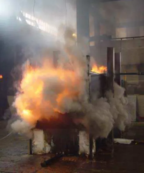
Full-scale experiments showed that both water mist systems I and II very effectively extinguished all the large cooking oil fires in the experiments. With the discharge of water mist, the flame below the nozzle tip was quickly extinguished and dark smoke disappeared from the cooker as fine water drops absorbed the heat from the
hot oil and produced a large amount of steam (Figure 8). The entire flames in the oil cooker were completely extinguished after a certain period of water mist discharge.
The extinguishing performance of the two water mist systems was dependent on the discharge pressure, oil cooker size, hood
position, but not on the oil depth in the pan. For water mist system I involving four industrial oil cooker mock-ups and various operating conditions, its extinguishing time ranged from 3 to 11 seconds, while for water mist system II involving Mock-up #4, its extinguishing time ranged from 15 to 18 s. No excessive fire flare-up was produced and no burning oil was splashed outside the cooking equipment during fire suppression.
Figure 8. A cooking oil fire was suppressed by water mist system I (Mock-up #3) Water mist system I was more effective in
extinguishing a cooking oil fire than water mist system II due to its large spray angle and relatively uniform water density distribution. Under a discharge pressure of 689 kPa (100 psi), water mist system I extinguished the oil fire occurring in Mock-up #5 in 4 seconds, while it took 15 s
for water mist system II to extinguish the same fire size.
An increase in the discharge pressure resulted in an increase in the water flow rate and spray momentum. For water mist system I involving Mock-up #4, an increase in discharge pressure from 414 to 689 kPa reduced extinguishing time from 7 to 4 seconds. However, for water mist system II, an increase in the discharge pressure from 689 to 827 kPa resulted in an increase in extinguishing time from 15 to 18 seconds due to the change in the distribution of water density over the oil pan. It suggested that the performance of the water mist system might not be improved with an increase in discharge pressure, depending on changes in other important water mist characteristics.
The hood position had an impact on the extinguishing performance of the water mist system. For all the fire experiments conducted, the fire grew more quickly at the hood-down position than at the hood-up position, as more heats were confined inside the oil cooker. However, the extinguishing time was substantially reduced, when the hood was placed from the ‘up’ position to the ‘down’ position. This is because the amount of hot gases and flames accumulated near the ceiling that could not be hit by water mist was reduced with the hood in the “down” position.
The oil cooker size also had an impact on the water mist performance. Under the same discharge pressure of 689 kPa with the hood at the “down” position, the
extinguishing time was reduced from 5 to 3 seconds with an increase in the size of mock-ups from Mock-up #1 to 3 Mock-up #3., while the extinguishing time was the same (11 seconds) for both Mock-ups #1 and #3, when the hood was at the ‘up’ position.
Time (s) 1640 1660 1680 1700 1720 1740 1760 1780 1800 Oil T e mperat ure ( oC) 200 220 240 260 280 300 320 340 360 380 5.1 cm (#1) 10.2 cm (#1) 5.1 cm (#2) 10.2 (#2) 5.1 cm (#3) 10.2 cm (#3) 5.1 cm (#4) 10.2 cm (#4) 5.1 cm (#5) 10.2 cm (#5) 5.1 cm (#6) 10.2 cm (#6) 5.1 cm (#7) 10.2 cm (#7)
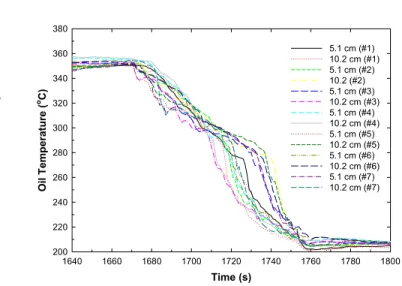
Figure 9. Variation of oil temperatures measured at different locations of the oil pan with time During fire suppression, water mist also demonstrated a strong cooling effect on hot oil. For water mist system I, average oil cooling rates, which was defined as the ratio of temperature difference between oil ignition temperature and cooled oil temperature at the end of water mist discharge to the duration of water mist discharge, were ranged 86.6oC/min to 109oC/min, depending on the water mist discharge pressure, or water quantity discharged onto the oil.
Figure 9 shows the variation of oil temperatures with the time involving water mist system I. The average oil temperature was cooled down to 200oC from its burning temperature during approximately 95 seconds of water mist discharges under a discharge pressure of 689 kPa. Since the cooking oil was effectively cooled down, no re-ignition was observed in the experiments involving the two water mist systems.
7. SUMMARY
Testing facilities with four large industrial oil cooker mock-ups were built for the project and they could be used for studying/approving a water mist fire suppression system for industrial oil cooker protection. Performances of two water mist systems developed in this project were evaluated in the full-scale experiments. They both
effectively extinguished large cooking oil fires and cooled hot oil below to 200oC from its burning temperature. No re-ignition occurred in the oil pan. Water mist discharge did not cause excessive fire flare-up or splash burning oil outside the cooker. The
extinguishing performance of water mist was dependent on the type of water mist system, discharge pressure, oil cooker size and the hood position.
This work provided information on the characteristics of cooking oil fires and performance of water mist in extinguishing such types of fires. It also provided technical data into testing methodologies to evaluate water mist fire suppression systems for industrial oil cooker protection.
8. ACKNOWLEDGEMENTS
The authors would like to thank Drs. Soonil Nam, Hong-Zeng Yu, Mr. L. B. King of FM Global for their technical assistance to the projects.
1 Factual Mutual Research Corporation, “Draft Performance Requirements for Water Mist Systems for the Protection of Industrial Oil Cookers,” May 2003. 2 Soonil Nam “Application of Water Sprays to Industrial Oil Cooker Fire,” 7th
International Symposium on Fire Safety Science, Massachusetts, USA, June 2002.
3 Liu, Z.G.; Kim, A.K.; Carpenter, D.W. "Extinguishment of large cooking oil pool fires by the use of water mist systems," 2004 Combustion Institute/Canadian Section Spring Technical Meeting, Kingston, Ontario, May 09, 2004.
4 Przybylski, R., “Canola Oil: Physical and Chemical Properties,” Canola Council of Canada Publication, www.canola-council.org, 1999.