Design of a Small-Scale Continuous
Linear Motion Pharmaceutical Filtration Module
byKatherine Wing-Shan Wong
Submitted to the
Department of Mechanical Engineering in partial fulfillment of the requirements for the Degree of
Bachelor of Science at the
Massachusetts Institute of Technology
ARCVES
MASSACHUSETTS INSTITUTE OF TECHNOLOGYJUN 3 0 2010
LIBRARI ES
June 2010 C 2010 Wing-Shan Wong All rights reservedThe author hereby grants to MIT permission to reproduce distribute publicly paper and electronic copies of this thesis document in any medium now known or hereafter created.
and to
in whole or in part
Signature of Author... .. ...
Departnv o Mepanico Enginee
May 2,20 10
C ertified by... . ...
Mar eper
7
sociate Professor of Mechanical Engineering Thesis SupervisorAccepted by... .. .... . . ...
John H. Lienhard V Collins Professor of Mechanical Engineering
Design of a Small-Scale Continuous
Linear Motion Pharmaceutical Filtration Module
byKatherine Wing-Shan Wong
Submitted to the Department of Mechanical Engineering on May 20, 2010 in partial fulfillment of the
requirements for the Degree of Bachelor of Science in Mechanical Engineering ABSTRACT
A new small-scale continuous linear motion pharmaceutical filtration prototype was designed, fabricated, and tested. The goal of this unit is to filter an Active Pharmaceutical Ingredient (API) from a mixture of API molecules, ethyl acetate, and possible contaminants. This unit is important in the development of a small-scale continuous pharmaceutical manufacturing process by Novartis, which would lower costs and increase product flexibility and production. A compliant blade is mounted onto a linear guide assembly and driven by a stepper motor to filter the API mixture through a porous metal filter. The mixture enters into the middle of the filtration unit; the excess ethyl acetate and dissolved contaminants are pulled through the filter by a vacuum pump, leaving the desired API molecules on the filter surface. The API is then moved across the filter by the blade to output collectors at either end. The unit itself takes up 0.03 cubic meters, an eighth of the size of the current equivalent production model. This unit has been tested to successfully filter the API from the rest of the mixture and will help determine if a rotary or linear style filtration system should be used as the final design.
Thesis Supervisor: Martin Culpepper
ACKNOWLEDGEMENTS
I would like to thank Professor Martin Culpepper for his guidance this past year and for this project opportunity. He is only slightly terrifying at times, but in the best motivational way possible; his persistence and dedication to his projects and students is admirable and he has taught me a lot. Thanks to Alex Slocum Jr. for his engineering consultation and Jonathan Hopkins for his mentorship in the design phase, incorporating me into design of the rotary module, and for being a liaison to the Chemical Engineering and Novartis teams. I would also like to thank those on Chemical Engineering task force: James Evans for answering all my questions regarding the new manufacturing process, Salvatore Mascia for directing the chemical side of the process, Haitao Zhang in handling the logistics behind the chemical equipment in this module, and Justin Quon for providing the solutions used in these experiments.
TABLE OF CONTENTS
Chapter 1: Introduction...10 1.1 B ackground ... 11. 1.1.1 Pharmaceutical Production...11 1.1.2 Material Filtration...13 1.1.3 M aterial Properties... 141.1.4 Continuous Small-Scale Rotary Filtration... 15
Chapter 2: Device Specifications...16
2.1 K ey Functions ... 16
2.2 C ontinuous... 16
2.3 M odular... . . 17
2.4 C om pact... . . 17
2.5 C oncept Iterations... 17
2.5.1 Belted Blade Design... 18
2.5.2 Four Bar Linkage Design... 19
2.5.3 Rotary-Vane Blade Design... 20
2.5.4 Auger Design... 21
2.5.5 Lead Screw Design... 21
2.5.6 Linear Guide Design... 22
Chapter 3: Mechanical Design...23
3.1 Complete Filtration Unit Assembly... 23
3.3 M etal Filter... 26
3.4 Fluid C ontainm ent... 28
3.5 D rive System ... 30
3.5.1 B lade... . .. 30
3.5.2 Linear G uide B lock... 32
3.5.3 Linear Guide Rail and Spacer... 33
3.5.4 Synchromesh Drive...33
3.5.5 Pulley M ount...34
3.5.6 M otor M ount...36
3.5.7 M otor... . 37
3.6 Outer Box Structure...39
3.7 V iew ing W indow ... 40
C h ap ter 4: R esults...42 C hapter 5: C onclusions...46 5.1 Future W ork... 47 5.2 Things L earned... 47 R eferen ces... . .. 50
LIST OF FIGURES
Figure 1: Complete Linear Filtration Device Setup ... 1 1 Figure 2: Downstream Process Flow Chart... 12Figure 3: Existing Batch Filtration Modules ... 14 7
Figure 4: Traditional Circular Filter ... 14
Figure 5: Continuous Small-Scale Rotary Filtration Module... 15
Figure 6: Overall System Functions ... 18
Figure 7: Rotary Belt Design... 18
Figure 8: Four-Bar Linkage Design... 19
Figure 9: Rotary-Vane Pump... 20
Figure 10: Rotary-Vane Blade Design... 20
Figure 11: Linear Guide Design ... 22
Figure 12: Complete Linear Filtration Unit... 24
Figure 13: Fluid Waterfall ... 25
Figure 14: Fluid Waterfall Output Alternative ... 25
Figure 15: Metal Filter...27
Figure 16: Microscopic Photograph of Filter Pores... 27
Figure 17: Fluid Containment Module ... 28
Figure 18: Top View of Fluid Containment Module... 29
Figure 19: Detail of Fluid Containment SPP 100 Outlet... 29
F igure 20: D rive System ... 30
Figure 21: Detailed View of Linear Guide Assembly ... 32
Figure 22: Linear Guide Assembly... 33
Figure 23: Capstan Drive Pulley and Synchromesh Close-Up View ... 34
F igure 24 : Pulley M ount ... 35
Figure 25: Slots in Pulley Mount and Outer Box Structure for Cable Tensioning... 35
Figure 26: Motor Mount - Side View ... 36
Figure 27: Figure 28: Figure 29: Figure 30: Figure 31: Figure 32: Figure 33: Figure 34: Figure 35: Figure 36:
LIST OF TABLES
T able 1: M otor Sizing ... 39
Motor Mount - Bottom View... 37
Motor Torque-Speed Curve ... 38
Outer Box Structure - Isometric View... 39
Outer Box Structure - Bottom View... 40
V iew ing W indow ... 40
Detail of Interface between Viewing Window Notch and Outer Box Structure... 41
Filtration Unit Fume Hood Setup... 42
Scraping over Accumulated Mother liquor Pool... 44
Scraper Blade and API Filtration ... 44
CHAPTER
1
INTRODUCTION
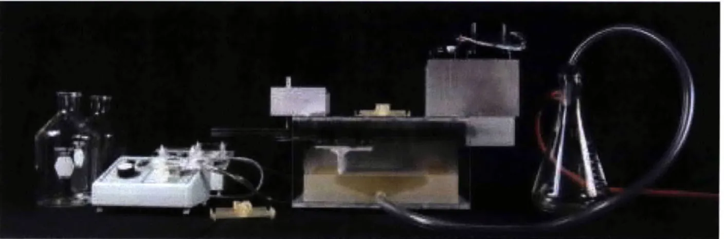
The purpose of this project is to design a filtration unit to be used in a continuous linear small-scale pharmaceutical manufacturing process for Novartis. The overarching goal of this project is to prove that pharmaceutical production is not limited to large-scale batch processes, but can be applied to a small-scale method that is both continuous and modular-a system which has never before been successfully implemented. Developments in this new method will allow for increases in flexibility in pharmaceutical manufacturing, benefiting both consumer and company. This ensures that safe, high quality drugs get to patients faster and at a lower cost than ever before. Additional benefits for the consumer can be found in the form of new small-volume drugs for those with less common ailments. This form of pharmaceutical personalization will decrease the number of potential side effects and increase the patient's quality of life. On the company side, it will increase product flexibility, but reduce the asset footprint, capital expenditure, operational cost, raw material, inventory, and product development time. The decreased cycle time allows the system to be a lot more time efficient in dealing with errors in manufacturing. Generally if an error occurs, the company must quarantine the entire manufacturing line until the error has been flushed out of the system. The continuous manufacturing method will decrease this quarantine from 6 months to 10 days and lower manufacturing costs by a predicted 60%. Thus, finding a way to implement a small-scale continuous pharmaceutical manufacturing model will have much impact on the future of pharmaceutical production and improve the quality of lives for those around us.The linear filtration module is shown in Figure 1 and is capable of filtering a mixture of the Active Pharmaceutical Ingredient (API), ethyl acetate, and dissolved waste, so only the API remains. The exact throughput under steady-state industry-standard conditions or the moisture content of the output API has yet to be measured, but initial performance shows that this module is on track to performing at the required 1 L per hour.
Figure 1 Complete Linear Filtration Device Setup
1.1 Background
1.1.1 Pharmaceutical Production
Pharmaceutical manufacturing is traditionally performed through large-scale batch processes to increase efficiencies and reduce costs. In this project, the active pharmaceutical ingredient (API) is SPP100, a monotherapy treatment for hypertension. This production begins with the upstream processes that focus on API synthesis, creating a mixture of API and bulk solvent (ethyl acetate) in a solution generally referred to as the "mother liquor." This is then followed by the downstream processes, which focus on the drug product formation-API purification, crystallization, filtration, drying, pill formation, and packaging. The crystallization process attempts to purify the mother liquor by isolating pure SPP100 molecules into a crystal form while the ethyl acetate solvent dissolves any remaining contaminants. The filtration process attempts to filter the SPP100 molecules from bulk solvent and wash the SPP100 molecules to remove contaminants. Material is then dried into a powder by heating modules. The filtration process must occur in a refrigerated state ranging from -20'C to 00C. Therefore,
the temperature differential between the two modules is also an important design consideration in ensuring the modules are compatible. After drying the API comes pill formation, which can be performed with multiple methods, such as roller compaction or extrusion from the powder formed in the heating units. A figure of the downstream process along with the multiple methods of pill formation can be found in Figure 2. [1]
Legnend 90% SPP100, 10% MCC, 50% ethyl acetate
blender wet extrusion rotary dryer
60% SPP100, 40% PEG
(or 40% HPC)
blender L melt extrusion conveyor cooling
=W10 Compulsory all streams amb 'Option 5: Direct extrusion am* Option 1: Wet Extrusion
mm* Option 2: Melt extrusion Option 3: Roller compaction Options 1, 2, and 3
Option 4: Thin film 10 Split * Merger .. Integrated Unit I _ - -_ - -_ API from Upstream Pure solution from upstream Tablets
Commercially, the traditional batch process is broken down into multiple sites, with an approximate total square footage of 10,000 square meters and cycle time of 6 months. The small-scale continuous process, on the other hand, will be a single chain at one location, with an estimated size between 1,000 - 5,000 square meters. The small-scale continuous process will also have a dedicated manufacturing line per compound and is expected to run 50 weeks per year. In addition, the smaller scale also corresponds to a lower cycle time of approximately 10 days as compared to 6 months in a batch process.
This new system will reduce capital costs, with less expensive machines needed to produce pharmaceuticals, and facilitate the integration of compliance and quality within the process-a 40-50% reduction in the asset footprint, a 25-60% reduction in capital expenditure, and a 25-60% reduction in operating costs. Other benefits of this revised system are the flexibility in supply size, the further reduction of raw material and intermediate inventories, as well as the reduction of overall drug substance and drug product development times, improving the time to market and assuring the availability of high quality, safe and efficacious drugs to patients. [2]
1.1.2 Material Filtration
The goal of the material filtration is to remove the bulk solvent and dissolved impurities from the mother liquor. Traditionally in a batch process, the size of the process is highly dependent upon the desired input and output of the entire system. An example of the existing module is seen below in Figure 3. The mother liquor is poured into a cylindrical container with a bottom composed of a circular filter, shown in Figure 4.
The type of filter is dependent upon the process, with different mother liquors necessitating different filters, such as ceramic frit, paper, or cloth filters. A vacuum pulls the mother liquor through the filter, removing the bulk solvent and dissolved waste. After this first step, a final cleaning using a second ethyl acetate wash is poured over the filtered solute to further dissolve any remaining impurities. Once the two washes are completed, the machine must be stopped, the SPP 100 molecules removed and then placed in the drying unit, making it a disjointed system with substantial down-time between steps.
Figure 3 Existing Batch Filtration Modules [3]
Figure 4 Traditional Circular Filter [3]
1.1.3 Material Properties
The mother liquor solution of interest in this thesis is a blood pressure medicine internally referred to as "C13." It is composed of SPP100 molecules, 95% ethyl acetate, and 5% ethanol. For experimental purposes, the chemical engineers at MIT who are also working on the Novartis Project have developed a solution known as "C1O," composed of SPP100 molecules and 100% ethyl acetate.
1.1.4 Small-Scale Continuous Rotary Pharmaceutical Filtration
A rotary small-scale continuous filtration module, shown in Figure 5 has been previously built by PhD candidate Jonathan Hopkins.
Figure 5 Continuous Small-Scale Rotary Filtration Module
The blades rotate in a counter clockwise direction and the mother liquor is pumped into the system at the "twelve-o-clock" position whereas the ethyl acetate wash is pumped further downstream at the "nine-o-clock" position. The API is then filtered and outputted at the "three-o-clock" point whereas the waste is vacuumed through the filter and deposited in a waste reservoir.
As opposed to the traditional batch processes, this rotary system is fully continuous, but compatibility with upstream and downstream processes is unclear, so it is important to explore the functionality of a linear system. This unit is designed to sit on top of the heater unit, yet complications arise given that the filtration process must be refrigerated. In addition, the modularity and flexibility in expanding the capacity of the processes capable in the rotary system is limited. If one were to scale the system, complications arise in the blade assembly and function. Considering the blades are only constrained at the center of the system, increasing length would result in increased blade deflection and a magnification of the variable blade speeds along the length of the blade. In this sense, the linear system is more uniform when scaled.
CHAPTER
2
DEVICE SPECIFICATIONS
In order for this machine to be useful, there are some fundamental system functions that must be considered.
2.1 Key Functions
Looking at the machine's functionality from a rather simplistic standpoint, what really matters is what goes in and what comes out. The input of such a system is the mother liquor, a pharmaceutical slurry composed of ethyl acetate solution, SPP100 crystals, and potentially unknown contaminates. The desired output that we care about is the cake of SPP100 molecules. To put this into perspective, one can imagine the input as skim milk laced with white powder and the output as a wet cake of that powder with thick consistency resembling a slice of polenta. To get to the desired output consistency, this slurry goes through two stages as outlined in Section 1.1.2. This system must be able to process 1 L of mother liquor per hour, corresponding to 1 OOg of API per hour.
2.2 Continuous
This system must be able to run at a minimum of 250 days of the year, and is expected to run continuously for an expected 350 hours before maintenance or material switch. In order to do so, the system must be carefully designed to ensure the input and output of materials are independent from the active filtration process, that components can be easily replaced for repair (encompassed in the modularity requirement in the next section), and that it is compatible with processes immediately upstream and downstream.
2.3 Modular
Looking at the purpose of the filtration module in the context of the big picture of the system, it must modularly fit with the upstream and downstream processes to enable increased flexibility. Different pharmaceutical compounds have different process parameters and need different settings, such as filtration time, which is partially related to filter size in a continuous mode. An overall modular architecture within the system ensures that the filtration module is adaptable with other modules.
Looking more closely at the filtration unit itself, exact process parameters are still unknown for a continuous process. For example, the most efficient scraper blade material or angle and filter material are all unspecified. To accommodate these uncertainties, it is important that the system remain flexible. This is accomplished by having modular components within the filtration unit that can be easily adjusted or changed. Such flexibility will also facilitate maintenance in the long run.
2.4 Compact
Given that this new manufacturing system is designed to be small-scale and fit in a small space, the filtration module must conform to the "as small as possible" size constraint. An upper limit was defined by the client as being no larger than 0.23 cubic meters, which is the size of the existing filtration unit used in small-scale batch processes. [2]
2.5 Concept Iterations
Prior to choosing the current mechanical design, many alternative concept iterations were explored to ensure that an effective solution was chosen. To stimulate creativity and think of as many plausible solutions as possible, the filtration process was generalized as a big black box that would transfer material (as shown in Figure 6). With this thought process, imagination was set loose to generate new and crazy concept ideas that led to the module's current form.
Input 1 Input 2
- - + Output
Figure 6 Overall System Functions
2.5.1 Belted Blade Design
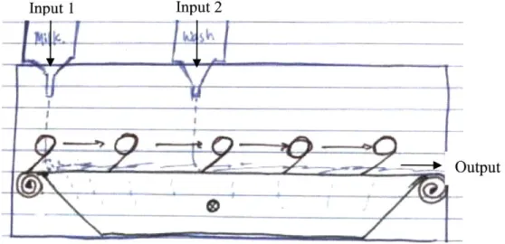
As the most logical step in linearizing Hopkins' rotary system, the blades were transformed from a horizontal rotary motion to a vertical linear rotation as shown in Figure 7. The inputs would be placed as close to the filter as possible to refine the drip point as well as increase the amount of solution that reaches the filter by avoiding dripping on the blades while they are at the top. The output would be swept by the blades off to the right and deposited in the downstream module.
- Input 2
Benefits of such a system are that it can be easily implemented considering a similar design has been already proven to work. This linearized design is rather inefficient given that only half the blades are in constant use; these extra parts increase the necessary occupied space as well as system complexity and part count.
To simplify these issues, a timing belt was tested as a possible combined blade and chain mechanism. Belts with a blade length of 6.35 mm and 12.7 mm pitch proved too short and caused the slurry to be displaced to the side out of the belt, rather than be translated along the length of the filter. In order to obtain an appropriate blade length, food-grade inclined conveyor belts with 38.1 mm blades were used. The pitch of these belts was 457.2 mm, which is too large to be useful.
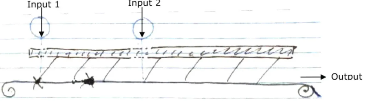
2.5.2 Four Bar Linkages
The four bar linkage version played on improving the belted blade design. It would eliminate the unused repeated parts as well as the space at the top that would otherwise be occupied by the returning blades. The four bar linkage necessitates a forwards linear motion to translate the material and an elliptical return motion to return the blade to origin without contacting the filter and material. This path proves rather difficult to recreate and would ultimately take up as much space as the belted blade design given the potential size of the motion
and the potential size of the drive mechanism.
Input 1 Input 2
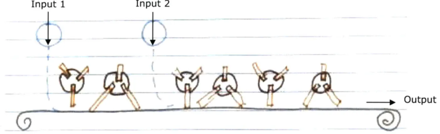
2.5.3 Rotary- Vane Blade Design
The previous two concepts involved moving blades, so using reciprocity, this concept focused more on how to make the blades "stationary" and based off of nodes. Inspiration was also drawn from the research of vacuum pumps for the system. Rotary vane pumps displace volume within the pump, so this displacement mechanism (Figure 9) was applied to pushing fluid along a flat filter.
\ r I
Figure 9 Rotary-Vane Pump
The rotary vane mechanism was chosen over a simple rotating blade to ensure that material did not get stuck between nodes. To make sure this didn't happen, the blades at each node would have to overlap scraping areas (Figure 10). This would be achieved with the rotary vane mechanism given that there is the spring to allow for this change in distance.
Input 1 Input 2
4.
Output
This would make the unit much more compact as compared to the previous system, but the part count and part complexity of such a system would be a nightmare. The parts could potentially be taken from existing pumps, but the price of doing so or creating a custom mechanism would be exorbitant.
2.5.4 Auger Design
In researching all the various filter options, the dominant metal filter shape available was a cylinder. Thus, another concept design was focused around this resource, where a hollow cylindrical filter would be held horizontally, rigidly fixed in space, and an auger would slowly spin concentric and translate the material along the filter walls.
Concerns with this design include complications in implementing the vacuum pull considering it would have to accommodate the cylindrical shape and input ports for both the mother liquor and ethyl acetate wash. In addition, augers typically translate material via displacement, which means that the viscous and sticky substance would get clogged in the helical flights and there would be minimal contact with the filter.
2.5.5 Lead Screw Design
An alternative concept was to try to minimize the number of parts by having one blade move in a simple back and forth motion. A simple implementation is to use a lead screw to drive a carriage back and forth; inspiration for this concept was drawn from Professor Culpepper's 2.72 Elements of Mechanical Design class.
Compared to the other systems, this design is more simplistic, has a lower part count, and is much more compact. A functional concern arises if the input were on one side and the output at the other. To obtain a proper sweeping motion, the blade must consistently start before the input port. Yet, given that there is only one blade and on the return it is constantly scraping the filter, the wash would be pushed into the pre-filtered mother liquor and there would also be a lot of material stuck on one side of the blade and a lot of material stuck and pushed to one side. In order to get around this issue, a system was designed with a central input and two side outputs. This would maintain the required filtration order as well as conserve space and utilize the backwards return motion to produce additional output.
The primary concern with this design is the high force loads on the lead screw by the carriage, which could possibly lead to bowing in the screw. Secondarily, is the needed variability in travel speed. For rapid travel, the lead screw would have to have a large pitch and we would decrease the amount of force given a constant motor torque (1).
Fl = 27t (1)
Although this design is completely plausible and within the realm of reality, there is a simpler way to achieve the desired motion.
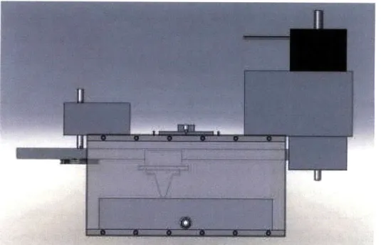
2.5.6 Linear Guide Design
The lead screw design was taken and replaced with a linear guide assembly driven by a stepper motor and Synchromesh pulleys and cable. This final concept (Figure 11) was simpler yet had the same design merits as the lead screw design. Here, we do not need to worry about screw alignment, effects of bowing, or carriage speed. A linear guide can withstand high normal forces on the guide, so it would be simple to get good blade-filter contact, especially with a compliant blade.
CHAPTER
3
MECHANICAL DESIGN
The following subsections document the thought process and considerations in designing and building each module. This section is organized based upon the substance flow from input to
output and relevant modules to make that process possible.
3.1 Complete Filtration Unit Assembly
The complete assembly is shown below in Figure 12, with the material flow from left to right. At the left are two glass reservoirs, one of which holds the mother liquor and the other the ethyl acetate wash. Peristaltic pumps control the flow rates of these two solutions into the system. The solutions enter the system through the fluid waterfall, located at the center on top of the outer box extrusion, and fall onto the metal filter. A vacuum pump is drawing air and waste (contaminates and excess ethyl acetate) through the filter, through the central hole of the fluid containment system to the flask on the right. This setup is designed so the red hose can pull a vacuum while the waste fluids are directed and deposited to fill the waste reservoir. At the same time, the blade scrapes the solutions from side to side until it falls into the output and deposited through slots located in the back. Since the blade moves relatively slowly, it allows time for the mother liquor to sufficiently filter through the filter, before it is pushed over into the pool of ethyl acetate wash.
Linear Guide Assembly Hula Uontainment Vacuum Figure 12 Complete Linear Filtration Unit
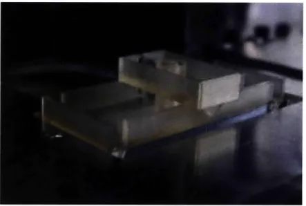
3.2 Fluid Waterfall
The function of this fluid waterfall module is to direct the flow of the slurry and the flow of the wash onto the filter. This is important to both control where the solution falls on the filter as well as minimize the amount of fluid that would possibly drip along the drive system located below. The module is mounted to the rest of the system on the center of the top of the outer box structure. A hollow cylinder has been designed so it can be fastened on the top of the outer box structure (Figures 12-14).
The mother liquor is pumped via a peristaltic pump from a reservoir flask through Tygon tubing and into the Fluid Waterfall module. The end of the tubing is press fit into a hole in the back of the top tier of the module. The mother liquor then cascades through an opening in the front of the module. Two output designs were experimented with to test the drip behavior of the viscous solution onto the filter. The first version has an outlet opening that is identical to the outlet for the ethyl acetate. The opening is 6.35 mm wide, and has protruding triangular "stalactites" in an attempt to direct the flow to a point. Concerns were raised that the mother liquor is initially too viscous, so a second version was created with a rectangular cutout from the bottom of the module as opposed to the side, with a larger triangular stalactite to direct the flow
(shown below in Figure 13 and Figure 14).
--Figure 13 Fluid Waterfall
The ethyl acetate wash goes through a similar flow path, but into the larger lower tier and has 4 different outputs from the module in order for the solution to better spread out across the filter. There are stalactites located at these outputs as well in order to direct the flow as well as prevent the solvent from dripping along the bottom of the module.
Figure 14 Fluid Waterfall Output Alternative
If it decided that this spacing is inappropriately sized, this module can easily be redesigned and refitted with another. It was easy enough to design two testing modules for the mother liquor dripping mechanism. Prototypes for the proof-of-concept were manufactured by 3D printing. Once the proper mechanism is determined, the manufacturability of this piece must be
examined given that it is rather hard to manufacture as one piece using with traditional methods in its current embodiment. In high production, investment casting would be a viable option, as would construction from multiple pieces.
3.3 Metal Filter
The important considerations that were taken in finding the best filter were chemical resistivity, durability, and ease of replacement. Many material options were explored: rolls of cloth, paper discs, ceramic plates, and stainless steel plates. The roll of cloth filter would have been a relatively inexpensive method that would be slowly spooled to provide new cloth in a constant replacement process. This option was eliminated because it would over-complicate the system by necessitating an additional drive system to slowly spool the roll. This system is also a rather high maintenance given that there is the threat of running out of filter material in the middle of the process, so the process must be closely watched and frequently maintained. The paper filter option was eliminated because it was too fragile could not withstand the wear of mechanical scraping. The ceramic filter is the next best option, and offers the same benefits of the stainless steel filter in that they both have a long lifetime and do not need to be frequently replaced. The reason the stainless steel was chosen over the ceramic is because ceramics have a tendency to expand when constantly exposed to fluids and ceramics is comparably more brittle and easy to break than steel.
The stainless steel filter is a porous sintered metal manufactured by Mott Corp. Due to the porous nature of the material, the filter functions omnidirectionally. No matter the filter orientation, capillary action pulls beads of liquid through the filter; gravitational pull on the fluid is not the primary mode of filtration. The filter also machines like a solid steel plate despite its porosity and it was cut into the desired shape (as described in Figure 15 and Section 2.5.6) using an OMAX waterjet cutter. As shown in Figure 15, the mother liquor is designed to fall at the 0 and the ethyl acetate wash at the X's. The blade then sweeps the material back and forth and the resulting wet cake falls into the large cutout spaces.
Figure 15 Metal Filter - Mother liquor falls at the '0'; Ethyl acetate will fall on the X's;
Wet cake will fall through rectangular cutouts.
A filter was chosen to have 5pm porosity (Figure 16), which is large enough to filter the SPP100 molecules and rid the dissolved contaminants and ethyl acetate. This filter utilizes both capillary action to pull the solution into the filter as well as an external vacuum pull to displace the liquid. Looking at the filter before and after an application of mother liquor, it can be noted that there was no difference between the two images, implying that no particles penetrated into the filter itself (Figure 16). This shows that the filter has a long lifetime considering none of the channels are actually plugged. Although the initial fixed cost of purchasing a stainless filter is more than disposable filters, it will pay back for itself in the long run given that replacement parts will not have to be purchased as frequently as if a filter cloth were used and it will reduce the overall downtime of the system.
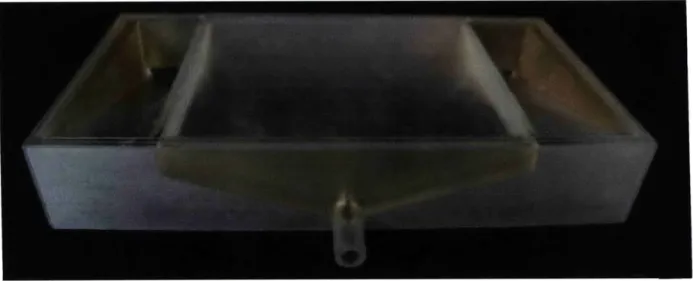
3.4 Fluid Containment
The fluid containment to capture the product and waste was structured accordingly with the input and output locations (Section 2.5.5). All three sections are ramped in order to ensure that all fluids exit the module. This allows the system to be continuous given that there is no accumulation and this module can never reach its capacity. Thus, the filtration unit does not have to be stopped to replace or empty the part.
Figure 17 Fluid Containment Module
The larger section in the middle is under which most of the filtration occurs, meaning the bulk solvent and dissolved contaminants will be funneled through. The liquid is displaced via a vacuum pump through the hollow cylindrical extrusion (Figure 17), into an external waste reservoir. This external waste collection system allows for more modularity given that the waste reservoir is easily replaced and is size adjustable depending on the expected processing
capabilities of the system.
The smaller side sections are where the desired SPP100 molecules falls. The API will slide down the ramp to be funneled into a collector in the rear of the module (Figure 18 and Figure 19).
Figure 18 Top View of Fluid Containment Module
Figure 19 Detail of Fluid Containment SPP 100 Outlet and Compatibility with Outer Structural Box
This module was 3D printed in Transparent FullCure 720, an Objet resin, and then coated with a layer of Fine-L-KoteT M to make it chemically resistive. Three different methods were
experimented with to combine this module with the metal filter. First was a method recommended by an Objet representative; he suggested mixing Loctite 4471 with crumbled cured printer support material because it would bond well to the 3D printed structure. Even if the support material were crumbled finely, this mixture was not of the correct uniformity or viscosity, and resulted in rather thick joints. From experimenting with this mixture, it can be noted that Loctite 4471 is easily absorbed into the filter and leaves behind an unwanted residue. Therefore, a fast drying cyanoacrylate adhesive was applied to the filter to form a non-porous surface that the Loctite could bond to. A bead of Loctite around the rim of the Fluid Containment Module provided a seal with the filter.
3.5 Drive System
A squeegee blade runs along the top of the metal filter in order to move the material over the filter. This blade is fastened onto a delrin spacer, mounting plate, and linear guide block, as shown below in Figure 20. This linear guide block is in turn driven by a Syncromech cable, two Synchromesh pulleys, and a stepper motor.
Figure 20 Drive System
3.5.1 Blade
The blade is the main interface between the pharmaceutical material and ensuring success of the filtration process. The blade angle and material are important in dictating how the mother
liquor and ethyl acetate wash travel across the filter. If the angle between the blade and the filter is too small, or if there is poor contact between the two, the material would be pressed into the filter's pores. This may result in improper filtration and possibly even clog the filter, decreasing potential output. On the other extreme, the blade can accumulate material along the side, yielding poor and non-uniform filtration.
From close examination of the metal filter as well as the performance of the rotary system, it can be noted that the filter is not perfectly flat, but contains bumps and contours that can accumulate material. The stiff metal blades used in the rotary system left much material remaining in the troughs on the filter surface. Therefore, in the linear system prototype, a compliant blade under sufficient preload is used to compensate for the surface inconsistencies.
In addition, the metal-on-metal contact scrapes and scratches the filter-damaging the filter and leaving metal contaminants in the slurry. Chemical compatibility of rubbers with ethyl acetate must be carefully taken into consideration. For example, natural rubber is not recommended for long term use with ethyl acetate: it results in softening, loss of strength, and
swelling of the rubber.
The blade currently being use is adapted from the cleat of a food-grade incline conveyor belt (Figure 20). It is a RMV incline blade, with polyester plies impregnated with rubber-modified vinyl. It resists stains, most oils, fats, and grease, and is impervious to steam and water. The cleats are 38.1 mm high. There is also a smooth glossy outer surface to facilitate cleaning. In addition, they are easy to clean and will not harbor bacteria. Given that there is impregnated rubber in this blade, a more permanent solution must be found in the future. A distinct possibility for the next design iteration is a blade made of silicone. The current blade is rated for continuous use, but this may also slightly corrode or discolor.
Different blade options were hand-tested to experiment with the compatibility of the blade, filter, and mother liquor. To observe this, a preload force was applied by hand onto different blades-metal blades, timing belt, and rubber cleat. The force was relatively consistent throughout the test for all specimens and the best was chosen for our current design.
Figure 21 Detailed View of Linear Guide Assembly
3.5.2 Linear Guide Block
An estimated 22.25 N force is necessary between the blade and the filter to obtain the desired hydraulic seal effect. This translates to 22.25 N acting perpendicularly on the linear guide assembly. A linear guide block with ball bearings (Figure 21) was chosen because its rigidity offers a better load carrying capacity and a better ability to handle off-centered loads as compared to a lead screw or a linear ball bearing design. The guide block with through holes was also chosen over ones with threaded holes to expand the range of possibilities for what to mount. In addition, the through-holes are located marginally farther apart, which would provide more stability under moment loads from the scraping motion of the blades.
A larger mounting plate is attached to the linear guide block to interface the surface with the scraping blade. Four holes were drilled towards the edges in order to attach the blade with the rest of the assembly. These holes were made the same size as the existing holes in order to keep a consistent bolt size. This plate gives us a fairly flexible base on which to mount various blades of different heights and materials to experiment with the best blade shape, material, and force necessary. To adjust the amount of preload between the blade and the filter, fine height adjustments can be made using a delrin spacer plate.
Along the center of the mounting plate and spacer are two holes at each end to attach the eyelets of the Synchromesh cable. These holes were kept in line with the linear guide rail to center the loads and decrease possible moments on the linear guide block.
3.5.3 Linear Guide Rail and Spacer
A bottom mount linear guide rail was chosen so it could be mounted to the ceiling of outer box structure. An acrylic spacer was placed between the linear guide rail and the outer box structure as a means of coarse height adjustment between the linear guide assembly and the filter (Figure 22). Initially, the idea was to have standoffs at each bolt hole's location; however, it is difficult to machine standoffs that are all the same exact length while not over constraining the rail. Using a solid piece of material gives the assembly the large surface to press upon as well as provide the appropriate spacing for blade height. This distance was carefully engineered to be as
large as possible without having the linear guide rail interfere with the other modules.
Figure 22 Linear Guide Assembly
3.5.4 Synchromesh Drive
To drive the linear guide block along the rail, a stepper motor combined with Synchromesh pulleys and cables were used. The cable has a secondary helical winding, which conforms to notches within the pulley to ensure that the line does not slip as an O-ring might
under wet and slippery conditions (Figure 23). Given that the motor position is rather critical in this unit to provide the sweeping blade motion, it was important to have a drive chain that would not slip and on which the stepper motor could reliably count steps. The radius of the pulleys were carefully engineered to ensure a reasonable motor torque, that the cables did not interfere with the fluid waterfall, and that it would pull the linear guide block from the center of stiffness to reduce moments.
Figure 23 Capstan Drive Pulley and Synchromesh Close-Up View
3.5.5 Pulley Mount
Looking at the unit as shown in Figure 11, the pulley mount (Figure 24 and 25) is located on the left. The pulley is mounted with a set screw onto a flat of a 9.5 mm diameter steel shaft. The shaft is axially constrained from falling by an e-clip on top of the pulley mount and is radially constrained with two flanged double sealed ball bearings. The bearings are press fit into a 6.35 mm thick 50.8 x 101.6 x 101.6 mm aluminum extruded hollow rectangle. Recesses were drilled for the bearing flanges to remain flat and concentric when press fit. The 50.8" aluminum extrusion height was chosen with St. Venant's principle in mind. The shaft diameter was set by the inner diameter of the pulleys, hence using St. Venant's theorem of proper constraint being
3-5 times the characteristic dimension (in this case the diameter of 9.3-5mm), this ranges for a height
of 28.57 mm to 47.62 mm Considering the thickness of the walls are 6.35 mm thick, the pulley mount falls within these requirements.
Figure 24 Pulley Mount
Two parallel slots were machined on the bottom of the pulley mount to fasten it to the outer structural box and allow for cable tensioning. Matching slots are machined into the outer structural box to allow for a greater range of motion and the left slot is centered to the linear guide rail. If more tension is needed, the pulley mounts can be slid further apart and secured with bolts, as shown in Figure 25.
Figure 25 Slots in Pulley Mount and Outer Box Structure for Cable Tensioning
3.5.6 Motor Mount
The motor mount is located on the other side of the pulley mount and is responsible for driving the entire system (Figure 26). It is similar to the pulley mount given that method of attaching the shaft is similar, with a flat on the shaft and a set screw (Figure 27). In addition there are similar slot features on the motor mount to fasten it onto the outer structural box. The motor mount is designed to be larger than the motor pulley unit to allow the pulley itself to hang lower, decreasing possible deflections in addition to providing space to couple the pulley shaft to the motor shaft. As such, the pulley unit for the motor is smaller and is mounted to the rest of the motor assembly with four bolts. The motor shaft and pulley shaft are concentrically aligned and attached using a coupling to account for any additional misalignments and to translate motor rotation to the shaft.
Figure 27 Motor Mount - Bottom View
Another reason the motor is located externally from the rest of the process is due to safety concerns. Ethyl acetate is highly flammable, so possibilities of shorts or sparks must be minimized.
3.5.7 Motor
Basic assumptions taken while sizing the motor was that the preload of the blade against the filter would result in a 5lb-force or the equivalent of about 22.25 N. A safety factor of 2 was used to account for any variations or changes in blade. It was rather difficult determining the necessary coefficient of friction to be used considering the metal filter is of porous steel as opposed to a smooth finish and there was a wide range of possible friction coefficients, from 0.6 to 4. One would expect a porous material to have a higher coefficient of friction considering it is a bumpier and non-smooth surface, so the largest coefficient of friction found was chosen as
an additional safety factor. Thus, the force of friction seen by the blade on the filter is
Ffr = MN (2)
The diameter of the pulley is based on the dimensions and spacing between the linear guide and the side wall of the outer structural box to prevent the fluids from dripping onto the cable. From this information, the necessary motor torque was calculated by:
T = FfrR (3)
These numbers and equations were put into an excel spreadsheet to allow for quick value adjustments (Table 1).
Table 1 Motor Sizing
English Metric
Safety Factor S 2
Normal Force of Blade on Filter (expected) Ne 5 lbs 22.24 N
Normal Force of Blade on Filter (with safety) N 10 lbs 44.48 N
Coefficient of Friction (Rubber+Steel) U 4
Friction Force of Blade Ffr 177.93 N
Diameter of Pulley D 0.03 M
Radius of Pulley R 0.02 M
Motor Torque T 2.70 N-m
From this information, stepper motor model 8718S-OlSv from Lin Engineering was chosen given that it was one of the highest output torque motors available, especially given that we are running at a rather low speed for a motor. The motor is connected in series given that we are operating at relatively low speeds (Figure 28). The highest rated torque for the motor is about 2.35 N-m, but given our extravagant safety numbers, this small differential is negligible.
WO-8718S-01 48 vDC, 1.4 Amps/ Phase, Bipolar Series, 1/2 Stepping
WO-87ISS-01 48 VDC, 2.8 Amps/ Phase, Parallel Series, 1 2 Stepping
350, -2.50 2,00 150 100 0.50 0 1000 2000 3000 4000 5000 *sdps PI O s0-91 iL OAl 6000 7000
Figure 28 Motor Torque-Speed Curve
This motor unit is driven by the Lin Engineering Driver and Controller model R356, which comes with an optical homing sensor to allow for the motor to return "home" consistently as well as a USB KIT to easily connect it to the computer. A small red flag was secured to the Synchromesh cable to enable the homing switch. (Figure 23). The motor is rated to run up to 48V, yet the driver is programmed to run on a maximum of 40V. This does not really matter considering the motor torque is based off the current through the motor, which is automatically set to have a 10% holding current and a 30% running current of the maximum of 3 amps, which is enough for our application.
3.6 Outer Box Structure
The outer box structure originates from a foot long piece of 152.4 x 152.4 mm hollow rectangular aluminum extrusion (Figure 29). A side was machined off for the placement of a viewing window (Figure 31).
At the top, there are slits for flexible adjustment of the motor mount and pulley mount, as described in Sections 3.5.5 and 3.5.6. In addition, in the center of the top, there is space for the fluid waterfall. At the back, there are 2 slits for the fluid containment system to deposit the wet cake. On the bottom, 4 feet were drilled into the bottom so it can be height adjusted to remain flat on whatever surfaces it will ultimately be placed and to damp any possible vibrations (Figure 30).
Figure 30 Outer Box Structure - Bottom View
Note: Lovely machining done by Central Machine Shop
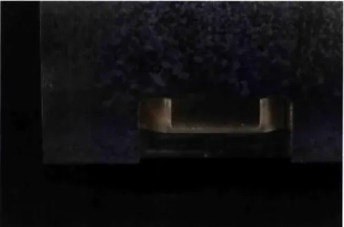
3.7 Viewing Window
The viewing window is made of polycarbonate and provides both a wall to contain the process and as well as a window for the viewer to safely observe the process (Figure 31). The hole is located in the middle for the waste outlet from the fluid containment module.
U
p
e
There are also grooves machined into the top and bottom so it fits snuggly with the outer box structure. In addition, the top and bottom is lined with socket cap screws to keep it in place. There are also notches machined in the top and bottom to make sure it fits snuggly with the outer box structure (Figure 32).
Figure 32 Detail of Interface between Viewing Window Notch and Outer Box Structure
CHAPTER
4
RESULTS
The linear filtration unit was tested in its entirety at room temperature in a fume hood due to the vapors caused by the large amount of ethyl acetate (Figure 33). The machine itself occupied approximately 0.03 cubic meters within the fume hood, less than the targeted 0.23 cubic meters. Initially, getting the machine to start up was a bit tricky considering the large amount of friction between the blade and the filter in addition to the small unexpected behaviors of a system when it was first run. Once steady state had been reached, it performed fairly smoothly. In initial dry runs, the middle of the blade had a tendency to get stuck on the return while it was over the output outlet. Again, under steady state, this no longer posed as an issue.
Initially, when the mother liquor was pumped into the system, it had started to accumulate at the input of the fluid waterfall module rather than flow to the edges of the tray. Wetting the tray eliminated this issue, and the risk of overflowing. Both fluid waterfall concepts were also tested in this run-through and both encountered a similar issue: output fluids did not drip freely from the top tier, instead running along the underside of the top tier and onto the outside of the lower tier. By dripping down the side, the fluids inevitably dripped down the side of the linear guide
assembly and much of the fluids fell onto the mounting plate of the linear guide assembly.
This occurred because the output of the top tier was too close to the outer wall of the lower tier. In this case, the first version of the upper tier stalactites was more effective in controlling and directing the flow because the output gap was smaller and resulted in a thinner flow to the stalactite. More stalactite options will have to be tested in order to get the best and most efficient flow and prevent ethyl acetate from flowing onto the linear guide. Additionally, another safety precaution to prevent damage to the linear guide would be to add protective bellows in order to prevent contaminants from seeping into the assembly.
Aside from those minor and easily adjustable concerns, the overall flow of the system worked. There was a good balance for fluid flow given that there was only 1 output for the mother liquor to fall and 4 for the ethyl acetate. This allowed the mother liquor to accumulate and spread in one spot whereas the wash could spread to provide better coverage for the material translation.
The blade had worked well and did not push the API into the filter, but rather acted much like a squeegee and had a good balance of pushing waste liquid into the filter and wet cake across the surface. In Figure 34, one can see that when the blade is on one end, the mother liquor falls to the center and is given a chance to filter through before it is pushed over and washed in the pure ethyl acetate. This initial filtration is important in the washing process, so the timing of the blade motion before moving into the mother liquor and into the ethyl acetate is effective. After pushing the API into the wash, a thick layer of the material is gathered on the blade (Figure 35) and deposited into the output hole when the blade scrapes over the middle of the hole (Figure 36). The decrease in friction and the fact that the ends of the blade were still on the filter, allows the blade to smoothly return.
Figure 34 Scraping over Accumulated Mother liquor Pool
Figure 35 Scraper Blade and API Filtration
Figure 36 Accumulated Output from Blade
It is hard to know exactly how the outputs in the fluid containment system should be structured given that the desired consistency of the material is highly variable. It is known that under refrigeration, the material is much less viscous than the current outputted cake given that none of the ethyl acetate would be able to evaporate. In either case, the output hole should be a big bigger to account for higher yield. At the moment in its dry state, the material does not flow down the ramp and just accumulates in the output ports (Figure 36), but under refrigerated conditions, there should be a better flow. If gravity feed is still not sufficient a powered system, e.g. a vacuum conveyor, could be implemented.
CHAPTER
5
CONCLUSION
As a proof of concept prototype, this filtration module fulfills its goal and shows that a small-scale continuous linear motion filtration unit is possible. This unit is part of a larger goal presented by Novartis, to convert pharmaceutical production from a large-scale batch process to a small-scale linear process. Success would yield increased flexibility in pharmaceutical manufacturing, allowing small-scale production of drugs that are not financially sensible to be made in large quantities. This would lower the costs for the company as well as produce more specialized drugs-drugs with fewer side-effects or target those with less common ailments. With some refinement-more detailed process parameters, elegant refrigeration implementation, and integration with both upstream and downstream processes-we would have an efficient working section of the drug manufacturing process.
In the author's opinion, the most innovate design elements are the use of (1) a porous metal filter and (2) a compliant blade. The metal filter is easily machined, unlike ceramic filters, and is robust, resulting in a longer lifetime, less maintenance, and reduced costs. In addition, the use of a compliant blade is a necessity in efficient filtration of the system, and a substantial improvement over metal blade designs. The compliancy compensates for inconsistencies in the filter as well as acts as a squeegee so no material is left behind.
Compared to the rotary model, the linear system facilitates experimentation much more given that each component is easily detachable and there is only one working blade as opposed to four. Having one blade also ensures consistency within the filtration process. In the rotary system, four blades must be changed each time an experiment is run, and the blades are mounted in such a way that replacing them is time intensive. The architecture of the linear system, however, simplifies the process by having a single blade and shim to set the blade preload.
Lastly, a linear filtration unit will likely scale better than a rotary system. The most efficient way of expanding the process is not to purely increase the input flow, but to increase the width of the unit in addition to length and the number of outputs in the fluid waterfall module so there is more fluid flowing onto the filter. A pure increase in input flow would be more efficient to a
certain point before the filtration capacity of the filter is reached and the mother liquor just accumulates and will not properly filter. An increase in the length of the system combined with an increased flow rate would also not be the most efficient method considering the initial exposed surface of the mother liquor is still meant for the smaller flow rate, and the initial filtration step would be less efficient. The best way to increase the production is to add another output for the mother liquor in the fluid waterfall, so there is a uniform and relatively thin amount of API spread across the surface to allow for better filtration.
5.1 Future Work
Aspects of this unit that must be addressed in future work include the concept refinement ideas generated in the Results and Conclusion. In addition, we must consider the traditional manufacturability of the parts that were prototyped by 3D printing, the compatibility of the filtration unit with the downstream heating and drying units, an elegant method of incorporating refrigeration, detailed specifications of process parameters, the addition of sensors, and general refinement to reduce cost, size, and waste.
The process parameters for the API must be defined and experimented with in order to achieve the best output that is the most compatible with the downstream drying unit. These parameters include blade shape, material, speed, force, and angle to filter. In addition, the spacing between the input of the mother liquor, ethyl acetate wash, and output must be optimized for the process.
5.2 Things Learned
This section mainly focuses on the logistics in completing an undergraduate senior thesis under Professor Martin Culpepper. I had learned a lot this year-the design and fabrication of a
system I can call my own has given me much confidence in applying the knowledge I have gained from my four years here. To get to this point, I have run into many speed bumps (you can only imagine) and challenges putting me in a situation to grow technically and personally. This is the survival guide.
Persistence and hard work is key and high performance standards in design and execution are critical. The most important initial step once a design has been chosen is a detailed part list.
This enables the creation of a GANNT chart to stay on schedule and facilitates the organization of ordering parts, machining, and assembly.
When something does not go as planned or fails to work (e.g. motor problems), do not panic! Take a deep breath, a step back and think of all possible plans of action. Otherwise, get a good night's rest and attack the problem in the morning, once refreshed. There may be times where one is working until midnight and Professor Culpepper is still there. Do not be intimidated. In this case, go on a La Verde's run and bring him a bottle of Diet Coke for energy-he will really appreciate it! Also, beware of excessive carbohydrate consumption because it can lead to diabetes.
It is also ok to make mistakes-Professor Culpepper will refrain from taking out the chainsaw if it is a learning opportunity. For example, I have learned that linear guide blocks are fragile and it is important to have a stopper at the end of a linear guide rail to prevent the bearing from sliding off and falling to its doom. If one attempts to reattach the linear guide block to the rail and notices ball bearings falling out: stop, collect balls, open the bearing, and replace the ball bearings. Despite what some may tell you, not all the ball bearings must be retrieved from the floor (especially if they are about 3mm in diameter and hard to find). It is possible to buy replacement ball bearings as opposed to a whole new linear guide. This option is vastly cheaper and the bearing block is an interesting mechanism, so one will learn a lot from taking it apart. Check the ball bearing diameter and ask Bill in LMP if he has any hidden away. In this case, he will be more inclined to help if one is friendly and smiles on a normal basis, especially if he is about to go home. Linear guide blocks do not need all of the ball bearings to function properly. Although it is not recommended, the guide blocks can properly function with a significant number of ball bearings missing.
If any questions arise during the design phase or during the use of a machine, it is always better to ask and double check in a way that shows one has thought about it. This is especially true with design consultations. In the machine shop, this option is much safer and will yield in higher quality parts considering the shop guys have accumulated many tricks over the years. Go early in the morning so they are rejuvenated and have not yet been worn down by students in 2.007 or 2.008. Also, despite popular belief, donuts are not the preferred snack of choice for shop guys; they prefer healthier and more savory options, such as donuts. If in doubt, black coffee is always a safe option.
Confidence is critical, especially when working with a client, people of strong personalities, or in interdisciplinary teams. Everybody will have their own idea of what should happen, but nobody knows the system as well as the designer, so trust your judgment because it is ultimately your machine and you are responsible! It is also important to fully understand client needs and decipher what this means, work-wise. The client and technical Mechanical Engineers speak different languages; the client will often have an idea of how something should work, will want many different things at once, and quickly change specifications without warning. Don't get distracted: break down their requests, take it one step at a time, and accomplish the fundamental goal that will allow for everything else to fall in place.
Other useful information is that it is important to check the Objet printing materials and make sure that it only prints in the selected material (not similar materials)-if there is any "tango" material, the part will come out squishy. It is also useful to scrape off the bulk of the support material before using the waterjet to clean 3D printed parts. Otherwise, the probability of the waterjet flooding is significantly increased. If a mop is ever needed, there is one located by the entrance of LMP near the OMAX waterjet.
Lastly, be careful when working with chemicals. Methanol is known to cause blindness and paralysis, so avoid skin contact or consumption. Ethyl Acetate also slightly reacts to polycarbonate. If one needs a chemical to clean a surface and water is not sufficient, use a mixture of 70% Ethanol and 30% water.
REFERENCES
[1] Personal conversation with Rohit Ramachandran, Post Doctorate Associate, Sept 30, 2009 [2] Personal conversation with James Evans, Research Associate, April 26, 2010
[3] http://www.filtraguide.com/en/360/ext/104603/andreas
![Figure 3 Existing Batch Filtration Modules [3]](https://thumb-eu.123doks.com/thumbv2/123doknet/14685391.560128/14.918.113.740.120.392/figure-existing-batch-filtration-modules.webp)