DPF: A Dynamic High-Performance Network Packet Filter
by
Dominic Sartorio
Submitted to the Department of Electrical Engineering and Computer Science
in partial fulfillment of the requirements for the degrees of
Bachelor of Science in Computer Science and Engineering
and
Master of Engineering in Electrical Engineering and Computer Science
at the
MASSACHUSETTS INSTITUTE OF TECHNOLOGY
May 1995
( Dominic Sartorio, MCMXCV. All rights reserved.
The author hereby grants
paper and electronic copies
/
IA
to MIT permission to reproduce and distribute publicly
of this thesis document in whole or in part, and to grant
others the right to do so.
-
//
Author
...
Department of "lectrical Engineering and Computer Science
j/ May 12, 1995
/1
f //I
/Certified by ...
.. \Accepted by ...
Chairman, Depar
A .,J ...
...
/y
. Frans Kaashoek
Assistant Professor
Thesis Supervisor
£(1
l .. Ala
... .... .I
F
I
t..
4... ... ....
Frtment Commit
Morgenthaler
:tment Committeon !raduate Theses
IMqASSACHUSETTS INSl I TUTE OF TECHNOLOGY
AUG 101995 LIBRARIES
I-I I
DPF: A Dynamic High-Performance Network Packet Filter
by
Dominic Sartorio
Submitted to the Department of Electrical Engineering and Computer Science on May 12, 1995, in partial fulfillment of the
requirements for the degrees of
Bachelor of Science in Computer Science and Engineering and
Master of Engineering in Electrical Engineering and Computer Science
Abstract
Using packet filters, a network application can describe which incoming messages should be
delivered to that application. Applications submit packet filters to a packet demultiplexor,
which uses them to direct messages to the correct applications. Most current packet filters are written in low-level imperative languages, which are then interpreted in turn by the demultiplexor on each incoming packet. This framework can be very inefficient for two main reasons. First, the interpretation of low-level imperative code is inherently slow. Second, most demultiplexors today do not adequately recognize and exploit similarities between filters.
In this thesis, we describe the design and implementation of the Dynamic Packet Filter (DPF), a novel packet filtering system that significantly improves demultiplexing
perfor-mance. DPF incorporates three ideas that contribute to fast demultiplexing. First, filters
are written in a higher-level declarative language, allowing for more efficient recognition and exploitation of overlap between filters. Second, filters are merged such that no instruction is run more than once on any given packet. Third, instead of interpretation, dynamic code generation is performed on the merged filters, with the resulting machine code then run on incoming packets. As a result, DPF demultiplexes packets much faster than other existing
demultiplexors. At the cost of a higher setup time, DPF performs at least six times to an order of magnitude faster than Pathfinder and the Mach packet filter, two high-performance packet filters.
Thesis Supervisor: M. Frans Kaashoek
Acknowledgments
I would like to thank the following people, whose help in completing this thesis was invalu-able:
To Frans, for the overall supervision of this project, and for all his help in shaping and writing this thesis. In particular, his careful reading of many drafts and his many helpful comments were invaluable. Finally, I thank him for challenging me to learn as much as I did.
To Dawson, who generated the core ideas behind DPF, including the use of a declarative
language, the merging of filters regardless of where instructions appeared, and the dynamic code generation thereof. He also wrote the parser and provided the groundwork for DCG. Finally, I thank him for his continuous technical supervision. I could not have done this
without him.
To Josh and Anthony, my officemates, for providing input and patiently answering my annoying questions.
To Willy, my roommate, for graciously accepting my complaining. To my parents, for moral support.
To others, who remain unnamed (but you know who you are), for your timely support, advice, suggestions, and constructive criticism. Thank you all very much for your help.
I 1.1
Contents
1 Introduction
1.1 Background ...
1.2 The Problems with Current Packet Filters . 1.3 Our Solution.
1.4 Thesis Overview ...
2 The DPF Language
2.1 Overview ... 2.2 The DPF Language.
2.3 Fragment Recognition and Reassembly .
3 DPF Implementation
3.1 Overview.
3.2 Parsing DPF.
3.2.1 Parser Implementation ...
3.2.2 Parse Trees' Canonical Ordering .... 3.3 Merging Filters ...
3.3.1 Inserting New Filters ... 3.3.2 Removing Inactive Filters ... 3.4 The True-False Tree.
3.5 Disjunctive atoms ...
3.5.1 Filter Insertions and Removals with Disjunctive
3.5.2 Constraints Regarding Disjunctive Atoms . . .
3.5.3 Disjunctive Atoms in the True-False Tree . . . 3.6 Handling filter priorities ...
6 6 8 8 9 10 10 11 14 19 19 21 21 22 24 24 28 30 35 36 37 39 40 . . . . . . . . . . . . . . . . . . . . . . . . . . . . . . . . . . . . Atoms . . . . . . . . . . . . . .
...
...
...
...
...
. . . . . . . . . . . . . . . . . . . . . . . . . . . . . . . . . . . . . . . .3.7 Dynamic Code Generation ... 3.7.1 The Basic DCG Algorithm ... 3.7.2 DCG Optimizations ... 3.7.3 DCG Implementation Details ... 3.8 Summary ...
4 Results of Experimental Evaluation
4.1 Introduction .
...
4.2 Test #1: Time to Accept One Packet ... 4.3 Test #2: Acceptance Time vs Protocol Depth ... 4.4 Test #3: Similar vs. Dissimilar Filters ...
4.4.1 Completely Dissimilar Filters ...
4.4.2 Similar Filters -
Merged by MPF and DPF . . .
4.4.3 Similar Filters - Merged by DPF, Not Merged by
4.5 Test #4: Insertion/Deletion Time ...
4.6 Test #5: Fragment Recognition/Reassembly ...
4.7 Test #6: Priorities ...
4.8 Conclusions ...
5 Discussion
5.1 Performance Considerations.
5.2 The Effects of Dynamic Code Generation ... 5.3 The Effects of Filter Merging ...
5.4 The Effects of a Declarative Language ...
5.5 Improving Fragment Recognition and Reassembly ...
6 Related Work
6.1 CSPF ...
6.2 BPF ...
6.3 MPF...
6.4 PathFinder ...
6.5 Dynamic Code Generation ...
7 Conclusions 41 41 42 42 43 .. . .. . .. . .. . .. . .. .
MPF
.. .. .. 45 45 47 48 49 50 51 52 53 56 56 57 58 58 59 60 60 6163
... .
63
... .
64
... .
65
....
66
... .
67
68
...
...
...
...
...
. . . . . . . . . . . . . . . . . . . . . . . . . . . . . . . . . . . . . . . . . . . . . . . . . . . . . . . . . . . . . . . ....
...
...
...
...
I 1'1
Chapter 1
Introduction
This thesis discusses the design, implementation, and performance of the Dynamic Packet
Filter (DPF), a novel network packet demultiplexor that provides an alternative over other
user-level packet filters through superior demultiplexing performance. DPF accomplishes this by incorporating three main ideas. First, filters are written in a higher-level declarative language instead of an imperative language, allowing for more efficient recognition and exploitation of overlap between filters. Second, filters are merged such that no instruction is run more than once on any given packet. Third, instead of interpreting filters, dynamic code generation is performed on them, with the resulting machine code then run on incoming packets. At the cost of a higher setup time, DPF performs at least six times to an order of magnitude faster than Pathfinder and the Mach packet filter, two high-performance packet filters.
The remainder of this section will provide the background and motivation behind DPF and a brief overview of the remainder of this thesis. We define terminology and then state the problem with existing filtering systems. We then offer our solution, based on our observations regarding the packet filtering problem, and preview the most significant results. Lastly, an outline of the remaining chapters is provided.
1.1
Background
A multiprogrammed computer attached to a network needs a means by which it can decide which application will receive a network packet addressed to that computer. This is the role of the packet demultiplexor. Most often located in the kernel or some trusted server,
it demultiplexes an incoming stream of packets towards their intended applications. To do this, it requires specifications of the packets that the respective applications are interested in. These specifications are known as packet filters because their semantics are such that they filter a packet stream and allow only those packets that meet its specification to be directed towards its application. Alternatively, packet filters can be regarded as boolean functions performed on each packet by the demultiplexor, with "true" indicating that the given packet belongs to that filter's application (accepted), and "false" indicating otherwise
(rejected). Packet filters can either be directly installed as part of the demultiplexor or
provided during run-time by the applications themselves. This latter class of filters, known as user-level filters, is the topic of this thesis.
User-level filters are popular because they provide more flexibility and less maintenance headache than hand-coded implementations of network code. By having applications pro-vide their filters to a protocol- and application-independent demultiplexor during run-time,
one does not need to take the whole system off-line and manually update the
demulti-plexor whenever a new application or protocol needs to be supported [15]. In order to make demultiplexors as general-purpose as possible, filters are written in specialized safe languages and the demultiplexor itself consists of an interpreter that runs incoming packets through the instructions of each filter. These safe languages are usually stack-based [15] or register-based [13, 21] imperative languages, and the interpreter accepts and rejects packets
by running these imperative instructions on them and returning the final boolean value.
Each filter is run against a given packet in turn until one of them accepts it or all reject it. This framework, however, has been too slow on some networks, especially faster modern networks such as ATM [4]. Although some recent work has improved the demultiplexing of user-level filtering systems to somewhat more tolerable levels of performance [4, 21], other recent work suggests that the user-level packet filter model may be inappropriate for fast networks because it is inherently too slow [7, 8]. This thesis proposes a packet filtering system that achieves the flexibility and maintainability of user-level packet filters, while significantly improving demultiplexing performance.
1.2 The Problems with Current Packet Filters
Three observations regarding the nature of packet filtering indicate where there is room for improvement in demultiplexing performance. First, many filters exhibit a good deal of overlap. They share many common instructions, mostly because they may look for packets of the same protocol. Others may differ by only a few constants. However, most demultiplexors today do not adequately take advantage of this overlap. The result is many
redundant computations, contributing to poor demultiplexing performance. It should be
possible to merge filters or otherwise recognize common computations. Merging filters
results in fewer filters that must be run in turn through the interpreter, thus resulting
in improved demultiplexing performance. Some more modern demultiplexors [4, 21] do this to some extent, but there is still much room for improvement. For example, modern demultiplexors merge filters if their first few instructions are identical, but do nothing to recognize identical instructions appearing after different instructions.
Second, the imperative languages in which most modern filters are written have seman-tics that lend themselves to inefficient interpretation [13, 15, 21]. In particular, they do not capture very well the notion of a packet filter being a boolean function on packets. We believe that imperative languages provide a too low-level semantics for the packet filter, and result in both inefficient interpretation and inefficient merging of filters.
Third, interpretation itself is slow. An interpreting demultiplexor with even just one active filter may not keep up with the maximum bandwidth on an ATM [4].
1.3 Our Solution
Based on these three observations of how to improve the performance of packet filters, we have designed and implemented DPF, the Dynamic Packet Filter system. DPF is based on three ideas. First, DPF performs more aggressive merging of filters that exhibit similarity. DPF recognizes common instructions regardless of location within a filter, and ensures that no instruction is executed more than once on a particular packet. This is a significant improvement over all other existing demultiplexors, in which the recognition of common instructions is location-dependent.
Second, DPF's filter language is a higher-level declarative language whose semantics more closely match the concept of a packet filter as a boolean function. A declarative
language allows filters to be easily written in a form that more closely matches the packet
specifications they are intended to describe, without describing the imperative instructions
that a machine should execute [4]. This allows a more efficient implementation of DPF's merging of common filters. Pathfinder [4], a recent packet filter system, also uses a declar-ative language, but does not exploit it fully for merging similar filters.
Third, DPF does not interpret filters. Instead, dynamic code generation is performed on
filters upon their insertion and removal, and the resulting machine code is run on incoming
packets. Since running machine code is inherently faster than interpretation, this results in
much faster demultiplexing of packets. Dynamic code generation of packet filters has been suggested in previous work [9, 15, 20], but no filter systems have used it, to our knowledge. We have implemented and tested DPF. Our implementation runs in user-space and tests were run by reading filters from UNIX files and applying them to sample packets of common networking protocols. Results were compared to the Mach packet filter (MPF) and Pathfinder, two recent high-performance packet filter systems. We have shown that
DPF performs significantly better than both of these, demultiplexing at least an
order-of-magnitude faster than MPF and at least six times faster than Pathfinder in most cases.
This improved demultiplexing performance comes at a cost - namely, the setup cost in-volved when filters are inserted and removed from the DPF system. Because DPF performs aggressive filter merging and dynamic code generation, which other filter systems do not perform, DPF requires more cycles during insertions and removals. However, we consider trading setup time for faster demultiplexing to be an acceptable tradeoff, mostly because we expect that setup operations happen infrequently on most systems.
1.4 Thesis Overview
The remainder of this thesis describes the background, design, implementation, testing and
analysis of DPF, and is divided as follows. The next chapter describes the DPF language. Chapter 3 details DPF's filter-merging algorithms and dynamic code generation. Chapter
4 describes the test suite and results, and provides some analysis of those results. Chapter
5 analyzes DPF's results in some more detail by discussing how resolving each of our three
observations contributed to DPF's performance. Chapter 6 discusses related work. Chapter
I I! I
Chapter 2
The DPF Language
2.1
Overview
The DPF language consists of a simple declarative instruction set. This instruction set
is declarative because it is used to provide a specification of the values found in specific
bitfields in an incoming packet in order for that packet to be accepted, without describing procedurally how a machine should go about demultiplexing that packet. A broad range of simple operations are supported, thus allowing DPF to handle a broad range of possible protocols. Fragmentation of packets is also supported.
The DPF language captures the notion of a packet filter being a conjunctive set of boolean operations on a packet's header. We call these boolean operations atoms and a conjunctive sequence thereof predicates. Predicates are intended to be complete specifica-tions of packets, but sometimes this is difficult to do in a single conjunctive sequence. A complete filter, then, is a disjunctive sequence of one or more predicates. The whole filter is intended to return a boolean when checked against any given packet, indicating whether this packet is accepted or rejected by the filter.
The language also incorporates the semantics of fragment recognition and reassembly by allowing for two special kinds of predicates. First, one can write specifications of packets that should be postponed for later demultiplexing (in the form of postpone predicates). These predicates are intended for out-of-order fragments that arrive before the first one, which contains the header information required for demultiplexing. Second, one can write specifications of fragments arriving after the first one arrives (called subsequent fragment
can easily identify fragments of a given packet. DPF provides a means for doing this by allowing one to write predicates that include a check for the message ID found in the first
fragment.
The remainder of this chapter describes the DPF language in more detail. Section 2.2 describes the grammar, and section 2.3 expands on how the DPF language can be used to express fragment recognition and reassembly.
2.2 The DPF Language
The grammar of the DPF language is given in Figure 2-1. For readability and easy im-plementation of packet filters by the application writer, familiar C syntax is used wherever possible. The grammar and syntax are more fully explained in the following paragraphs.
An atom describes a boolean operation which the packet filter is intended to perform
on a field of the packet. Its intended basic syntax, (bitfield reLop constant), captures these
semantics. The grammar indicates and our implementation supports the possibility of more
complicated formulations of atoms. Any number of functions on any number of bitfields and constants can appear on either side of the rel-op. In practice, we have found that only
the formulation (bitfield reLop constant) is really needed.
Any of the six basic relational operators and many different arithmetic operators can
exist within an atom. While many of these operations will not be needed for most protocols,
they are included for added programming flexibility. Furthermore, they are easy to support.
In fact, our experience leads us to expect only two relational operators, "="
and "!=", to
be in common use. Likewise, for arithmetic operations, we have found "+", "&", and the shift operators to be sufficient for most modern protocols.
Bitfields, values to be extracted from the specified bits in the packet, are represented by a factor and a constant seperated by a colon. The left factor must represent the offset in
bytes of the base of the bitfield from the beginning of the packet. The right constant must
represent the length of the bitfield in bits. Currently, only 4, 8, 16 and 32 are legal bitfield sizes.
The predicate is intended to represent a complete specification of the desired packet, consisting of a conjunctive set of boolean operations. Syntactically, it consists of a set of atoms joined by "&&" operators. Logically, the atoms are checked one at a time. If one is
filter: '(' predicates ')' '{' predicates '}' ]?
IE
predicates: predicate
I predicates '11' predicate
predicate: atom
I predicate '&&' atom
atom: factor rel_op factor
I '(' factor rel_op factor ')'
factor: term
[sign]? factor
I factor arith_op factor
I '(' factor ')'
term: constant
I bitfield
bitfield: factor ':' constant
constant: ['0'-'9']? /* decimal */ I 'Ox'['O'-'f'] /* hex */ I 'bx'['O'-'i'] /* binary */ I '0'['0'-'7'] /* octal */ sign: '+' I '-' relop: '<' '<= ' '>' '>= ' ' = = ' '!= '
arithop: '+' I '-' I '*'I '' I '.' I 'A' I
I '&' I '<<' I '>>'
Figure 2-1: Grammar for the DPF language. I 1.1
( /* Ethernet header */
((2:16) == Ox0200) && /* Check if a PUP packet */
/* PUP header
((7:8) > 0) && /* Check if O<PupType<=100 */
((7:8) <= 100) &&
((14:32) == 123456) && /* Check destination socket */
((19:8) == 12) && /* Check source host ((20:32) == 123456) /* Check source socket
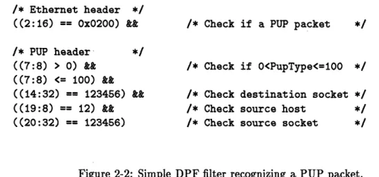
Figure 2-2: Simple DPF filter recognizing a PUP packet.
false, then the packet is immediately rejected by that predicate. All atoms must be true for the packet to be accepted by that predicate.
Figure 2-2 gives a simple example of a DPF packet filter. This filter accepts PUP packets [5] of a specified range of types arriving via an Ethernet from a specified socket and address, and being sent to a specified socket. The first atom verifies that the packet is a PUP packet by checking the appropriate bitfield in the Ethernet header. Whether it is within a given range of PupTypes is determined by the next two atoms, representing the two inequalities necessary to verify this condition. The next three atoms are simple equalities checking the source and destination of this packet.
Normally, an application's filter will consist of just one predicate, but occasionally an application may be interested in a set of packets that cannot be specified by one conjunctive set of booleans. Thus, filters consist of one or more predicates joined by "11" operators. If
at least one predicate's atoms are all true, then the packet is accepted. If no predicate's
atoms are all true, then the packet is rejected.
DPF supports indirect loads, in which the left argument to the ":" (bitfield) operator
can itself be a function of other bitfields. This situation often arises in practice when one wishes to check a bitfield in a protocol header that appears after the variable-length header of a lower-level protocol. The Internet protocol [1] is a prime example. IP itself consists of a header which is variable in length due to the possible presence of some optional fields. Its header also includes a bitfield indicating the length (in 32-bit words) of the header. Thus, in order to check bitfields of higher-level protocols (such as TCP [2] and UDP [16]), one must find the header length in the IP header. DPF simplifies this process by allowing the packet
/* Ethernet header */
(2:16 == Ox0800) && /* Check if IP datagram */
/* IP header */
((10:16 & Oxbfff) == 0) && /* Check if unfragmented */
(13:8 == 6) && /* protocol == 6 indicates TCP */ (16:32 == OxcOOc4501) && /* Check source IP address */
/* TCP header */
( (((4:8 & Oxf) << 2) + 4) : 16 == 1234) && /* Source port */ ( (((4:8 & Oxf) << 2) + 6) : 16 == 4321) /* Destination port */
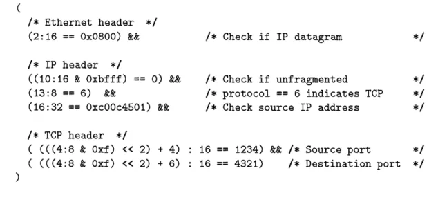
Figure 2-3: Sample DPF filter recognizing a TCP/IP packet.
filter writer to write the base offset of a bitfield as a function of these header-length bitfields. Figure 2-3 provides the case of TCP/IP as an example. The last four bits of the bitfield (4:8) contain the length of the IP header and must be used in defining bitfields in the TCP header, such as (in this example) the packet's source and destination port numbers. Here, we extract the relevant four bits by masking (4:8) with Oxf, left-shift the result twice to
obtain the IP header length in bytes, and then add a constant to account for the Ethernet
header's length and the location of the port numbers within the TCP header.
2.3 Fragment Recognition and Reassembly
The DPF language also supports packet fragment recognition and reassembly. Since most networks have a maximum message size, protocols (including the IP protocol [1]) break packets into multiple fragments. The task of reassembling these fragments usually falls on their recipient. As an additional complication, these fragments may appear out of order. DPF provides a facility for detecting fragments in any order, saving them away, and demultiplexing them once the first fragment arrives. This facility is modelled after the Pathfinder [4] packet classifier's fragment recognition paradigm. DPF's version has some weaknesses, which will be discussed in Chapter 5, but it sufficed for the purposes of this
implementation of DPF.
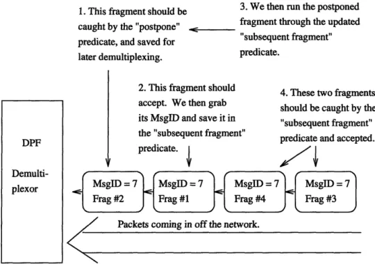
Figure 2-4 illustrates this process, and the following paragraphs describe in detail how
the DPF language supports it.
The problem with out-of-order fragments is that most of the header information needed
for demultiplexing appears only in the first fragment. It is usually possible to determine if
an application may be interested in a packet's out-of-order fragment, even without having
the packet's header yet. This is crucial if we hope to identify fragments for postponement.
So, postpone predicates can be written that identify which fragments should be saved away
for checking later, when the first fragment arrives. These predicates are marked with the "P" token. If one such predicate accepts a packet, that packet is presumed to be an out-of-order fragment and is saved by the DPF implementation for demultiplexing once the first
fragment arrives. Care should be taken in writing the "P" predicate such that it does not
catch the first fragment; one would like the first fragment to be accepted by other predicates in the filter instead of it being postponed itself.
The first fragment will indicate the unique message ID by which one can recognize the postponed and subsequent fragments. This message ID is found in a bitfield that is well-defined within that packet's protocol. The location of this bitfield should be well-defined in
another predicate, the subsequent fragment predicate. This predicate appears in brackets
at the end of the filter. In order to properly access the message ID, two constraints need
to be set on this predicate. First, the bitfield in the last atom of this predicate's "&&"
chain must define the location of the unique message ID. Second, this bitfield should have constant delimiters and not be part of an indirect load. Care should be taken in writing these subsequent fragment predicates because most of the fragmented packet's header
infor-mation, including source and destination addresses and port/socket numbers, will appear
only in the first fragment. Usually, it is only necessary to check for the correct protocol and the unique message ID.
When a packet filter is initially inserted, this bracketed subsequent-fragment predicate
is saved away for later use. Only the unbracketed predicate(s), including the postpone predicate(s), are actually inserted into the DPF system. At least one of these predicates should be a postpone predicate, unless the filter writer is somehow certain that fragments will never arrive out of order. The bracketed subsequent-fragment predicate is not activated
until the first fragment arrives.
Once the first fragment arrives, the DPF system lifts the value in the message-ID bitfield
1. This fragment should be 3. We then run the postponed caught by the "postpone" < fragment through the updated
"subsequent fragment" predicate, and saved for "subsequent fragment" later demultiplexing. predicate.
2. This fragment should 4. These two fragments
DPF Demulti-plexor
accept. We then grab
should be caught by the its MsgID and save it in "subsequent fragment" the "subsequent fragment"
predicate and accepted. predicate.
MsgID = 7 MsgID 7 MsgID = 7 MsgID = 7 Frag #2 Frag #1 Frag #4 Frag #3
Packets coming in off the network.
Figure 2-4: Illustration of fragment postponement and demultiplexing. Fragments arriving
before the first fragment should be postponed. The first fragment should be accepted,
and its message ID should be used to demultiplex postponed and subsequently arriving
fragments.
as the constant to which we are comparing the message-ID bitfield, thus creating a boolean operation that checks subsequent fragments for that message ID. This predicate is then
inserted, merged with the other filters, and dynamically compiled into machine code. It
is then used to check all subsequently-arriving and previously arrived fragments that had been postponed by predicates from the same filter.
Postponed fragments are placed in a queue of fixed length. When the queue fills, the oldest fragment is discarded, and the next incoming fragment is placed at the end of the queue.
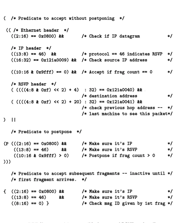
An example of a filter that checks for fragmented packets is given in Figure 2-5. The protocol for which this filter checks is the Reservation Protocol (RSVP) [22]. RSVP is a protocol intended for use in allocating network resources and setting up communication paths immediately before a multicast or unicast. RSVP packets are usually quite large
and are often subject to fragmentation. In this filter, one predicate is intended to accept
the first fragment, and contains information specifying a particular RSVP session. The
( /* Predicate to accept without postponing */ (( /* Ethernet header */ ((2:16) == 0x0800) && /* IP header */ ((13:8) == 46) && ((16:32) == Oxl21aOO09) && /* Check if IP datagram /* protocol == 46 indicates RSVP /* Check source IP address
((10:16 & Ox9fff) == 0) && /* Accept if frag count == 0
/* RSVP header */ ( ((((4:8 & Oxf) << 2) + 4) ( ((((4:8 & Oxf) << 2) + 20) ) 1 : 32) == Ox121aO040) && /* destination address : 32) == Ox121aO041) &&
/* check previous hop address -- */
/* last machine to see this packet*/
/* Predicate to postpone */
(P (((2:16) == Ox0800) && ((13:8) == 46) && ((10:16 & Ox9fff) > 0)
/* Make sure it's IP /* Make sure it's RSVP
/* Postpone if frag count > 0
/* Predicate to accept subsequent fragments -- inactive until
/* first fragment arrives. */
{ ((2:16) == Ox0800) && ((13:8) == 46) && ((8:16) == 0) }
/* Make sure it's IP /* Make sure it's RSVP
/* Check msg ID given by 1st frag */
Figure 2-5: DPF filter recognizing a possibly fragmented RSVP packet. Fragments are post-poned by checking the IP fragment field. Fragment reassembly is performed by recognizing all fragments that have the message ID given by the first fragment.
second predicate, ORed to the first, is the postpone predicate. Both of these predicates
are activated upon the filter's insertion into the DPF system. The postpone predicate does
not check for any information in the RSVP header. Since fragmentation should be done
at the IP layer, the RSVP header will appear only in the first fragment. So, the postpone
and subsequent fragment predicates should contain only atoms checking bitfields in the IP header. In this example, the postpone predicate need only check if the packet is of the RSVP/IP protocol and if the fragment count is greater than zero. This last atom will
ensure that the postpone predicate does not catch the first fragment, whose fragment count
will be equal to zero. Likewise, the subsequent fragment predicate will contain only atoms checking the IP header. The last atom contains the bitfield in which the unique message ID is located, thus meeting the constraints for a subsequent fragment predicate. This bitfield as written happens to be compared to zero, but any constant could be written here. It will only be overwritten by the actual message ID from the first fragment.
Chapter 3
DPF Implementation
3.1 Overview
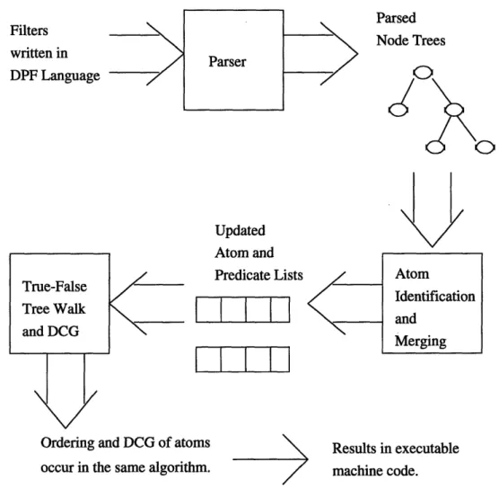
This chapter describes the implementation of DPF's parsing, merging, and dynamic code generation (DCG) of filters. These are executed in sequential order in DPF's
implemen-tation, and will be described in the same order in this chapter. Figure 3-1 illustrates the
process of parsing, merging, and generating code for DPF filters.
First, a DPF filter must be parsed into a tree-like structure before it is submitted to the
demultiplexor. This parser's implementation is described in section 3.2.
Next, DPF attempts to merge the new filter with those that were previously inserted. This is done by (1) identifying the atoms and predicates in the new filter, (2) comparing
these atoms to those of previously activated filters, (3) arranging the updated collective
set of atoms into a queue, ordered in descending order of number of appearances, and (4) performing all the necessary bookkeeping to keep track of which predicates atoms belong to. We call this set of operations the merging of filters, because it is here where we find overlaps
between all filters and try to take advantage of them by merging the similar instructions.
These operations are described in section 3.3.
Immediately thereafter, code is generated for the whole updated collection of atoms. Atoms are dequeued and code is generated for them one at a time, in a specific order. This ordering is important, as it ensures that each atom is executed no more than once. The ordering is such that, when the code is subsequently executed, it follows a path down a binary true-false tree of atoms. This binary true-false tree has boolean operations (the atoms) as nodes, with each node having one branch representing the true condition and the
Filters
\
written in DPF Language
Ordering and DCG of ato occur in the same algorith
Updated Atom and Predicate Lists
I
L
I
I
ms Im. Results in executable machine code.Figure 3-1: Illustration of the separate steps in DPF's implementation. Filters are parsed,
then atoms are recognized and merged, and then dynamic code generation is performed on
each atom in an order that traverses a true-false tree.
other branch representing the false condition. Atoms that appear in the most filters are at
the top of this tree, with the least common atoms appearing as leaves. Execution begins at the top of this tree and continues until a leaf is reached, at which point it is known which filter (if any) should accept the packet. Traversal of this tree is described in section 3.4.
After laying the groundwork of how atoms are merged and how their code generation is ordered, we then discuss additional operations which were later added to these basic oper-ations. The first is merging atoms that differ only by the constant to which packet bitfields are compared. These are called disjunctive atoms, because they are considered to evaluate
to true if just one of the constants matches the packet and false if none do. Disjunctive
atoms were added because they can vastly improve DPF's demultiplexing performance for a Parser Parsed Node Trees Atom Identification and Merging I 1'1
X/
majority of filters. The functions that build and manipulate disjunctive atoms are described in section 3.5
A second additional operation is handling filter priorities. Often, a packet can match several filters' specifications, but only one should accept it for security reasons. Most
demultiplexors in the literature arbitrate with priorities, such that only the highest-priority
filter actually accepts a packet. How this is done in DPF is described in section 3.6. We then close with a discussion of per-atom dynamic code generation. The DCG func-tions are made as machine-independent as possible, with instruction emissions being per-formed by macros that are defined in machine-dependent header files. This was done to
simplify porting DPF to different architectures. Some standard compiler optimizations that
were applied to DCG are also described.
3.2 Parsing DPF
DPF filters must be first parsed into data structures that can be easily manipulated by the
filter merging algorithms. In this section, we first discuss the parser's basic
implementa-tion, and then close with a discussion of how certain constraints on parsed DPF filters are
enforced.
3.2.1 Parser Implementation
The parser module was built using the standard parsing tools flex and bison, with the
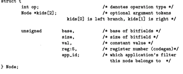
grammar presented in Figure 2-1. DPF tokens are parsed into a Node structure, shown in Figure 3-2. It contains:
1. An integer denoting the operation type, if the token is an operator;
2. Two pointers to other node structures, representing the arguments to an operator
token (none, one, or both may be initialized);
3. Two integers denoting the base and size of a packet bitfield, initialized only if this is a bitfield token;
4. An integer containing the constant, only if this is a constant token; 5. A set of bits used by the dynamic code generator for register allocation;
struct {
int op; /* denotes operation type */
Node *kids[2]; /* optional argument tokens
kids[O] is left branch, kids[1] is right */
unsigned base, /* base of bitfields */
size, /* size of bitfield */
val, /* constant value */
reg:5, /* register number (codegen)*/
app-id; /* which application's filter
this node belongs to */
} Node;
Figure 3-2: DPF node structure into which each DPF token is parsed.
6. An integer that uniquely identifies the application whose filter from which this token originates, supplied by the application, usually the process identifier (PID).
Collectively, these entries represent all the information needed to generate the code for a filter.
The parser will attempt to assemble all tokens' node structures into a single tree. Since
a legal packet filter is really just one large boolean function, it should always be possible to do this. The only exceptions are packet filters that handle fragmentation; the bracketed predicates are assembled into a separate node tree, to be inserted and merged by DPF at a
later time.
A legal DPF tree should consist of one long list of logical operator nodes ("&&" and
'II"), whose arguments consist of relational operator nodes. The arguments to these relop
nodes will consist of the functions on bitfields and the constants to which we are comparing
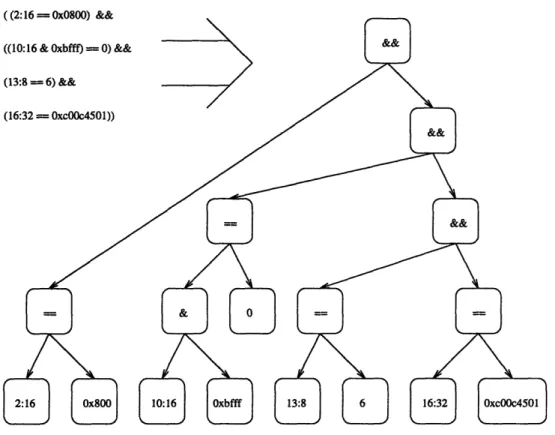
them. A small sample filter and its parsed tree structure are given in Figure 3-3.
3.2.2
Parse Trees' Canonical Ordering
Immediately after a filter's parse tree is constructed, some constraints on the ordering of
nodes within the parse tree are enforced. These constraints define the canonical ordering of
nodes within a tree, and serve to make the task of identifying atoms and predicates easier.
In particular, node trees should abide by the following:
Figure 3-3: Sample TCP filter with parsed node structure.
1. Logical operators ("&&" and "11" tokens) have only relational operators and other
logical operators as arguments, with the relational operators as the "left" argument
and the logical operators as the "right" argument;
2. Bitfields (or functions thereof) always appear as the "left" argument and constants
always appear as the "right" argument;
3. Constants are folded.
The sample parsed filter in Figure 3-3 abides by the canonical ordering.
This canonical ordering of argument nodes makes filter merging more efficient in two ways. First, atoms are easier to recognize in newly-submitted filters because the logical
operations will always be expected along the right-most branch of a tree, with the relational
operators always to the left. This way, atoms can be identified only by checking the left branch for rel-ops. Second, atoms are easier to compare with each other because constants will always be a relop's right branch and the bitfield will always be on the left. This cuts
and dynamic code generation faster.
Parsed node trees are canonicalized by swapping "left" and "right" nodes as appropriate. In practice, most legal packet filters will already exhibit most of the requirements of this canonical ordering. We expect most filters to be written such that, for example, constants appear in the right branch and bitfields appear in the left branch of a rel-op node. How-ever, we still enforce this ordering to prevent a poorly-written filter from hurting DPF's performance.
3.3 Merging Filters
This section describes the algorithm by which DPF finds and merges instructions found in multiple filters. The goal of DPF's filter merging algorithms is to ensure that all the common atoms in mergeable filters are executed at most once when demultiplexing a packet.
This algorithm is run whenever a new filter is inserted or an inactive filter is removed. An insertion or removal means that the collective set of active atoms has changed, and we should determine again how often and in which filters atoms appear. Immediately after the common atoms are identified and merged, dynamic code generation is run.
Subsection 3.3.1 describes the operations that occur whenever a filter is inserted. We
will walk through an example to help illustrate these complex set of operations. Then,
subsection 3.3.2 describes what happens when a filter is removed.
3.3.1 Inserting New Filters
Once the filter is parsed and canonicalized, its atoms are identified and compared with
the atoms of previously-inserted filters. The predicates to which atoms belong are also
identified. A relational operator is always the top node of an atom, and a list of atoms
connected by "&&" operators constitutes a predicate.
After atoms are identified and compared, they are inserted into a global atom queue,
ordered such that the most common atoms appear first and the least common atoms appear
last. This queue is later used during the true-false tree walk to determine the order in which
atoms are subject to dynamic code generation.
In the following subsection, the identification of atoms and predicates in a new filter is
discussed in more detail. The next subsection then describes the data structures involved
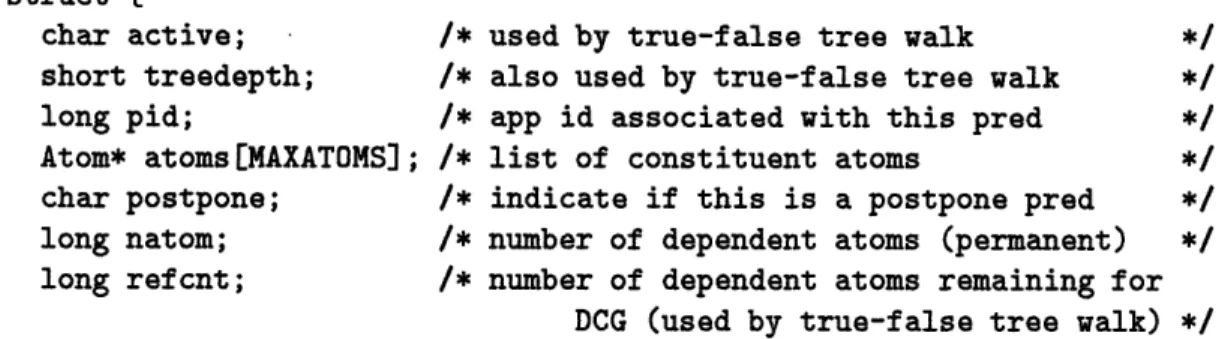
struct {
char active; /* used by true-false tree walk */
short treedepth; /* also used by true-false tree walk
long pid; /* app id associated with this pred */
Atom* atoms[MAXATOMS]; /* list of constituent atoms */
char postpone; /* indicate if this is a postpone pred */
long natom; /* number of dependent atoms (permanent) */
long refcnt; /* number of dependent atoms remaining for
DCG (used by true-false tree walk) */
} Predicate;
Figure 3-4: DPF Predicate structure
in storing these new atoms and predicates in the DPF system, and how these new atoms
are compared with previously-inserted atoms and inserted into the atom queue.
Identifying New Atoms and Predicates
First, we iterate down the node tree, identifying atoms and assembling them into predicates.
At the beginning of this process, a Predicate structure is initialized. Space is allocated
to hold pointers to the constituent atoms, along with some run-time information. This
run-time information consists of:
1. The ID of the application that submitted this predicate's filter.
2. Two copies of the number of atoms in this predicate (length of the atom pointer array). One is a static count while the other is modified in the true-false tree walk. 3. A postpone boolean indicating if matching packets should be postponed.
4. An active boolean used in the true-false tree walk. 5. A treedepth integer, also used in the true-false tree walk. See Figure 3-4 for the definition of the predicate structure.
The identification of atoms and predicates works as follows. When a "&&" operator is encountered, we look down its left branch for an atom, then continue down the right
branch. When a "II" operator is encountered, then we know that another predicate must
exist; another predicate structure is allocated, and the one currently being assembled is copied into it. We then continue assembling the first predicate by iterating down the left
struct {
long npred; /* number of dependent preds (permanent)*/
long refcnt; /* number of dependent preds (used by true-false tree walk) */ Predicate* dp[MAXPREDS]; /* list of dependent preds */
Node* relop; /* the relop that this atom represents */
} Atom;
Figure 3-5: DPF Atom structure
branch, and we assemble the second predicate by iterating down the right branch. If a "P"
operator is found, then we know that the current predicate is a "postpone" predicate, and
the postpone boolean is set to "true".
Atoms are identified when relops are encountered. An Atom structure is initialized that
contains the relational operator's subtree in addition to some other run-time information.
Figure 3-5 shows the atom's structure. The run-time information consists of:
1. An array of pointers to the predicates that include this atom (called dependent
pred-icates).
2. Two copies of the length of the predicate pointer array (the number of predicates
containing this atom). Again, one is a static counter, while the other is modified during the true-false tree walk.
An example of the results of atom and predicate identification is shown in Figure 3-6. Here, the same filter as in Figure 3-3 is shown with the properly identified atoms and predicate. Some of the atom and predicate structure entries are also shown. In particular, the dependent predicate count is shown set to one and all pointers (relop nodes, atoms, and the predicate) are shown. The other entries (not included in the figure) will be filled in later on in the filter merging operations.
The Atom Queue and Predicate List
The last two data structures to be described in this section are the two global lists that keep track of all currently active atom and predicate structures. These two lists always represent the complete and current state of the DPF system. They collectively contain all the information needed to generate the machine code.
((2:16 = Ox0800) &&
Predicate #1: natom = 4 ((10:16 & Oxbfff) = 0) && postpone = 0
N~ ~~~~~~~ postpone = 0
(13: (16:
Figure 3-6: Sample TCP filter with atoms and predicate identified.
The predicate list is unordered, and acts only as a global repository of active predicates. The atom list is treated as an ordered queue. Atoms in the atom queue are ordered in decreasing order of number of appearances in all active filters. So, the most commonly-occurring atoms are at the beginning of the queue, while atoms appearing only once are at
the end.
Once an atom structure has been built and inserted into its predicate structure, it is
compared with each atom that already exists in the atom queue. This is done by comparing
the rel-op operators and their arguments. If the new atom does not match any existing atom,
it is simply placed at the end of this queue. If a match is found, then the following occurs: 1. The existing atom's dependent predicate count is incremented.
2. The new atom's dependent predicate pointer is added to the existing atom's dependent
predicate list.
3. The new atom structure is discarded.
4. The updated atom is swapped with the atom(s) ahead of it in the queue, if necessary, II I I I II I I I l
I 1.1
until the queue invariant is again observed.
Once a node tree has been completely traversed and all atoms have been identified and inserted into the atom queue, the new predicate(s) are added to the predicate list, thus concluding the insertion operation. Execution then continues with the true-false tree walk.
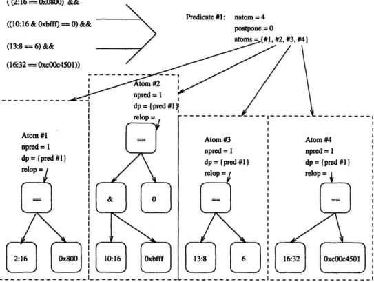
Figure 3-7 shows an example of the effect of adding more filters to the system, illustrating what happens when filters with common atoms are inserted. In this example, all four filters
share an atom comparing 2:16 to the same value. This atom appears at the front of the
queue. It is followed by two atoms which each appear in two filters. The tail of the queue is occupied by an atom appearing in only one of the filters. All atoms contain their up-to-date
multiplicity and list of pointers to dependent predicates. The predicate list is not intended
to be in any particular order. But, the predicate structures in this list must contain the
number of dependent atoms and pointers to those atoms. They must also contain their
postpone status and the pid of the process that submitted them. Dummy pids are shown
in this figure.
3.3.2
Removing Inactive Filters
Filters are removed when its application terminates. The application ID is simply passed
to DPF, which iterates through both global lists and removes the relevant information.
First, we iterate down the global atom queue. For each atom, we iterate down its
dependent predicate list. If a predicate's PID matches the given application ID, then that
predicate's pointer is zeroed, the atom's dependent predicate counter is decremented, and
atoms are rearranged in the queue as necessary to maintain the atom queue invariant. If
the dependent predicate counter is decremented to zero, then this atom no longer appears in any active filters, and its pointer is freed.
Second, we iterate down the global predicate list. Whenever a predicate's PID matches the given application ID, its pointer is freed. If a filter consists of more than one predicate, all associated predicates are deleted, since they all share the common application ID.
After removing the inactive predicates and updating or removing their dependent atoms, dynamic code generation is performed on the resulting set of atoms.
--- I I Atom #2 I nnrr--A = I Atom #1 npred = 4 dp = (#1, #2, #3, #4) Atom Queue
( (2:16
= 0x0800)
&&
((10:16 & Oxbfff) = 0) &&
(13:8 = 6) && (16:32 = 0xc00c4501)) ((2:16 = 0x0800) && ((10:16 & Oxbfff) = 0)) ((2:16 = 0x0800) && ((13:8 = 6)) ((2:16 = 0x0800)) Atom #3 npred = 2 dp = (#1, #3) Atom #4 npred = dp = {#) }
Figure 3-7: Four TCP/IP filters with the resulting atom queue and predicate list.
Predicate List Predicate #1: natom = 4 postpone = 0 atoms = (#1, #2, #3, #4) pid = 1 Predicate #2: natom = 2 postpone = 0 atoms = {#1, #2) pid = 2 Predicate #3: natom = 2 postpone = 0 atoms = {#1, #3) pid=3 Predicate #4: natom = I postpone = 0; atoms = {#1) pid = 4 dp = 1#, #2) I vol _ l I I I I I I I I I I II _
-i
3.4 The True-False Tree
This section describes the traversal of the true-false tree of atoms. The true-false tree
is a binary tree with boolean operations (the atoms) as nodes, "true" conditions as the left branches and "false" conditions as right branches. Execution of the machine code is intended to begin at the top of this tree and follow a single path to one of the leaves. The purpose of this is to ensure the following properties in the machine code:
1. The path of execution down the tree should not execute any atom more than once. 2. Atoms appearing in the most predicates are executed first, and those appearing least
often are executed last. This keeps the tree small and ensures that the most rejected packets are rejected early.
3. Execution does not end until a leaf is reached. Here, and only here, can a judgment be made regarding all active predicates with respect to that packet. Also, only here can it be conclusively determined which predicate, if any, accepts the packet.
To help illustrate what a true-false tree for a particular set of filters looks like, Figure 3-8 shows the true-false tree for the filters given in Figure 3-7.
We detail the traversal of the true-false tree itself in the following subsections. The
per-atom code generation that occurs during this traversal is described in section 3.7.
Brief Overview
In brief, there are three mutually recursive functions that perform the true-false tree traver-sal: genatom, true_emit and false_emit. genatom first dequeues an atom from the atom queue. If the atom exists in predicates that can still accept from the current location in the true-false tree, it emits the code for that atom, and then calls true_emit and false_emit to emit the "true" and "false" branches of that atom, respectively. If the atom exists in no predicate that can still accept, genatom will call just itself on the next atom in the queue. true_emit calls genatom again, after possibly emitting code that accepts the packet.
Ac-ceptance code is emitted if the last atom in a predicate had just been emitted. false_emit
also calls genatom again. Both true_emit and false_emit perform bookkeeping on the atoms and predicates that keeps track of which predicates can accept at different points
in the tree. The operation of these functions is described in more detail in the following paragraphs. To help illustrate this algorithm, pseudocode is presented in Figure 3-9.
Setup
First, before calling genatom, all the atoms and predicates must be prepared for the tree
walk. Each predicate's atom count is copied into its refcnt entry, as is each atom's predicate count. Also, each predicate's active boolean is set to "true". Being "active" means that, in a given location in the true-false tree, that predicate can still possibly accept a packet, but all of its atoms have not been executed yet. At this point, before any atoms are executed (the top of the tree), all predicates are active.
genatom
Then, genatom is called. genatom first dequeues the first atom in the atom queue. It then
determines if this atom should be a node at this point in the true-false tree. It should
be a node only if it is part of a predicate that is still active. genatom determines this
by iterating down this atom's dependent predicate list, looking for predicates with a true
active boolean. As soon as one is found, it knows that a predicate exists that is still a
candidate for accepting the packet at this point in the true-false tree, but would not have
done so yet, and so this atom should be a node at this point in the true-false tree. genatom
then generates code for the atom and then executes true_emit and false_emit, and then
ends by backpatching and re-enqueueing the atom.
If none of this atom's predicates are still active at this point in the true-false tree,
then it should not be emitted. However, the next atom may need to be emitted. So, in
this case, genatom simply calls itself, thereby dequeuing the next atom in the queue and
possibly setting it up as a node in the tree. After returning from this call, the first atom is re-enqueued.
Each atom's block of machine code will end in a branch instruction. genatom emits a
branch instruction such that the branch is taken if the relational operator is false. Execution
will simply continue down the "true" branch if the atom is true. However, the offset is left
out initially, in anticipation of true_emit emitting the "true" branch in the future. Later,
Predicate list T Atom queue T F T Accept #2 F T Return Accept #3 Return turn ject) turn T Accept #1 Return Return
Figure 3-8: Sample true-false tree given the set of sample atoms and predicates in Figure 3-7. "(reject)" indicates a return with no acceptances having occurred, so the returned PID is zero. Otherwise, the PID returned is the PID of the most recently accepted predicate. Subsequent acceptances overwrite previous acceptances. Execution of machine code will always follow a sequence of arrows to one of the "returns" at the bottom of the tree.
Atom #1 Atom #2, Atom #3, Atom #4,
Preds: Preds: Preds: Preds: 1,2,3,4 1,2 1,3 1 Pred #1 Atoms: 1,2,3,4 Pred #2, Atoms: 1,2 Pred #3, Atoms: 1,3 Pred #4, Atoms: 1 I 1..
tree-walk; arguments: none; returns: pointer
foreach a:atom in atom queue do foreach p:pred in a.plist do
p.refcnt := p.natom p.active := TRUE
enqueue(genatomo) ;; Do tree walk
backpatchleaves() ;; Leaves jump to return instruction return(code-handle) ;; Return pointer to machine code genatom; arguments: none; returns: atom
execflag:int := 0
a:atom := dequeue( ;; Get next atom in queue if (a == NULL) then return(NULL)
foreach p:pred in a.plist do ;; Look for predicates that can still accept if (p.active == TRUE) then
branchptr:instr := atom.emit(a) ;; Emit atom's code and return its branch instruction enqueue(trueemit(a)) ;; Emit "true" branch
patch(branchptr) ;; Backpatch
enqueue(false-emit(a)) ;; Emit "false" branch execflag := 1
break
if (not execflag) then enqueue(genatomo) ;; If this atom not emitted, try next atom return(a)
trueemit; arguments: a:atom; returns: atom
foreach p:pred in a.plist do ;; Look for predicates that accept at this point in tree
if (p.active
and -p.refcnt == 0) then
accept emit(p.pid,p.postpone)
foreach q:pred in predmasterlist do ;; Deactivate predicates of same PID or lower priority if (q.active and (q.pid == p.pid or q.priority > p.priority)) then
q.active := FALSE q.depth := cur-depth
ta:atom := genatom( ;; Recursion: continue walking tree
foreach p:pred in a.plist do ;; Reactivate predicates if (curdepth() == p.depth) then p.active := TRUE if (p.active) then p.refcnt++
foreach q:pred in pred-masterlist do
if (cur-depth() == q.depth) then q.active := TRUE return(ta)
falseemit; arguments: a:atom; returns: atom
foreach p:preds in a.plist do ;; Deactivate all dependent predicates if (p.active) then p.depth := cur-depth()
p.active := FALSE
fa:atom := genatom( ;; Recursion: continue walking tree
foreach p:preds in a.plist do ;; Reactivate preds if (cur-depth() == p.depth) then p.active := TRUE return(fa)
I 1.1
true_emit
After emitting code for an atom, genatom calls trueemit, which generates the true branch
of the just-emitted atom.
true_emit
first iterates down the just-emitted atom's dependent
predicate list, decrementing each predicate's refcnt. refcnt keeps track of the number of
atoms in that predicate that have not been emitted yet, so this number must be decremented
in each predicate that depends on the just-emitted atom. If a predicate's
refcnt
reaches
zero, then all the atoms of that predicate have been emitted, and that predicate should
accept. An instruction that places that predicate's PID into the return register is emitted.
We also emit an instruction that places the postpone boolean in a predetermined address.
However, the return instruction itself is not yet emitted. Actually, execution is intended to
continue. Subsequent predicates may later accept, and their PIDs will overwrite this one. This may seem strange, but there is a good reason for doing this. Only one application should accept a packet. Even if several predicates can accept, there should be a way of arbitrating between them. Our way of arbitrating is by giving the packet to the application
with the predicate having the most atoms - so, predicate acceptances at the bottom of the
true-false tree overwrite earlier acceptances. This is an admittedly quick and dirty way of arbitrating between multiple accepting filters, but it also serves to cheaply enable a more intelligent way (prioritizing predicates) that will be described in section 3.6.
After emitting the code that accepts a predicate, true_emit sets the just-accepted
pred-icate's active boolean to "false", and sets its depth to the current level in the true-false
tree. This records where in the tree this predicate was deactivated. At the end of true_emit,
this predicate is reactivated, but we must be sure that only this call of true_emit is the one that reactivates this predicate. (A global treedepth counter is incremented at the be-ginning of genatom and decremented at its end. When determining if a predicate should be reactivated, its depth is compared to this global counter. If they are equal, the predicate is
reactivated.) Then, true_emit calls genatom. trueemit then finishes by reactivating all
predicates that it deactivated.
false_emit
Next, the original call to genatom calls false_emit. false_emit simply deactivates all
none of these predicates will accept. falseemit then calls genatom, and then reactivates all these predicates. The treedepth must again be saved away in each predicate, as a way
of ensuring that only this call of false_emit actually reactivates these predicates, just as
in trueemit.
Ending the Recursion
The bottom of these functions' mutual recursion is reached when genatom tries to dequeue
an atom but finds an empty queue. This means that a leaf in the tree has been reached. In this case, a branch to a return instruction at the end of the machine code is set up, and
will be backpatched at the conclusion of the true-false tree traversal.
When the top-level genatom call returns, the entire true-false tree has been emitted, and
the atom queue has been reconstructed. At this point, the return instruction is emitted,
and the unresolved branches at the leaves of the true-false tree are backpatched. Then,
the DPF system returns the machine code handle as a pointer to a function, which can be
subsequently called to check incoming packets. The prototype of this function pointer will be discussed in section 3.7.
3.5 Disjunctive atoms
Often, atoms will differ only by the constant to which a bitfield is being compared. The
bitfield (or the function of that bitfield) and the relational operator are the same. This
should happen very often in practice, because there will often be several filters that check for the same protocol stack, but differ by only an address or a port number. For example,
in TCP/IP and UDP/IP, filters' IP portions are identical, but the port numbers in the TCP
or UDP portions differ. Other filter systems described in the literature have been designed with this idea in mind [4, 21]. Combining these atoms that look up the same bitfield but compare against different values can significantly reduce the number of atoms that need to be manipulated by the DPF system, thus enhancing its demultiplexing performance. The
resulting merged atom is called a disjunctive atom, because for it to evaluate to "true", the
packet bitfield needs to match only one of the values. In fact, at most one value can be