HAL Id: cea-02332306
https://hal-cea.archives-ouvertes.fr/cea-02332306
Submitted on 24 Oct 2019
HAL is a multi-disciplinary open access
archive for the deposit and dissemination of
sci-entific research documents, whether they are
pub-lished or not. The documents may come from
teaching and research institutions in France or
abroad, or from public or private research centers.
L’archive ouverte pluridisciplinaire HAL, est
destinée au dépôt et à la diffusion de documents
scientifiques de niveau recherche, publiés ou non,
émanant des établissements d’enseignement et de
recherche français ou étrangers, des laboratoires
publics ou privés.
Radio-Frequency Hands-on for Nuclear Fusion Master
Students
Julien Hillairet, Joëlle Achard, Riccardo Ragona
To cite this version:
Julien Hillairet, Joëlle Achard, Riccardo Ragona. Radio-Frequency Hands-on for Nuclear Fusion
Master Students. European Journal of Physics, European Physical Society, 2019,
�10.1088/1361-6404/ab56df�. �cea-02332306�
Radio-Frequency Hands-on for
Nuclear Fusion Master Students
Julien Hillairet
1, Joëlle Achard
1, Riccardo Ragona
21
CEA, IRFM, F-13108 St-Paul-Lez-Durance, France
2
Laboratory for Plasma Physics, ERM-KMS, 1000-Brussels, Belgium E-mail: [email protected];
Abstract
High-power Continuous Wave Radio-Frequency (RF) systems in the megawatt range of power are commonly used in nuclear fusion experiments. Such kinds of RF systems being rather rare, master students do not know how these systems are done in practice, even students engaged in nuclear fusion courses. This is the reason why, as part of the French and European masters in fusion physics and technologies, dedicated practical work on topics related to plasma RF heating are proposed to students. During few days, these students discover how to perform RF measurements and succeed in characterizing real-scale components used in plasma RF heating experiments. This paper details four hands-on which have been conducted for eight years with few tens of students having no prior knowledge in RF engineering.
Keywords: Radio-Frequency, High Power, Plasma Heating, Nuclear Fusion, hands-on
Introduction
The objective of nuclear fusion research is to demonstrate the scientific and technological feasibility of nuclear fusion (as opposed to nuclear fission) to create electricity. However, in order to achieve the necessary conditions allowing light nucleus to fuse, plasmas of temperature larger than 100 million degrees must be generated and sustained. Devices called tokamak [1] are developed and used all around the world to study the magnetic confinement of such plasmas. WEST[2] (previously known as Tore Supra [3]), is a superconducting tokamak located in Cadarache (France) which has demonstrated the sustainment of long plasma pulses (up to 6 minutes 30 seconds)[4].
In order to sustain these long plasma pulses, a part or all the plasma current which is circulating inside the plasma ring must be generated non-inductively. This additional plasma current is driven on WEST via the Lower Hybrid (LH) RF system [5,6]. High power Radio-Frequency sources (klystrons) generate up to 7 MW at 3.7 GHz, which are carried through 25 meter-long transmissions lines (rectangular waveguides) up to the LH antennas facing the edge plasma. These antennas (two on WEST) are made of rectangular waveguide phased arrays which excite a plasma wave mode that ultimately accelerates electrons and create an
The Ion Cyclotron Resonance Heating (ICRH) is another RF system used to increase the plasma temperature by launching RF waves with frequencies are equal to the gyro-frequency of one ion species of the plasma [8]. In WEST, the ICRH system can generate up to 9 MW in the frequency range of 48-60 MHz, where rigid coaxial lines feed three antennas made of an array of 4 short “straps” [9]. Future IC systems are also under design for the next generation of fusion tokamaks [10].
In order to train the future fusion scientists and engineers, French and European master programs exist to provide teaching on plasmas sciences and associated technologies. These master’s programs deal with most scientific and technological fields related to the ionized media via theory, numerical modelling, material sciences, cryotechnology and superconductivity and instrumentation in extreme environments. However, for a vast majority of them, no dedicated courses are provided on RF sciences and technologies, despite their large use on fusion research facilities.
During two weeks at the beginning of the civil year, both French and European master students gather in the Cadarache research centre in order to participate in small groups to hands-on organized by fusion researchers. The topics of these hands cover the large spectrum of fields used
2
analysis, virtual reality, etc. Among these hands-on, some are devoted to RF component measurements and analysis and are described in this paper. Section 1 details the LH-specific hands-on devoted on two particular components of the LH antennas used on WEST. Section 2 focuses on ICRH-specific hands-on regarding high voltage probe calibration and the design of a possible future ICRH antenna. The last section concludes with the student’s and author’s feedbacks on these hands-on. Because some of the components used in these hands-on are very specific to high power RF and especially fusion applications, in particular for LH topics, it is probably not easy to reproduce them in other teaching places. The last topic described in this paper however, only use phase shifters and 3dB hybrid junctions which are much more commonly available in laboratories.
Lower Hybrid frequency range hands-on
Two hands-on have been proposed to the students on two RF components constituting the real WEST LH launchers: a mode converter (in red in Figure 1) and a “multijunction” (in blue in Figure 1). These RF components have multiple functions, but the main one is to split the RF power coming from the klystron to numerous waveguides facing the plasma. These two components and their associated hands-on are described in the sub-sections below.
Figure 1. CAD view of a WEST Lower Hybrid antenna (aka “LH1”). The red part is the TE10-TE30 Mode Converter. The Blue part is the
“multijunction”. Dimensions: 0.7 x 0.7 x 5 m. Weight: a few tons.
TE
10-TE
30Mode Converter
A mode converter is an RF device which aims to convert an electromagnetic mode of propagation in a waveguide into another mode [11]. In particular, the TE10-TE30 mode converter converts a low order incident Transverse Electric mode (TE10) into a higher-order TE mode (TE30)[12][13]. Once this mode conversion performed (Figure 2), the power is then split into three independent waveguides by placing two thin metallic walls (in the E-plane) at the zero electric field location of the TE30 mode section. Thus, three TE10 mode waveguides are obtained and the device has thus divided the power in three. This device is used on WEST to
split in three the RF power in the vertical direction of the antenna, in order to feed three rows of waveguides in each half parts of the LHCD antenna (cf. Figure 1).
Figure 2. CAD Internal view and its associated RF modelling (electric field).
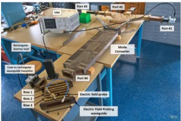
During this hands-on, students measure the RF performances of a TE10-TE30 mode converter prototype (Figure 4) which has been developed for the LH1 antenna [14]. The performances of an RF device being generally expressed via scattering parameters (or S-parameters), a general introduction to the S-parameter is given to the student groups in the first hours of the hands-on.
Figure 3. Illustration of the measurement setup.
Figure 4. Picture of the mode converter setup
Like a role-playing game, the advisors ask the students to act as an RF technician who have been asked by his/her head
to characterize this TE10-TE30 mode converter prototype and to report its performances as soon as possible. Unfortunately, the prototype had not been built exactly as designed: during the brazing operation which has been performed to assemble all the stainless-steel and copper parts of the structure, the mechanical pressure was not homogeneous, leading to less than a millimetre local deformations. This is however sufficient to perturb the RF performances: the mode converter and its splitter is found to not split evenly the power in three (-4.77 dB) but instead to -5.4, -4.2 and -5.3 dBfor the left, central and right branches respectively at the frequency of interest (3.7 GHz).
However, the students are not told of this fact (which retrospectively was discovered once the RF measurements had been made during prototype acceptance test). They thus find unexpected results and the supervisors act as if they were surprised, telling the students that the “RF design” is supposed to be perfect. Generally puzzled by their finding, very few students guess at first that a problem may have occurred during manufacturing. Students are thus asked how sure of their measurements they are, which is a good opportunity to discuss and explain the importance of calibrations, power conservation, statistics and uncertainties in experimental physics.
In order to help them to find the origin of the mode converter problem, students are provided the opportunity to measure the electric field at the end of the mode converter, in the TE30 section (output), using a dedicated waveguide pierced by an array of very small holes inserted between the mode converter and the 3-ways adapter and an appropriate probe collecting a fraction of the electric field propagating inside the waveguide (Figure 4). Once measured in various positions (Figure 5), students are asked from these data to deduce the mode content inside the mode converter, i.e. the amplitude of the modes propagating inside the structure to complete their analysis. This task requires the students to make a numerical model of the electric field Ey inside the
waveguide, as a combination of TE modes (assuming only forward waves for simplicity):
with the guided wavenumber, k0 the
wavenumber in vacuum and a the large side of the waveguide. Coefficients an are unknown and represent the
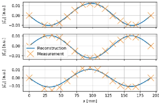
mode content coefficients. Students must solve the inverse problem to deduce the an coefficients (Figure 6). The mode-converter prototype fails to convert 100% of the input mode TE10 into the TE30 mode. Solving for the an coefficients leads
to number around 76% to TE30 mode, 13% to TE10 mode and the rest into other modes. Since 2011, this problem had been solved using various approaches and computer languages by the students: from least-squares fits to Fourier transforms, with Matlab, Python, Excel or even compiled languages such
as Fortran or C.
Figure 5. Measurement of amplitude and phase at various positions in the TE30 section of the TE10-TE30 mode converter for the three rows.
Figure 6. Once the unknown coefficients an have been found, one can reconstruct the electric field everywhere in the waveguide section and compare to the measurements. In this example, additional points have been added at the edges of the waveguide, where the electric field is zero, to additionally constrain the model.
Lower Hybrid Multijunction Antenna prototype
A Lower Hybrid antenna is generally made of numerous waveguides, stacked next to each other by their large sides. A phase shift between each waveguide in the toroidal direction (the direction mostly parallel to the confinement magnetic field) is created inside the antenna by reducing the width of the rectangular waveguide, such increasing the phase velocity and making a phased array. Due to this phase shift between adjacent waveguides, the RF power is transmitted mostly parallel to the magnetic field, which excites a quasi-electrostatic plasma waves in the confined plasma, ultimately driving some additional plasma current in the tokamak [15].
4 Figure 7. Left: close-up of one of the sixteen multijunction modules of the C3 launcher. Right: picture of the launcher front face.
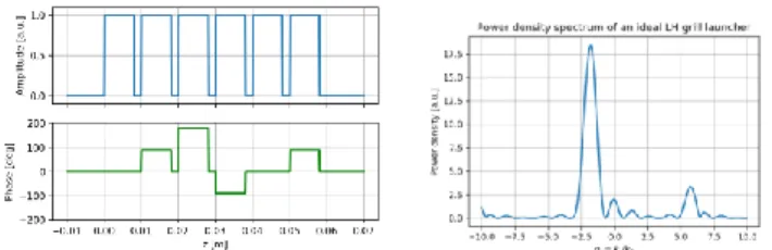
During this hands-on, students have to measure the RF characteristics of a real multijunction mock-up, which was used to validate the LH1 antenna design [14]. First, they have to understand how a multijunction structure achieves to both split and phase shift the RF power (Figure 9). They have to determine analytically and numerically the spectral power density spectrum excited by the antenna (Figure 10). This quantity is an important parameter for the antenna operation and it corresponds to the spatial Fourier transform of the power density at the antenna mouth.
Figure 8. Multijunction hands-on setup and description of its components
This first part is thus the opportunity to discuss and clarify how waves can be described either in spatial and spectral domains. The differences between Fourier transform and Discrete Fourier Transforms are also always discussed, since the latter is used in a Fast Fourier Transform algorithm but not always to the awareness of the students. The direction at which the RF waves should be preferentially launched inside the tokamak plasma, which is related to the usual phased array angle, is also discussed.
Figure 9. Simplified LH antenna: an ideal 4-waveguides phased array radiating power to a plasma medium
Figure 10. Left: Ideal amplitude and phase excitation of the multijunction waveguides. Right: associated power density spectrum.
Then students can perform RF measurements of the prototype multijunction module. However, since this structure uses thin rectangular waveguides (70x8mm), no standard RF components exist for this task. Specific home-made RF loads and couplers have been built to measure a fraction of the power in each waveguide. Students are then guided to the calibration methods required for these probes, using again specific home-made tools such as tapers, reduced size waveguides and matching loads made in graphite (Figure 8).
Once the prototype measurements have been made, the students can compare their results to their antenna model and discuss the importance of measurement uncertainties and the origin of these uncertainties. Finally, the supervisors give the student a movable short-circuit (Figure 8) which can be inserted inside a reduced waveguide. This short is a rough way to model an arc happening inside the waveguide. Students are then asked if it is possible to (i) detect arcs in the multijunction from the analysis of the reflected power and (ii) if it is possible to locate the arcs in the multijunction? They are then left free to do any measurements they wish to give first insights to these questions. During this part are discussed with them the importance of establishing a proper test protocol (What to do? How to it?) and the expected measured values (too much or not enough data?) to analyse an experimental problem.
Ion Cyclotron Resonance Heating hands-on
Two different hands-on related to the ICRH range of frequency (around 50 MHz) have been proposed in the past years to the students. The first one focuses on the voltage measurement apparatus used inside the IC antennas of Tore
Supra/WEST [16]. The second one brings the students to build step by step a low-power mock-up of a representative high-power feeding circuit for the next generation of antenna currently under design for future fusion reactor. These two hands-on are described in the sub-sections below.
Voltage probe Calibration
On the WEST Ion Cyclotron ICRH antennas [17], RF probes are used to measure RF voltages and deduce RF currents [18]. These signals are mandatory in order to monitor the antenna behaviour as well as for its automatic safety interlocks. While providing accurate measurement, these probes have to operate under a severe environment (vacuum and steady-state RF power, which can lead to severe probes heating/arcing if not properly taken into account). Low gain (-80 dB) probes have been manufactured in order to cope with steady-state operations (reduced RF power collected by the probe, thus reduced heat loads). On the other hand, such low gain probes are delicate to calibrate, since their accuracy is hard to predict due to the probe plug cavity ('edge effect'), but also by mechanical discrepancies.
During this hands-on, students have to calibrate such an RF voltage probe. The aim of the calibration of such a probe is to determine the relationship between the voltage in the coaxial line and the voltage got for the probe. In order to perform such a calibration, a home-made calibration setup is provided (Figure 11). This setup mimics the section of a high power coaxial line and the depth of the probe inside its plug can be varied.
Figure 11. RF probe calibration setup.
The calibration setup uses a 30 Ω, 9" coaxial line (internal conductor:
ϕ
ext=140mm; external conductor:ϕ
int=230mm) which is equipped with a probe plug (a DN25 vacuum flange). This choice of 30 Ω lines comes from the fact that this characteristic impedance allows to maximize the peak power handling on our high RF power system. Two impedance transformers30 Ω−50 Ωare used to match the VNA ports. The entire probe has been manufactured at CEA and the detailed drawings are given to the students. The probe copper head is located into or close to the coaxialE-field between inner and outer conductors. The gain of the probe depends on its depth inside its plug as well as the plug geometry. Geometrical discrepancies are present with non-perfect circularity and coaxiality of the inner and outer conductors (1 mm discrepancy has been measured during dimension control), radial distance between inner and outer conductor (due to the whole assembly) and with the probe manufacturing. This hands-on is thus a mean to introduce students the necessity for them to take into account discrepancies and discuss their origins.
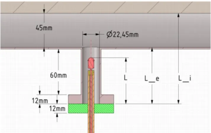
Figure 12. Calibration setup dimensions.
The voltage in the high-power coaxial line is expected to be between 5 kV and 55 kV. The students are then asked to tune the probe depth in order to obtain an output signal from 0 to 10 V, as required for the acquisition system and to deduce the target attenuation of the probe at 60 MHz 5 MHz. For that, they are explained the voltage in a coaxial line, the matching requirements to usual low power coaxial cables in order for them to deduce the optimum dimensions and RF parameters with respect to power handling. The challenge is then to properly calibrate the probe, that is to determine all the gains and losses to deduce the voltage inside the rigid coaxial line.
The electrical equivalent circuit of the calibration setup is illustrated in Figure 13. While usual RF calibration techniques such as TRL could be used to remove the effect of impedance transformers and geometrical adapters [19], they are out of the learning scope of these master students. Instead, we reduce the frequency to 0.3-2.4 MHz in order to reduce transmission line length effects, so that the voltage could be considered comparable at two different points of the line (Figure 14). Thus, assuming that the voltage is uniform in this frequency range, i.e. the probe voltage probe is equal to the open voltage and student can extrapolate the b2/b1 signal from the VNA to deduce the transmission coefficient at 60 MHz.
6 Figure 13. Electrical circuit of the setup.
Figure 14. Electrical circuit of the setup at low frequency.
This hand-on illustrates to the student the difficulty to realize high power RF measurements, especially in Continuous-Wave power operation for which the probe heating and cooling can be a problem. When a very low coupling coefficient is obtained, its value greatly varies with its geometry, in particular, the probe depth. Hence, a precise measurement requires a precise calibration procedure, highlighting the requirements of a precise measurement chain to the students.
Resonant Ring RF Circuit
The second hands-on related with ICRH range of frequency concern the realization of a resonant ring feeder circuit. This circuit is illustrated in Figure 15. The advantage of such a circuit is that when the phase shifters are properly tuned, the power injected in the system (on port 1) gets recirculated and almost no power is reflected or transmitted to port 2. In principle, this feeding scheme could be used to feed an ICRH antenna such as travelling wave antenna for a future fusion reactor [20], in order to improve the power budget of the system. Such a circuit is also load-resilient: changing the attenuator value slightly perturbs the system. In real situation in a high power case, the attenuator corresponds to the travelling wave antenna radiating its power to the plasma. In case of fast change of the plasma and thus of the loading of the antenna, a water-cooled dummy load would be placed at port 2 to dump the power eventually transmitted to.
Figure 15. Equivalent circuit of a resonant ring assembly
Before for the students to assemble and characterize this circuit, they are introduced to RF phase shifters and
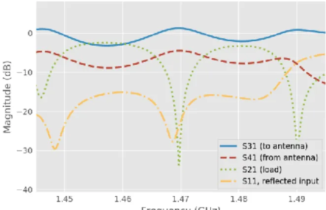
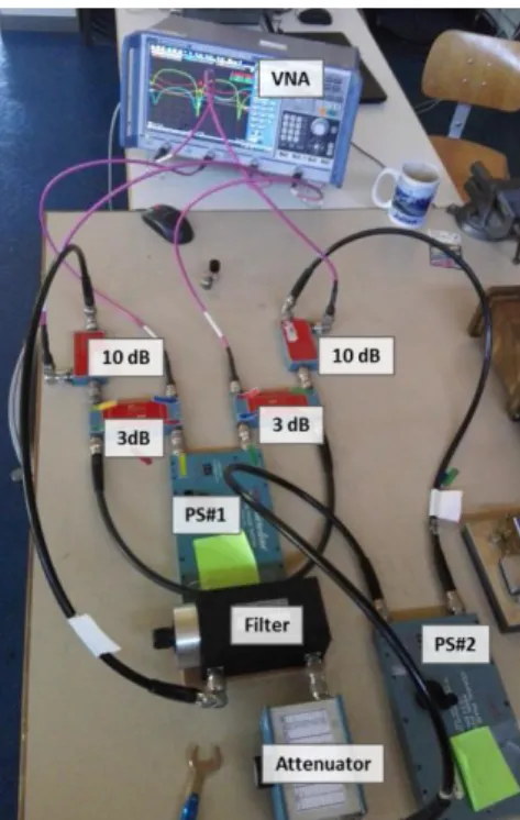
directional couplers, for which they are guided to first deduce from analytical expressions then measure their main figures of merit (Phase shift, Directivity, Isolation and losses). Then they build a variable coupler using two hybrid couplers and a phase shifter (blue dashed in Figure 15). Once done, students are brought to assemble the full resonant ring and to tune it. Although proposed for the ICRH frequency band (30-70 MHz), the circuit can also be built at higher frequencies. The hands-on is performed at 1-2 GHz in order to use reduced size components1. When properly tuned using the two phase-shifters, both the reflected power to port #1 (toward RF source) and the forward power to port #2 tends to zero. Student can verify (from analytical calculations or by direct measurements) that the electrical length of the resonant ring has to be an integer number of 2π [21]. Moreover, adding additional 10 dB directional couplers before and after the “antenna” (simulated by the attenuator in series with the phase shifter) allows monitoring the injected and recirculated power in the resonant ring (Figure 16). If properly tuned, the ratio of the forward power the antenna to the input power is greater than 0 dB, due to the recirculated power in the circuit. Thus, from simple tabletop components (Figure 17), students understand how such a circuit can ensure the integrity of the high power RF generators while minimizing the losses and providing a reliable power feeding network.
Figure 16. Scattering parameters of the (tuned) resonant ring.
1 Narda 3752 coaxial phase shifters and NARDA 3032 coaxial N-connector 3 dB hybrid coupler.
Figure 17. Example of student resonant ring setup. "3 dB" stands for 3 dB hybrid couplers, "10 dB" for 10 dB directional couplers (used as signal probes to properly tune the resonant circuit). “PS” stands for Phase-Shifter. A band-pass filter is added to the setup to better “simulate” a travelling wave antenna section, which is equivalent to a RF band-pass filter [21].
Conclusion
Over the 8 years since we’ve started the RF hands-on, as part of the IRFM master fusion event, we have been pleased to make students discover the tools and subjects related to plasma RF heating and current drive. As none of the students had followed any RF courses during their scholarship, RF theory and measurements are not definitely easy to them. The challenges were thus to create hands-on for which they can perform RF measurements and data analysis, without having to know the typical knowledge of RF engineering. If the RF hand-on topics are not always their first choices, students are still happy to learn new things, in particular that from design to application, many steps pave the road of researchers and that none of them must be neglected.
Acknowledgements
The author would like to thanks the organizers of the Cadarache IRFM master fusion events: Remy Guirlet, Nicolas Fedorzak, Pascale Monier-Garbet, Rémi Douvenot from ENAC/Toulouse, current and former members and PhD students of the IRFM RF group for their various supports in these activities and of course the students themselves.
References
[1] Freidberg J P 2007 Plasma Physics and Fusion Energy vol 1 (Cambridge University Press)
[2] Bucalossi J, Missirlian M, Moreau P, Samaille F, Tsitrone E, Van Houtte D, Batal T, Bourdelle C, Chantant M, Corre Y, Courtois X,
Delpech L, Doceul L, Douai D, Dougnac H, Faïsse F, Fenzi C, Ferlay F, Firdaouss M, Gargiulo L, Garin P, Gil C, Grosman A, Guilhem D, Gunn J, Hernandez C, Keller D, Larroque S, Leroux F, Lipa M, Lotte P, Martinez A, Meyer O, Micolon F, Mollard P, Nardon E, Nouailletas R, Pilia A, Richou M, Salasca S and Travère J M 2014 The WEST project: Testing ITER divertor high heat flux component technology in a steady state tokamak environment Fusion Eng. Des. 89 907–12
[3] Saoutic B, Chatelier M and De Michelis C 2009 Tore Supra: Toward Steady State in a Superconducting Tokamak Fusion Sci. Technol. 56 1079–91
[4] Bucalossi J 2009 The Gigajoule Discharges Fusion Sci. Technol.
56 1366–80
[5] Ekedahl A, Goniche M, Guilhem D, Kazarian F and Peysson Y 2009 Lower Hybrid Current Drive in Tore Supra Fusion Sci. Technol. 56 1150–72
[6] Hillairet J, Achard J, Bae Y S S, Bai X, Balorin C, Baranov Y, Basiuk V, Becoulet A, Belo J, Berger-By G, Bremond S, Castaldo C, Ceccuzzi S, Cesario R, Corbel E, Courtois X, Decker J, Delmas E, Delpech L, Ding X, Douai D, Ekedahl A, Goletto C, Goniche M, Guilhem D, Gunn J P P, Hertout P, Hoang G T, Imbeaux F, Kirov K K K, Litaudon X, Magne R, Mailloux J, Mazon D, Mirizzi F, Mollard P, Moreau P, Oosako T, Petrzilka V, Peysson Y, Poli S, Preynas M, Prou M, Saint-Laurent F, Samaille F, Saoutic B, Sharma P K K, Bécoulet A, Belo J, Berger-By G, Brémond S, Castaldo C, Ceccuzzi S, Cesario R, Corbel E, Courtois X, Decker J, Delmas E, Delpech L, Ding X, Douai D, Ekedahl A, Goletto C, Goniche M, Guilhem D, Gunn J P P, Hertout P, Hoang G T, Imbeaux F, Kirov K K K, Litaudon X, Magne R, Mailloux J, Mazon D, Mirizzi F, Mollard P, Moreau P, Oosako T, Petržílka V A, Peysson Y, Poli S, Preynas M, Prou M, Saint-Laurent F, Samaille F, Saoutic B, Sharma P K K, Becoulet A, Bremond S, Belo J, Berger-By G, Bremond S, Castaldo C, Ceccuzzi S, Cesario R, Corbel E, Courtois X, Decker J, et al 2012 Lower Hybrid antennas for nuclear fusion experiments Antennas and Propagation (EUCAP), 2012 6th European Conference on (IEEE) pp 1–4
[7] Bonoli P T 2014 Review of recent experimental and modeling progress in the lower hybrid range of frequencies at ITER relevant parameters AIP Conference Proceedings vol 21 pp 15–24 [8] Wilson J R and Bonoli P T 2015 Progress on ion cyclotron range
of frequencies heating physics and technology in support of the International Tokamak Experimental Reactor Phys. Plasmas 22 021801
[9] Hillairet J, Mollard P, Zhao Y, Bernard J-M J-M, Song Y, Argouarch A, Berger-By G, Charabot N, Chen G, Chen Z, Colas L, Delaplanche J-M J-M, Dumortier P, Durodié F, Ekedahl A, Fedorczak N, Ferlay F, Goniche M, Hatchressian J-C J-C, Helou W, Jacquot J, Joffrin E, Litaudon X, Lombard G, Maggiora R, Magne R, Milanesio D, Patterlini C C, Prou M, Verger M J-M J-J-M J-J-M, Volpe R, Vulliez K, Wang Y, Winkler K, Yang Q and Yuan S 2015 Ion cyclotron resonance heating systems upgrade toward high power and CW operations in WEST AIP Conf. Proc. 1689, 070005 vol 1689
[10] Ongena J, Messiaen A M, Kazako Y, R.Koch, Ragona R, Bobkov V, Crombé K, Durodié F, Goniche M, Krivska A, Lerche E, Louche F, Lyssoivan A, Vervier M, Eester D Van, Schoor M Van, Wauters T, Wright J and Wukitch S 2016 Recent advances in physics and technology of Ion Cyclotron Resonance Heating in view of future fusion reactors IAEA Conf. Proc.
[11] Thumm M K and Kasparek W 2002 Passive high-power microwave components IEEE Trans. Plasma Sci. 30 755–86 [12] Hillairet J, Achard J, Brun C, Rasio S and Soler B 2012 Design
and testing of a 5 GHz TE 10-TE 30 mode converter mock-up for the lower hybrid antenna proposed for ITER Fusion Eng. Des. 87 275–80
[13] Bibet P, Nguyen T K, Achard J, Berger-By G, Berio S, Goniche M, Rey G and Tonon G 1994 Experimental and Theoretical Results Concerning the Development of the Main RF Components for Nest Tore Supra {LHCD} Antennae Proceeding of the 18th SOFT Conference vol 1
8 Durocher A, Ekedahl A, Froissard P, Garguiolo L, Garampon L, Goniche M, Hertout P, Kazarian F, Lafon D, Portafaix C, Rey G, Samaille F, Surle F and Tonon G 2000 New advanced launcher for lower hybrid current drive on Tore Supra Fusion Eng. Des. 51–52 741–6
[15] Fisch N J 1987 Theory of current drive in plasmas Rev. Mod. Phys. 59 175–234
[16] Colas L, Vulliez K and Basiuk V 2009 Ion Cyclotron Resonant Heating in Tore Supra Fusion Sci. Technol. 56 1173–204 [17] Hillairet J, Mollard P, Zhao Y, Bernard J-M J-M, Song Y,
Argouarch A, Berger-By G, Charabot N, Chen G, Chen Z, Colas L, Delaplanche J-M J-M, Dumortier P, Durodié F, Ekedahl A, Fedorczak N, Ferlay F, Goniche M, Hatchressian J-C J-C, Helou W, Jacquot J, Joffrin E, Litaudon X, Lombard G, Maggiora R, Magne R, Milanesio D, Patterlini C C, Prou M, Verger M J-M J-J-M, Volpe R, Vulliez K, Wang Y, Winkler K, Yang Q and Yuan S 2015 Ion cyclotron resonance heating systems upgrade toward high power and CW operations in WEST AIP Conf. Proc. 1689, 070005 vol 1689
[18] Helou W, Dumortier P, Durodié F, Lombard G and Nicholls K 2016 ITER-like antenna capacitors voltage probes:
Circuit/electromagnetic calculations and calibrations Rev. Sci. Instrum. 87 104705
[19] Rumiantsev A and Ridler N 2008 VNA calibration IEEE Microw. Mag. 9 86–99
[20] Ragona R 2018 A New ICRF Antenna for Future Reactors: The Travelling Wave Array Antenna (Gent University)
[21] Ragona R 2017 ICRF Traveling Wave launcher for fusion devices J. Phys. Conf. Ser. 841 012022
![[PDF] Cours Systèmes d’information et bases de données | Cours informatique](data:image/gif;base64,R0lGODlhAQABAIAAAP///wAAACH5BAEAAAAALAAAAAABAAEAAAICRAEAOw==)