Adaptive Format Conversion Information as Enhancement Data for
the High-definition Television Migration Path
by
James R. Thornbrue
B.S. Electrical Engineering Brigham Young University, 2001
Submitted to the Department of Electrical Engineering and Computer Science in Partial Fulfillment of the Requirements for the Degree of
Master of Science in Electrical Engineering
at the
Massachusetts Institute of Technology
June 2003
© 2003 Massachusetts Institute of Technology All rights reserved
OF TECHNOL.OGY
JUL 0 7 2003
LIBRARIES
Signature of Author... .... ... .. ...
Department of ectrical Engineering and Computer Science April 14, 2003
Certified by... ...
Jae S. Lim Professor of tIectrical Engineering ThesijSupervisor
Accepted by... ... . . ... Smit Arthur C. Smith
Adaptive Format Conversion Information as Enhancement Data for
the High-definition Television Migration Path
by
James R. Thornbrue
Submitted to the Department of Electrical Engineering and Computer Science on April 23, 2003 in partial fulfillment of the requirements for the Degree of Master of Science in Electrical
Engineering
ABSTRACT
Prior research indicates that a scalable video codec based on adaptive format conversion (AFC) information may be ideally suited to meet the demands of the migration path for high-definition television. Most scalable coding schemes use a single format conversion technique and encode residual information in the enhancement layer. Adaptive format conversion is different in that it employs more than one conversion technique. AFC partitions a video sequence into small blocks and selects the format conversion filter with the best performance in each block.
Research shows that the bandwidth required for this type of enhancement information is small, yet the improvement in video quality is significant.
This thesis focuses on the migration from 10801 to 1080P using adaptive deinterlacing. Two main questions are answered. First, how does adaptive format conversion perform when the base
layer video is compressed in a manner typical to high-definition television? It was found that when the interlaced base layer was compressed to 0.3 bpp, the mean base layer PSNR was 32 dB
and the PSNR improvement due to the enhancement layer was as high as 4 dB. Second, what is the optimal tradeoff between base layer and enhancement layer bandwidth? With the total bandwidth fixed at 0.32 bpp, it was found that the optimal bandwidth allocation was about 96% base layer, 4% enhancement layer using fixed, 16x16 pixel partitions. The base and
enhancement layer video at this point were compared to 100% base layer allocation and the best nonadaptive format conversion. While there was usually no visible difference in base layer
quality, the adaptively deinterlaced enhancement layer was generally sharper, with cleaner edges, less flickering, and fewer aliasing artifacts than the best nonadaptive method. Although further research is needed, the results of these experiments support the idea of using adaptive
deinterlacing in the HDTV migration path.
Thesis Supervisor: Jae S. Lim
Dedication
Acknowledgements
I extend gratitude toward Professor Jae Lim for providing the opportunity to work in his group, for guidance, and for financial support. As a student in Two Dimensional Signal and Image
Processing, I was impressed by his teaching. I continue to be motivated by his example.
I also recognize Wade Wan, who helped me get started. His experience and contribution were invaluable. I would like to thank the other members of the Advanced Television Research Program: Brian Heng, Ken Schutte, and especially Cindy LeBlanc. In the largeness that is MIT, their friendship was an oasis.
Thanks to my beautiful wife, Allie, for her patience and support. To my daughter, Marie, and another on the way-you are my inspiration.
1 Introduction. . . . . 1.1 The HDTV Migration Path ...
1.1.1 History of Terrestrial Television Standards ....
1.1.2 The Migration Path to Higher Resolutions ....
1.2 Scalable Video Coding ... 1.2.1 Residual Coding ...
1.2.2 Adaptive Format Conversion ...
1.3 M otivation for Thesis ... 1.3.1 Base Layer Coding ...
1.3.2 Tradeoff Between Base Layer and Enhancement Layer
1.4 Summary ...
1.5 Thesis Overview ...
2 Base Layer Video Coding ...
2.1 MPEG-2 Video Compression ...
2.1.1 Introduction to MPEG ...
2.1.2 Motivation for Video Compression ...
2.1.3 Lossy Compression and PSNR ...
2.1.4 Color Representation and Chrominance Subsampling.
2.1.5 M PEG Layers ...
2.2 Rate Control Strategy for MPEG Encoders ...
2.3 Base Layer Coding for Adaptive Format Conversion ....
2.3.1 Previous Implementation ... 2.3.2 Test Model 5 Video Codec ...
2.3.3 Codec Configuration for Adaptive Deinterlacing ....
2.4 Summary ...
Contents
Bandwidth 15 15 15 18 20 21 23 30 30 31 32 33 35 35 35 38 38 39 40 44 47 47 48 50 503 Adaptive Format Conversion
3.1 Deinterlacing Methods ... 54
3.2 Frame Partitioning ... 58
3.3 Enhancement Layer Coding ... 63
3.4 Summary ... 64
4 R esults. . . . .. . . . . 65
4.1 PSNR Versus Enhancement Layer Bandwidth ... . 65
4.2 Tradeoff Between Base and Enhancement Layer Bandwidth ... .70
4.2.1 Car ... 72 4.2.2 Football. ... 76 4.2.3 Football Still... . 79 4.2.4 Marcie. ... 81 4.2.5 Girl. ... 84 4.2.6 Toy Train... . 89 4.2.7 Tulips Scroll... . 92 4.2.8 Tulips Zoom ... . 96 4.2.9 Picnic ... 98 4.2.10 T raffic . . . .. .. . ... . .. . . . .. . . . 101 4.3 Summary ... 104 5 Conclusion ... 107 5.1 Summary ... 107
5.2 Directions for Future Research ... 109
5.3 Recommendation to Broadcasters ... 114
References ... 115
List of Figures
1.1 A Spatially Scalable Video Codec Based on Residual Coding... .. 22
1.2 A Scalable Codec Based on Adaptive Deinterlacing and Residual Coding... .24
1.3 Adaptive Deinterlacing for the HDTV Migration Path... .. 27
1.4 Adaptive Spatial Upsampling for the HDTV Migration Path... .. 28
1.5 Adaptive Temporal Upsampling for the HDTV Migration Path... .. 29
2.1 Example MPEG GOP Structure with N = 9 and M = 3 ... 43
2.2 Rate Control Strategy for MPEG Encoders ... 46
2.3 TM5 Codec- PSNR Versus Bitrate ... 49
3.1 Deinterlacing Methods ... 57
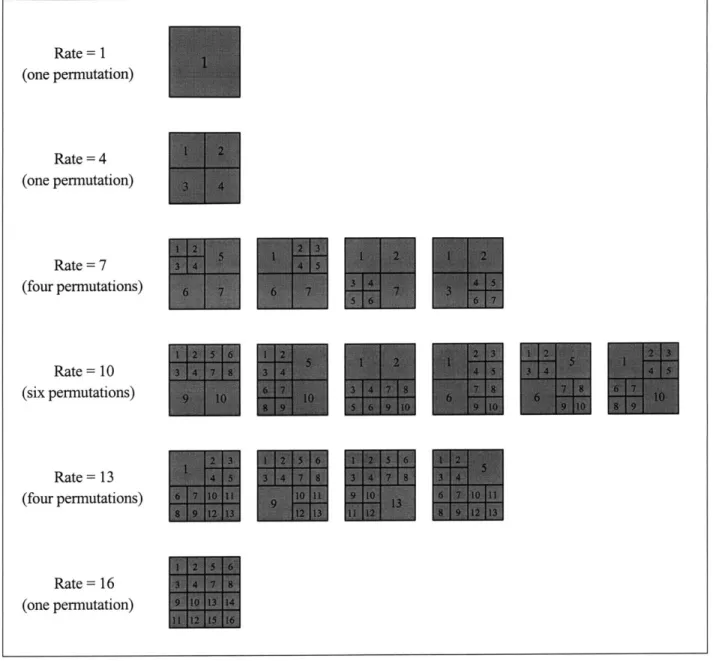
3.2 Seventeen Permutations for Adaptive Frame Partitioning... .. 59
3.3 Example Rate-Distortion Plot for Adaptive Frame Partitioning ... . 62
4.1 First Frame of the Carphone and News Sequences ... 68
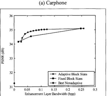
4.2 PSNR Versus Enhancement Layer Bandwidth for Carphone and News... .69
4.3 First Frame of the Car Sequence ... 74
4.4 PSNR Versus Base Layer Allocation for the Car Sequence... .. 75
4.5 First Frame of the Football Sequence ... .. 77
4.6 PSNR Versus Base Layer Allocation for the Football Sequence ... .. 78
4.7 PSNR Versus Base Layer Allocation for the Football Still Sequence ... .80
4.8 First Frame of the Marcie Sequence ... 82
4.9 PSNR Versus Base Layer Allocation for the Marcie Sequence ... .. 83
4.10 First Frame of the Girl Sequence ... . 86
4.11 PSNR Versus Base Layer Allocation for the Girl Sequence ... .. 87
4.12 Aliasing in the Girl Sequence ... 88
4.13 First Frame of the Toy Train Sequence ... .. 90
4.14 PSNR Versus Base Layer Allocation for the Toy Train Sequence ... .91
4.16 PSNR Versus Base Layer Allocation for the Tulips Scroll Sequence ... .94
4.17 Stair-step Discontinuities in the Tulips Scroll Sequence ... . 95
4.18 PSNR Versus Base Layer Allocation for the Tulips Zoom Sequence ... .97
4.19 First Frame of the Picnic Sequence ... 99
4.20 PSNR Versus Base Layer Allocation for the Picnic Sequence ... 100
4.21 First Frame of the Traffic Sequence ... 102
4.22 PSNR Versus Base Layer Allocation for the Traffic Sequence ... .103
4.23 Summary of Optimal Tradeoff Between Base and Enhancement Layer Bandwidth for Ten Video Sequences ... 105
5.1 Migration to 1080P from 10801, 1080P@30fps, and 720P for the Car Sequence... .112
List of Tables
1.1 High-definition Video Formats ...
2.1 Level Definitions for the MPEG-2 Main Profile ...
4.1 List of High-definition Video Test Sequences ...
19 37 71
Chapter
1
Introduction
1.1 The HDTV Migration Path
1.1.1 History of Terrestrial Television Standards
The NTSC (National Television Systems Committee) standard for terrestrial television
broadcasting in the United States was established in 1941, with color added in 1953. NTSC is the analog television standard in North America and Japan. Other conventional television systems used throughout the world include PAL (phase-alternating line) and SECAM (Sequential Couleur a Memoire). These three systems all have similar video, audio, and
transmission quality. For example, NTSC delivers approximately 480 lines of video, where each line contains 420 picture elements (pixels or pels). The spatial resolution is described by the number of lines in the vertical dimension and the number of pixels per line in the horizontal dimension. When snapshots of a scene are refreshed at a sufficiently high rate, the human visual system perceives continuous motion. In a tradeoff between spatial and temporal resolution, NTSC uses interlaced scanning at approximately 60 fields/second. Interlaced scanning (IS) means that every alternate snapshot contains only the even or the odd lines. In interlaced scanning, these snapshots are calledfields.
In 1987, the United States Federal Communication Commission (FCC) established an Advisory Committee on Advanced Television Service (ACATS) consisting of 25 leaders from the
television industry with the purpose of recommending an advanced television system to replace the NTSC standard. Initially, ACATS received 23 proposals, ranging from improved forms of NTSC to completely new high-definition television (HDTV) systems. By 1991, the number of competing proposals had been reduced to six, including four all-digital HDTV systems. After
years of extensive testing and deliberation, the advisory comittee determined that analog technology would no longer be considered. It would not, however, recommend one of the four remaining systems above another because each had different strengths. As a result, ACATS recommended that the individual companies developing these systems be allowed to implement certain improvements that they had proposed. In addition, the advisory committee expressed enthusiasm for a single, joint proposal made of the best elements from each system.
In response to this incitement, the companies representing the four all-digital systems formed the Digital HDTV Grand Alliance in May, 1993. The members of the Grand Alliance were AT&T, General Instrument, North America Phillips, Massachusetts Institute of Technology, Thomson Consumer Electronics, the David Sarnoff Research Center, and Zenith Electronics Corporation. Another important organization at this time was the Advanced Television Systems Committee (ATSC), a private sector group representing all segments of the television industry. The ATSC took responsibility for documenting the specifications for the HDTV standard based on the Grand Alliance system. On December 24, 1996, the FCC adopted the major elements of the ATSC digital television standard [1, 2].
The ATSC standard has many improvements over its analog predecessor. The primary goal of HDTV is to provide increased spatial resolution (or "definition") compared to conventional analog television systems. One example of a high-definition video format has a spatial
resolution of 1080 lines and 1920 pixels per line with interlaced scanning at 60 fields/sec-over ten times the resolution of NTSC. The ATSC standard also supports progressive scanning (PS). Unlike interlaced scanning, where a field contains only the even or odd lines, progressive scanning retains all the lines in each snapshot. A progressively scanned snapshot is called a
frame. Another improvement in HDTV is the aspect ratio (width-to-height) of the display, where
a larger aspect ratio in conjunction with high definition leads to an increased viewing angle and more realistic viewing experience. HDTV has an aspect ratio of 16:9 with square pixels,
compared to 4:3 for NTSC. The HDTV standard includes CD quality surround sound as well as the ability to transmit data channels and interact with computers. It also supports different high-definition video formats. For instance, a program originally captured on film can be transmitted in its native frame rate of 24 frames/sec. Other programs such as sporting events may choose to
trade off spatial resolution for increased temporal resolution, yielding smoother perceived motion. In addition, multiple programs can be sent on the same HDTV channel. The NTSC
standard requires all programs to be converted to the same format before transmission and is limited to one program per channel. Because of digital transmission technology, HDTV receivers are able to reconstruct a "perfect" picture without multipath effects, noise, or interference common to analog television. [3, 4]
The addition of color to the NTSC standard in 1953 was done in a backward-compatible manner so that black-and-white television sets were not made obsolete by the broadcast of color
programs. This was done by adding a small amount of color information where it would not significantly interfere with the black-and-white (luminance) part of the signal. However, when high-definition television was being developed, it was decided that a non-compatible standard was necessary to achieve the desired resolution and quality. This means that current analog television receivers will not be able to decode an HDTV signal. Transmission of NTSC
television is scheduled to be phased out in 2006. By this time, all broadcast television programs will be transmitted in the HDTV format, and consumers will be required to purchase an HDTV receiver in order to watch broadcast television.
The transition to HDTV faces a formidable economic hurdle. At the time of writing, there are an estimated 105 million households in the United States with an average of 2.4 NTSC television sets per household. The average price of an HDTV set is $1,500, and a set-top HDTV converter is roughly $500. Needless to say, the high cost of HDTV technology is discouraging to the individual consumer. Broadcasting equipment must also be replaced. This equipment is
estimated at several million dollars per station, and there are 1,650 high-power television stations in the United States. The total economic impact of this transition is on the order of $200 billion.
In order to avoid transition problems like this in the future, the HDTV standard was designed to allow additional features in a backward-compatible manner. In a high-definition television set, data that is not understood is simply ignored. In this way, information may be added to the signal without interfering with functions that are presently defined. It is this flexibility that will allow the migration path to higher resolution video formats that is considered in this thesis.
1.1.2 The Migration Path to Higher Resolutions
Despite the significant improvements in the high-definition standard, a primary target of HDTV has still not been met-the ability to transmit 1080x 1920 progressively scanned video at 60 frames/sec (1080P) in a single 6-MHz channel. 1080P requires a sample rate of approximately 125 Mpixels/sec, which exceeds the maximum rate of 62.7 Mpixels/sec allowed by the MPEG-2 video compression portion of the HDTV standard. MPEG-2 video compression will be
discussed in detail in chapter 2.
In addition to exceeding the sample rate limit, 1080P cannot be compressed into a single HDTV channel without significant loss of picture quality for difficult scenes. The transmission
technology used for HDTV transmission allows a bandwidth of approximately 19 Mbits/sec for the video portion of the signal. This means that 1080P must be encoded at 0.16 bits per pixel (bpp). Raw video is 24 bpp, meaning that the required compression is approximately 150 to one. In comparison, MPEG-2 can achieve a compression factor of about 70-80 while maintaining an adequate level of picture quality for most programs. Even if the sample rate required for 1080P were allowed, the high level of compression would limit the viability of this format.
A list of high-definition video formats is provided in Table 1.1. The first six formats are supported in the digital television standard and are commonly used by the television industry. For each video format, the table includes the spatial resolution, frame (or field) rate, scanning method, and pixel rate. Because the transmission bandwidth is limited to 20 Mbps, the pixel rates shown in the table illustrate the need for high amounts of compression. The last video format shown in the table, 1080P, exceeds the sample rate limit for MPEG-2. For this reason, 1080P is not an allowable format.
Table 1.1: High-definition Video Formats
The first six high-definition formats shown in the table are permitted in the U.S. HDTV standard and are commonly used in the television industry. Spatial resolution of VxH means V lines of vertical resolution and H pixels of horizontal resolution. The frame/field rate is the number of frames per second for progressive scanning and the number of fields per second for interlaced scanning. Scanning is either interlaced or progressive. The pixel rate, in pixels per second, demonstrates the need for video compression because the bandwidth for video in an HDTV channel is approximately 19 Mbits per second. The last format, 1080P, exceeds the sample rate constraint of MPEG-2 and usually cannot be compressed to 19 Mbps with a sufficient level of picture quality.
Format Name Spatial Resolution Frame/Field Rate Scanning Pixel Rate
720P 720 x 1280 60 frames/sec PS 55.3 Mpixels/sec 720P@30fps 720 x 1280 30 frames/sec PS 27.6 Mpixels/sec 720P@24fps 720 x 1280 24 frames/sec PS 22.1 Mpixels/sec 10801 1080 x 1920 60 fields/sec IS 62.2 Mpixels/sec 1080P@30fps 1080 x 1920 30 frames/sec PS 62.2 Mpixels/sec 1080P@24fps 1080 x 1920 24 frames/sec PS 49.8 Mpixels/sec 1080P 1080x1920 60 frames/sec PS 124.4 Mpixels/sec
The need for resolutions even higher than 1080P, such as 1440x2560 PS at 60 fps or 1080x 1920 PS at 72 fps, has already been predicted. However, in order for any higher-resolution formats to be broadcast, two things must happen: first, the HDTV standard must be evolved to accept higher sample rates; second, more bandwidth must become available. The sample rate problem can be accommodated by using a scalable coding scheme that is backward compatible with current HDTV transmissions-such a solution is presented in this thesis. Additional bandwidth may become available in several ways. Once analog television is phased out, the FCC may allocate more bandwidth for HDTV channels; alternatively, improvements may be made in video compression techniques that free up existing bandwidth. In either case, the increased bandwidth is expected to be small in the near future. How to add support for 1080P and other higher-resolution video formats while dealing with these two issues-backward compatibility and limited bandwidth-is what is known as the migration path problem, or simply the migration
path, for high-definition television.
1.2 Scalable Video Coding
This thesis presents a migration path based on scalable video coding. With the proliferation of video content on the internet, the problem of scalable video coding has received considerable attention. Because of different connection speeds, video on the internet is often available with several levels of quality or resolution, and scalable techniques are used to minimize the total amount of information that must be stored or transmitted. Instead of encoding each different format independently, a scalable scheme encodes a single, independent base layer, and one or more dependent enhancement layers, where each enhancement layer is used to increase the resolution or quality of the previous layer.
For each enhancement, the higher resolution is first provided by a conversion from the base layer format to the enhancement layer format (note that for quality scalability, no format conversion is necessary). Then, residual information is added to improve the picture quality. The residual, or error, is defined as the difference between the interpolated base layer video and the original video sequence. Residual coding is well understood and is used in popular scalable coding
schemes such as the MPEG-2 and MPEG-4 multimedia standards. Another type of enhancement
is adaptiveformat conversion (AFC). Because the encoder has access to the original video
sequence, the conversion to the enhancement layer format can be done adaptively. This is accomplished by breaking the video into small blocks and deciding which of several predefined interpolation methods best reconstructs the original sequence on a block-by-block basis.
Adaptive format conversion is a fairly new area of research. The next two sections discuss residual and AFC coding in more detail.
1.2.1 Residual Coding
As defined above, the residual is the difference between the original video sequence and an interpolated version of the decoded base layer video. Figure 1.1 shows a block diagram of a
spatially scalable video codec (encoder/decoder) using residual information in an enhancement layer. In this example, the base video format is 720P, and the enhanced video format is 1080P. The encoder downsamples the 1080P video sequence to 720x1280 pixels, and the
lower-resolution video is encoded as the base layer bitstream. The encoding process is generally lossy, meaning that the reconstructed video will not be the same as the original video sequence. After
the base layer is reconstructed, it is upsampled to 1080P, and the residual is encoded as an enhancement layer. At the decoder, the base layer bitstream is decoded to produce 720P video. The decoder interpolates this video to 1080x1920 pixels, then adds the residual information to create the enhanced-resolution video, which is 1080P. Note that both the encoder and decoder must decode the base layer bitstream and perform the format conversion in exactly the same way.
A scalable coding scheme such as this, applied to the migration path, is backward compatible. The base layer video format is allowed in the current HDTV standard and is independent of the enhancement layer. Given a large enough enhancement layer bandwidth, residual coding has the ability to generate enhanced video of arbitrarily good quality. Unfortunately, even for low-quality enhancements, the bitrate required for residual data is typically higher than that foreseen in the near future for high-definition television.
Encoder
spatial Base Laye r Base Layer
-onamln -noero Bitstream
Downsmplig Enoder(720P)
Spatial Base Layer
Upsampling Decoder
Residual Enhancement Layer
Encoder Bitstream Decoder Base Layer Bitstream Enhancement Layer Bitstream Base Layer Decoder + +
Base Layer Video
(720P)
Enhancement Layer Video
(IO080P)
Figure 1.1: A Spatially Scalable Video Codec Based on Residual Coding
The original 1080P video is downsampled to 720x 1280 pixels and encoded as the base layer. After it is reconstructed, the base layer video is upsampled to the original format, and the residual, or error, is encoded as the enhancement layer. The decoder uses the base layer bitstream to reconstruct the 720P video. The 1080P enhancement layer video is created by
spatial upsampling and the addition of the residual, which improves the picture quality. Note that this scalable codec is backward compatible with the current HDTV standard.
Original Video
1.2.2 Adaptive Format Conversion
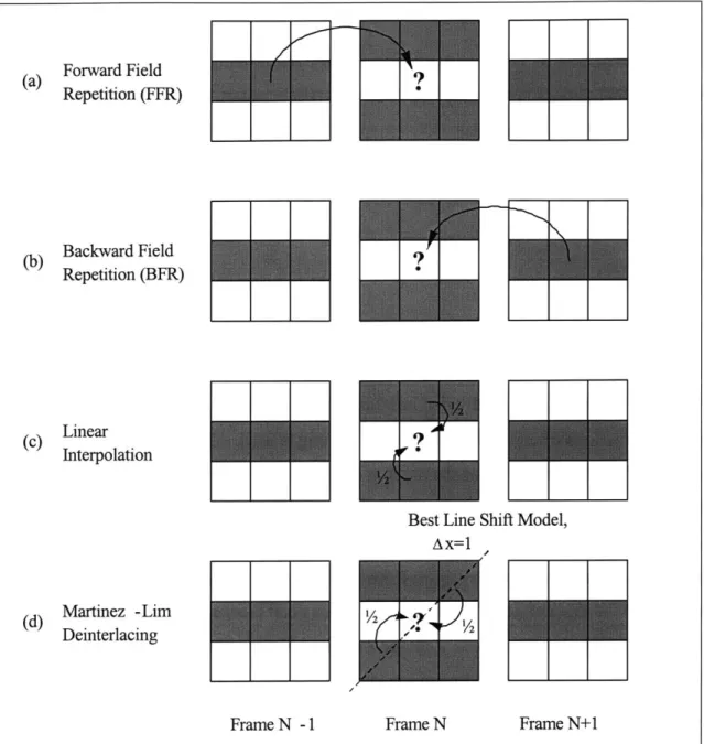
Adaptive format conversion is an alternative, or addition, to residual coding proposed by Sunshine [5, 6] and Wan [7, 8, 9]. In the residual coding example of the previous section, a single format conversion method was used to create the enhanced-resolution video. However, the format conversion can be made even better if more than one technique is used adaptively. Sunshine and Wan look specifically at adaptive deinterlacing by selecting four deinterlacing methods: linear interpolation, Martinez-Lim deinterlacing [10], forward field repetition, and backward field repetition. The encoder partitions the video sequence into nonoverlapping blocks and selects the best deinterlacing method for each block. Information about how the blocks are partitioned and which deinterlacing method is used in each block becomes enhancement data that is sent to the decoder. In addition to the AFC enhancement data, the encoder may also send residual information in a second enhancement layer.
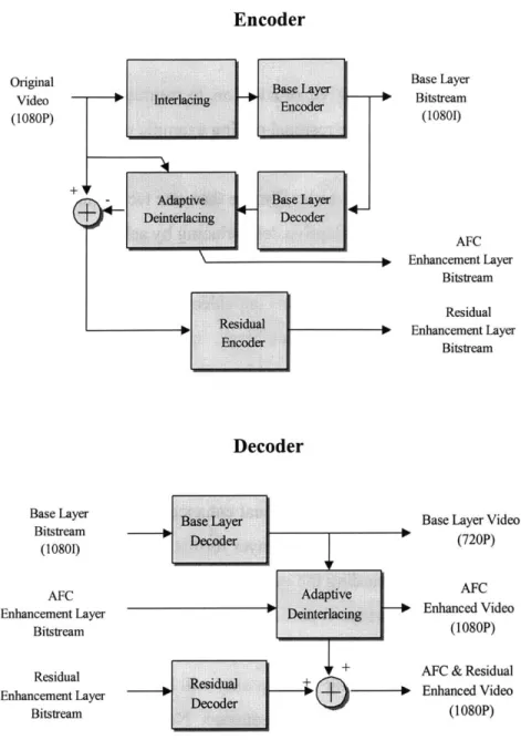
An example video codec with both AFC and residual enhancement is shown in Figure 1.2. The base layer format is 10801, and the enhancement layer format is 1080P. The original 1080P
video sequence is interlaced by discarding the even or odd lines in alternate frames, encoded, then decoded again. The resulting video is partitioned into blocks and the best deinterlacing method is chosen for each block-the partitioning and format conversion information becomes the first enhancement layer. The resulting video quality will be better than if a single
deinterlacing technique were used for the entire sequence. Next, the residual is encoded as the second enhancement layer. At the decoder, the base layer bitstream is decoded to reconstruct the interlaced video sequence. Partitioning and deinterlacing information in the AFC enhancement layer is used to create progressive video, and the residual enhancement layer is used to further improve the quality of the 1080P video sequence.
Original Video
(1080P)
S Interlacing ~uk
+ V Adaptive Base Layer Deinterlacing Decoder rMM" a S Residual i Base Layer Bitstream (10801) AFC Enhancement Layer Bitstream Residual Enhancement Layer Bitstream 1 R esidual __ _+ Decoder Base Layer Bitstream (10801) AFC Enhancement Layer Bitstream Residual Enhancement Layer Bitstream
Base Layer Video
(720P)
AFC -* Enhanced Video
(1080P) AFC & Residual - Enhanced Video
(1080P)
Figure 1.2: A Scalable Codec Based on Adaptive Deinterlacing and Residual Coding The original 1080P video sequence is interlaced by discarding the even or odd lines in each frame, and the resulting video is encoded as the 10801 base layer. The base layer is
reconstructed and compared to the original video sequence in order to find the best deinterlacing method for each partition. Partitioning and deinterlacing information is sent to the decoder as the
first enhancement layer. The residual is encoded as the second enhancement layer. The decoder uses the base layer bitstream to create 10801 video. The partitioning and deinterlacing
information in the first enhancement layer is used to convert the format to 1080P. Finally, the residual information in the second enhancement layer is added to improve the quality of the
1080P video sequence.
Encoder
Decoder
Wan shows that adaptive format conversion provides substantial improvement over the best nonadaptive method and requires lower bitrates than residual coding. However, unlike residual
coding, the ability of adaptive format conversion to exactly reproduce the original video sequence is bound by the performance of the individual format conversion methods. In other words, using adaptive format conversion information alone cannot achieve an arbitrarily high
quality reproduction of the original video sequence, no matter how much bandwidth is allocated to the enhancement layer bitstream.
Despite the above limitation, but because of the low bitrate requirement, adaptive format conversion is a natural choice in the migration to higher-resolution HDTV. For instance, the target format of 1080P can be reached in several ways by adding only a low bitrate AFC enhancement layer to one of the common HDTV formats in table 1.1. The example described above shows how a 10801 base layer and adaptive deinterlacing information is used to produce
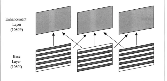
1080P video. This type of enhancement is illustrated in figure 1.3, which shows how the
information in the base layer fields is used create the progressive enhancement layer frames. The use of adaptive deinterlacing in the migration to 1080P is the focus of this thesis.
Another common base layer format is 720P. In the migration to 1080P, a codec that uses adaptive format conversion would select the best spatial interpolation technique for each section of video. There are many different spatial interpolation filters that could be used, including nearest neighbor, bilinear interpolation, bicubic interpolation, and two dimensional transform techniques. An illustration of spatial scalability for the HDTV migration path is provided in figure 1.4.
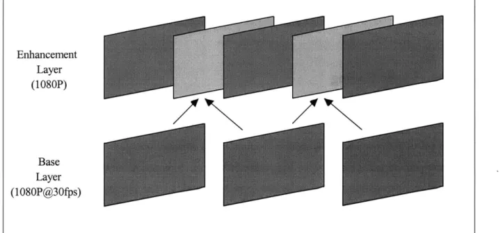
Finally, the base layer format could be 1080P@30 fps, in which case the AFC enhancement layer would contain information about temporal upsampling techniques. These techniques could include forward frame repetition, backward frame repetition, linear interpolation, or motion compensated linear interpolation. Figure 1.5 shows how the information in a 1080P@30fps base layer is used to create a 1080P enhancement layer in this example of adaptive temporal
The three base layer formats discussed above (10801, 720P, and 1080P@30fps) are permitted in the current HDTV standard; therefore, HDTV receivers that do not support the enhancement layer would still be able to decode the base layer video in a backward-compatible manner. Next generation HDTV receivers, on the other hand, would exploit the information in the AFC
enhancement layer bitstream to increase the video resolution to 1080P.
Using adaptive format conversion information in the migration to 1080P would be the initial step in the migration path. In the near future, when the available bandwidth is small, adaptive format conversion would provide video scalability at low enhancement layer bitrates. As more
bandwidth becomes available, the migration path could be extended by adding a residual
enhancement layer to improve the video quality or by further increasing the resolution to formats like 1440P or 1080P@72fps. Previous research has shown that when the base layer is encoded well, the use of adaptive format conversion in conjunction with residual coding is more efficient than residual encoding alone.
Figure 1.3: Adaptive Deinterlacing for the HDTV Migration Path
This figure illustrates how a 10801 base layer is used to create a 1080P enhancement layer. The arrows indicate the base layer fields that are used to create the progressive enhancement layer frames. Enhancement Layer .~ i2 (I1080P) .- ~ Base Layer (10801)
Figure 1.4: Adaptive Spatial Upsampling for the HDTV Migration Path
This figure illustrates how a 720P base layer is used to create a 1080P enhancement layer. The resolution of each frame is increased adaptively using a number of spatial interpolation techniques. Enhancement Layer (1080P) Base Layer (720P)
Figure 1.5: Adaptive Temporal Upsampling for the HDTV Migration Path
This figure illustrates how a 1080P@30fps base layer is used to create a 1080P enhancement layer. The arrow indicate the base layer frames that are used to extrapolate the missing enhancement layer frames.
Enhancement Layer (1080P) Base Layer (1080P@30fps)
1.3 Motivation for Thesis
Current research into adaptive format conversion has encouraging implications in the migration to higher resolution HDTV. One such proof of concept is that an AFC enhancement layer requires a very small bandwidth. However, there are still many issues specific to the migration path that have not been addressed. These include the coding of the base layer video and the
optimal allocation of base and enhancement layer bandwidth in a fixed bandwidth environment. These two issues are introduced in the following sections as the fundamental motivation for this thesis.
1.3.1 Base Layer Coding
When Sunshine introduced the idea of an AFC enhancement layer, he measured the
improvement in picture quality that comes from different enhancement layer bandwidths. These results were created using an uncoded base layer bitstream. In practice, however, an HDTV bitstream is encoded with a marked reduction in picture quality. The improvement in video quality derived from an uncoded base layer can be thought of as an empirical upper bound on the performance of AFC as enhancement data.
Wan extended the analysis to include encoded base layers of various qualities. Like Sunshine, he measured the improvement in video quality as a function of enhancement layer bandwidth-not just for an uncoded base layer but for many levels of base layer degredation. Not
surprisingly, the quality of the reconstructed video using AFC enhancement data was an increasing function of base layer quality. Furthermore, when the base layer was coded poorly, residual coding outperformed AFC for higher enhancement layer bitrates. Wan concluded that the decision to use AFC, residual coding, or a combination of the two is a function of both base layer quality and enhancement layer bandwidth and is not always obvious. He also concluded that because it requires such a small bandwidth, the use of adaptive format conversion seems ideally suited for the HDTV migration path.
In the work cited above, no attempt was made to determine what level of base layer quality is typical to the compression of HDTV video sequences. In practice, different video encoders have varying levels of performance (higher performance means an encoder generates better quality video for the same amount of compression). Wan avoided the issue of encoder implementation by using a nonstandard encoding strategy and by using base layer quality (rather than bandwidth) as the independent variable. A side effect of this approach is that the results do not show how AFC enhancement performs in the specific context of the HDTV migration path. In order to fit into a 19 Mbps bandwidth, for example, 10801 is encoded at approximately 0.3 bits per pixel-a compression factor of about 80 to 1. Depending on the encoder implementation, the resulting video quality may vary considerably. It is uncertain from previous results what kind of quality can be expected from this level of compression and whether adaptive format conversion will improve the video quality in any significant way. This leads to the first motivation for this thesis:
Motivation #1: How does adaptive format conversion perform when the base layer video is
compressed in a manner typical to high-definition television?
In order to answer this question, the implementation presented in this thesis uses a standard HDTV encoding strategy. With this encoder, the video quality is determined by the base layer bandwidth, and it is possible to determine where HDTV falls in the spectrum of previous results.
1.3.2 Tradeoff Between Base Layer and Enhancement Layer Bandwidth
In a fixed bandwidth environment such as HDTV, it is important to discuss the tradeoff between the base layer and enhancement layer. For example, if the total bandwidth (base plus
enhancement) is fixed at 0.32 bits per pixel, how much should be allocated to the base layer and how much to the enhancement layer? The answer to this question depends on two factors:
1. How much is the base layer degraded?
When part of the total bandwidth is allocated to the enhancement layer, the base layer video will be degraded to some degree. The integrity of the base layer is important because not all
receivers will be equipped to use the enhancement layer information. If the base layer degradation is severe, then no amount of improvement in the enhancement layer is worth the cost. On the other hand, a small enhancement layer bandwidth may be viable if it does not significantly affect the base video quality but provides substantial improvement to the enhanced resolution video. This question is the second motivation for this thesis:
Motivation #2: What is the optimal tradeoff between base layer and enhancement layer bandwidth?
1.4 Summary
Previous research suggests that a scalable video codec based on adaptive format conversion information may be an ideal solution to the migration path for high-definition television. The first section of this chapter introduced the migration path problem. It began with a brief history of terrestrial television standards in the United States, highlighting the advantages of the high-definition standard over the current analog system. Even with these improvements, however, there are still limitations on the transmittable video resolution, and the need to transmit higher resolution formats in the future has already been recognized. In particular, 1080P is a desirable format that is not permitted in the current U.S. HDTV standard. The question of how to add support for 1080P and other, higher-resolution formats in a way that is backward compatible with the current HDTV standard is known as the migration path problem.
Section 1.2 introduced the concept of scalable video coding as a solution to the HDTV migration path. Residual and adaptive format conversion information are two types of enhancement
information that can be added on top of a compatible base layer. It was shown that 10801, 720P, and 1080P@30fps are all compatible base layer formats that can be used in the migration to 1080P. The use of adaptive deinterlacing information in the migration from 10801 to 1080P is the focus of this thesis.
Adaptive format conversion has been studied before in the general context of multicast video coding. The results prove the concept of using an AFC enhancement layer in many scalable coding scenarios, but the implementation ignores two issues specific to the HDTV migration path: the coding of the base layer video and the optimal allocation of base and enhancement layer bandwidth. These limitations are restated below as the fundamental motivation for this thesis:
Motivation #1: How does adaptive format conversion perform when the base layer video is
compressed in a manner typical to high-definition television?
Motivation #2: What is the optimal tradeoff between base layer and enhancement layer
bandwidth?
1.5 Thesis Overview
The next chapter gives an introduction to MPEG-2 and video coding terminology that is used throughout the thesis. MPEG-2 is the video compression algorithm used in the U.S. HDTV standard. The main difference between this and previous work is the base layer codec. In this thesis, motion compensation and rate control are used to encode the base layer video in a way that is typical to HDTV.
Chapter three provides a detailed description of the adaptive format conversion enhancement layer, including the four deinterlacing techniques, fixed and adaptive frame partitioning schemes, optimal parameter selection, and parameter coding. The implementation of adaptive
deinterlacing that is used in this thesis has been studied previously and is reviewed here for convenience.
The results of two main experiments are found in chapter four. In the first experiment, the base layer video is encoded like HDTV, and the quality of the enhancement layer video is measured as a function of enhancement layer bandwidth. It is determined how these results compare to previous work. In the second experiment, the total bandwidth is fixed and divided between the
base and enhancement layer in order to discover the optimal tradeoff. The experiment is performed for ten video sequences with different characteristics.
Chapter 2
Base Layer Video Coding
MPEG-2 is the video compression algorithm used in the U.S. HDTV standard. This chapter provides an introduction to MPEG, its structure, and the techniques that are used to achieve high
levels of compression with relatively little loss in picture quality. MPEG gives an encoder a great deal of flexibility, and an encoding strategy for constant bitrate applications such as HDTV is explained. With this background in mind, the first motivating question for this thesis is revisited: how does adaptive format conversion perform when the base layer is compressed in a
manner typical to HDTV? It is noted that the previous implementation used a base layer coding
strategy that cannot answer this question. The final section of this chapter introduces the MPEG-2 encoder that is used in the current work, along with its performance characteristics.
2.1 MPEG-2 Video Compression
2.1.1 Introduction to MPEG
The Moving Picture Experts Group (MPEG) was formed in 1988 in response to a growing need for audio and video compression standards across many diverse industries. MPEG is formally called ISO/IEC JTC1/SC29/WG 1I within the International Standards Organization (ISO) and the International Electrotechnical Commission (IEC). Their efforts soon produced the highly
popular MPEG-I multimedia standard. MPEG-I is intended for bitrates around 1.5 Mbps, such as CD-ROMs and digital video recorders. Even before MPEG-I was complete, work began on MPEG-2, which is designed for larger picture sizes and higher bandwidth applications such as HDTV and DVD (Digital Versatile Disk). MPEG-2 also includes support for interlaced scanning and video scalability that was not part of MPEG-1. Another standard, MPEG-4, is
currently being developed. Originally intended for very low bitrate applications such as video telephones, it has also come to include support for irregular shaped video objects, content-based manipulation, and editing. Widely accepted video compression standards such as MPEG-1 and MPEG-2 have reduced the cost and risk involved with deploying new technology.
MPEG-2 contains a large set of video compression tools, including different color sampling formats, frame prediction types, and scalability options. Because not all applications require the complete set of tools, MPEG-2 is divided into profiles that contain various subsets of the video compression techniques. The five MPEG-2 profiles are simple, main, SNR scalable, spatially
scalable, and high. MPEG-2 is also divided into levels that constrain the maximum spatial resolution, frame rate, sample rate, and bitrate for each profile. The four levels are low, main, high-1440, and high. Table 2.1 describes the level definitions for the main profile of MPEG-2. The video compression portion of the ACATS standard for high-definition television uses the MPEG-2 main profile at high level (MP@HL). Allowable video formats for HDTV are limited by the maximum values shown in the table.
The remainder of this chapter introduces the MPEG-2 main profile. Some excellent references are provided for a more general discussion of video compression [11], an overview of MPEG [12, 13, 14], and the MPEG standard documents [15, 16, 17].
Table 2.1: Level Definitions for the MPEG-2 Main Profile
The video portion of the ACATS high-definition television standard uses the MPEG-2 main profile at high level (MP@HL). Permissible video formats for HDTV are limited by the MP@HL spatial resolution, frame rate, sample rate, and bitrate constraints. The video coding techniques used in the MPEG-2 main profile are introduced in this chapter.
Level Parameter Maximum Value
spatial resolution 11 52x 1920 pixels
High frame rate 60 fps
(MP@HL) sample rate 62,668,800 samples/sec
bitrate 80 Mbps
spatial resolution 1152x1440 pixels
High-1440 frame rate 60 fps
(MP@H-14) sample rate 47,001,600 samples/sec
bitrate 60 Mbps
spatial resolution 576x720 pixels
Main frame rate 30 fps
(MP@ML) sample rate 10,368,000 samples/sec
bitrate 15 Mbps
spatial resolution 288x352 pixels
Low frame rate 30 fps
(MP@LL) sample rate 3,041,280 samples/sec
2.1.2 Motivation for Video Compression
Video is a sequence of rectangular frames of the same size, displayed at a fixed rate. Each frame is represented by an array of pixels where the number of pixels determines the resolution (or definition) of the frame. The individual pixels are comprised of three color components-for raw video, each color is represented digitally by 8 bits. For example, when the 1080P format is uncompressed, it requires a bitrate of
pies frames bits colors
1080 x 1920 x 60 f 8 b 3 2,848 Mbps. (2.1)
frame sec color pixel
In comparison, the bandwidth available for video transmission in an HDTV channel is only about 19 Mbps-it is impossible to transmit raw, high-definition video with this technology.
Fortunately, a typical video sequences has a large amount of redundant information. Within a single frame, pixels tend to be similar to those that surround them; between frames, pictures are similar to the frames that precede and follow them. Video compression techniques take
advantage of these redundancies to reduce the amount of information necessary to describe a complete video sequence. Further reduction is possible because of characteristics of human perception. The human visual system is less sensitive to detail in moving objects. It is also less
sensitive to detail in certain color characteristics. As much as possible, the redundant and
irrelevant information in a video sequence are eliminated in order to compress raw video to more manageable bitrates.
2.1.3 Lossy Compression and PSNR
There are two types of compression: lossless and lossy. Lossless compression results in perfect picture reconstruction, yet there is a limit on the amount of data reduction that is possible using lossless techniques. Lossy compression, on the other hand, is generally able to achieve much higher levels of compression. The tradeoff is that the reconstructed picture is not exactly the
compression algorithm where the lost information is often undetectable or does not significantly detract from the picture quality.
With lossy compression, or whenever there is picture degradation, it is useful to have a quantitative measure of video quality. One such measure is the peak signal-to-noise ratio (PSNR), defined here:
PSNR = 10 log 2552 (2.2)
MSE'
where 255 is the peak pixel value and MSE is the mean squared error of the luminance pixels. It is important to point out that no single measurement can encompass all characteristics of the video degradation; however, PSNR is widely used in the field and is useful as a rough indicator of video quality. In this thesis, PSNR will be used to plot results and to recognize general trends
(i.e. the video quality is getting better or worse). However, the final test will always be visual inspection. Where it is instructive, the measured PSNR will be accompanied by a written
description of the compression artifacts.
2.1.4 Color Representation and Chrominance Subsampling
The human eye detects different amounts of red, green, and blue light, and combines them to form the various colors. For this reason, video capture and display devices typically use the RGB (Red, Green, Blue) color space. Another way to represent color information is the YUV color space. YUV is related to RGB by the following matrix equation:
Y 0.2990 0.5870 0.1140 R
U -0.1687 -0.3313 0.5000 G (2.3)
The Y component represents the luminance (brightness) of a color. The U and V components represent the hue and saturation, respectively, and together are the two chrominance
components. The advantage of separating the luminance and chrominance is that they can be processed independently. The human visual system is more sensitive to high frequency variation in the luminance component, and insensitive to high frequency variation in the two chrominance components. This characteristic is exploited by subsampling the chrominance information. MPEG defines the following chroma sampling formats: when the full chrominance components are used it is called 4:4:4; when the chrominance components are subsampled by two in the vertical dimension it is called 4:2:2, and when the chrominance components are subsampled by two in the vertical and horizontal dimensions it is called 4:2:0. The 4:2:0 chroma format reduces the total amount of information by 50%, and the loss is largely imperceptible. For this reason, the MPEG-2 main profile uses 4:2:0 chroma sampling.
2.1.5 MPEG Layers
MPEG divides the video sequence into various layers: from the smallest to the largest, these layers are block, macroblock, picture, group of pictures, and video sequence. The individual layers are described in the remainder of this section, including the techniques that allow MPEG to exploit redundant and irrelevant information and achieve high levels of compression.
On the smallest scale, MPEG divides each picture into non-overlapping 8x8 pixel squares, called blocks, which form the basic building block of an MPEG video sequence. Spatial redundancy is exploited on the block level by transforming the pixel information to frequency information using the discrete cosine transform (DCT). The DCT transforms the 64 pixel intensities into 64 coefficients which, when multiplied by 64 orthonormal basis functions, sum to form the original picture. For typical blocks, the DCT concentrates most of the energy into a relatively small number of the lower-frequency coefficients. After the DCT operation, the coefficients are quantized by dividing by a nonzero positive integer (called a quantization value, or quantizer) and discarding the remainder. Quantization is the lossy part of MPEG video compression. The human visual system is more sensitive to low frequency variations, meaning that the
higher-frequency DCT coefficients can be represented with less precision without perceptible loss in image quality. As a result of the DCT and quantization, many of the coefficients will have a value of zero. The coefficients are encoded in order from low to high frequency, and runs of zero coefficients are grouped together with the subsequent nonzero value in a process called
run-level coding. Finally, the distinct run-run-level events-different length strings of zeros followed by
a nonzero value-are each assigned a unique, variable-length code word (Huffman code) depending on the probability of the event occurring. For example, events that are most likely to occur are given the shortest code words, while less likely events are given longer code words. Huffiman codes are an example of entropy coding. Together, the discrete cosine transform, quantization, run-length coding, and entropy coding greatly reduce the amount of information required to represent the picture in a single, 8x8 pixel block.
A macroblock is a group of four blocks from the luminance component (a 16x 16 pixel square) and one corresponding block from each of the two chrominance components. Temporal redundancy is exploited on the macroblock level through motion compensation. Because adjacent pictures are often similar, an estimate can be made by finding a similar 16x16 pixel region in one or two nearby pictures. Instead of encoding all the information in the macroblock, only the difference between the macroblock and its estimate is encoded. If the estimate is good, then the individual blocks that make up the macroblock will be encoded with very few bits. A macroblock that uses motion compensation is called inter-coded. Every inter-coded macroblock is accompanied by one or two motion vectors that indicate the location of the estimate in the neighboring reference pictures. A macroblock that does not use motion compensation is called
intra-coded.
MPEG defines three different kinds of pictures: I, P, and B. A picture where every macroblock is intra-coded is called an I-picture. Predictive pictures (P-pictures) are encoded using motion compensation from a prior I- or P-picture. In a P-picture, a single motion vector accompanies each inter-coded macroblock; however, individual macroblocks may instead be intra-coded. Finally, bidirectionally-predictive pictures (B-pictures) are encoded using motion compensation from one prior and one subsequent I- or P-picture. A macroblock in a B-picture may be intra-coded, or reference one or two other pictures. B-pictures are never used to predict other pictures.
A group of consecutive pictures in MPEG is called a group ofpictures (GOP). The first picture in a GOP is always an I-picture. The rest of the GOP structure is defined by the two parameters N and M: N is the total number of pictures in the GOP, and M is the distance between the I-picture and the first P-I-picture and between two successive P-I-pictures. An example GOP
structure with N = 9 and M = 3 is shown in figure 2.1. The arrows between pictures in the figure
indicate the reference pictures that are used for motion compensation. The individual GOP structure is repeated to make up the entire video sequence.
KS>_
One GOP
Figure 2.1: Example MPEG GOP Structure With N = 9 and M = 3
The first picture in a GOP is an I-picture. The parameter N indicates the total number of pictures in the GOP; M is the distance between the I-picture and the first P-picture and between
consecutive P-pictures. The arrows indicate the reference pictures that are used for motion compensation.
2.2
Rate Control Strategy for MPEG Encoders
Encoding and decoding an MPEG bitstream is highly asymmetric in terms of complexity and computation. For example, the encoder must find motion vectors and decide what quantization values to use-the decoder simply does what it is told to do. The MPEG standard does not specify how an encoder should carry out these tasks; instead, it specifies the syntax that a compliant bitstream must follow. As a result, there is a great deal of flexibility in how a particular video sequence is encoded.
The optimal encoding strategy often depends on the target application and even the video content itself. For example, "live" or "real-time" video must be encoded very quickly, and a narrow, limited search for motion vectors is often used. In addition, the encoder is not able to "look ahead" to find troublesome scenes that may require more bandwidth. In contrast, encoding a movie for a DVD requires the best quality video with no real time constraint. In this case, a full search for the best motion vectors is well worth the time. The encoder is also able to take bandwidth from easily encoded scenes and use it during more difficult scenes. In order to find
where these tradeoffs should occur, the entire video sequence is often processed two or more times.
Constant bitrate applications such as HDTV are encoded using the rate control strategy shown in figure 2.2. The transmission channel is preceded by an encoder buffer and followed by a
decoder buffer; the purpose of the buffers is to absorb instantaneous variations in the bitrate. Data is transferred between the two buffers at a constant bitrate over the transmission channel, but added and removed at a variable bitrate by the encoder and decoder. The encoder is
responsible for protecting against buffer overflow and underflow, and it does so primarily by changing the quantizer scalefactor. As mentioned previously, quantization allows the DCT coefficients to be represented with various levels of precision. MPEG defines a quantizer scale factor,
Q,
in the range {1, 2, 3, ... , 31} that may be changed on the macroblock level.Increasing
Q
tends to decrease the instantaneous encoder output, while decreasingQ
has the converse effect. The encoder monitors the buffer fullness and changesQ
appropriately when the buffer levels are too high or too low. The strategy for choosing the appropriate quantizer scalefactor may be a simple function of buffer fullness, or it may also involve looking ahead at the video content to see how many bits will be actually required (note that for "live" or "real-time"
encoding, the encoder cannot look ahead). In either case, a good encoder will attempt to maximize the video quality while providing a constant stream of data to the transmission channel.
Input Video - Eoder F r B 0 D Output Video
Encoder Buffer Decoder Buffer
Fullness Fullness
Figure 2.2: Rate Control Strategy for MPEG Encoders
The transmission channel is surrounded by an encoder buffer and decoder buffer whose purpose is to absorb instantaneous variation in the bitrate. The encoder protects against buffer overflow or underflow by changing the quantizer scale factor,
Q.
Using a larger value ofQ
results in smaller instantaneous bandwidth because the DCT coefficients are represented with less precision, and vice versa. The strategy for choosing the quantizer scale factor may be a simple function of buffer fullness or a more complicated decision involving the video content.2.3 Base Layer Coding for Adaptive Format Conversion
With the understanding of MPEG-2 video compression developed in this chapter, it is possible to revisit the first motivation for this thesis in more detail-namely, understanding how adaptive format conversion performs when the base layer video is compressed in a manner typical to HDTV. This section begins by describing how different quality base layers were created in the previous implementation and points out that it not the strategy used to encode HDTV. In order to relate the current results to the migration path, a video codec is used that implements a practical encoding approach. The encoder that is used in this thesis (Test Model 5) is described,
including its performance characteristics. The last section of this chapter describes how the base layer video is encoded for the experiments in this thesis.
2.3.1 Previous Implementation
As formerly mentioned, Wan's objective was to determine how an encoded base layer influenced the performance of an AFC enhancement layer. The results were given as a function of base layer quality. In this previous implementation, the base layer was encoded using all I-pictures, and the quantizer scale factor,
Q,
was a single, fixed value. As a result, no motion compensation was used, nor was the bitrate constant. The various base layer qualities were created bychanging the quantizer scale factor. The motivation behind this encoding strategy was that it resulted in equal distortion within each picture and from picture to picture--one drawback was that the base layer bandwidth had no meaningful value. In HDTV, video quality is determined by the channel bandwidth, not artificially controlled in this way. Although the domain of previous experiments certainly includes the level of video quality that is expected for HDTV, it is impossible to determine from this work alone exactly how AFC performs for typical HDTV bitstreams.
2.3.2 Test Model
5
Video Codec
The MPEG-2 codec that is used in the current implementation is the MPEG Software Simulation Group's Test Model 5 Video Codec (TM5) [18, 19]. The codec was developed during the collaboration phase of MPEG-2 in order to determine the merit of proposed compression techniques and resolve ambiguities in what became the official MPEG-2 standard. For this thesis, TM5 was chosen for its numerous advantages. First, the codec is free and open-source. It is also well documented, easy to configure, performs full, half-pel accuracy motion vector
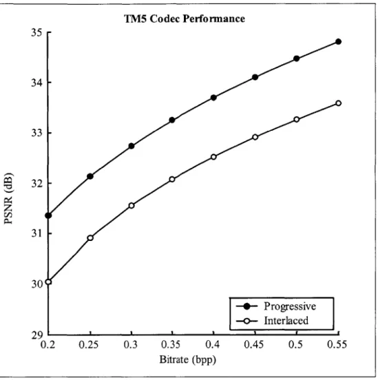
searches, and uses the buffered rate control strategy discussed previously (the quantizer scale factor is a function of buffer fullness only). Finally, TM5 has relatively good performance for the compression levels of interest. Figure 2.3 shows the PSNR of compressed bitstreams as a function of the bitrate (measured in bits per pixel) for the TM5 codec. The 10801 format, for example, is normally encoded at approximately 0.3 bpp, and at this bitrate TM5 yields an average video quality between 31 and 32 dB. Visual inspection of the compressed video sequence reveals a small amount of ringing or blurring in detailed areas such as text and sharp edges. Although these compression artifacts are noticeable, their level seems consistent with actual broadcast HDTV. Notice that the compression of progressive video is more efficient than interlaced video (this is generally true for any MPEG encoder). Figure 2.3 was created by
averaging the results for ten different high-definition video sequences.
Using an encoder such as TM5 means that the results of this thesis are tied to a specific encoder technology; in other words, the generality of previous work is lost. However, because the TM5 encoder has a reasonable level of performance, the results are useful in evaluating the proposed migration path. Prior research shows that the quality of AFC enhanced video improves with
increasing base layer quality, so that when video compression technology improves in the future, AFC enhancement information will be even more beneficial than reported in this thesis.
Figure 2.3: TM5 Codec-PSNR Versus Bitrate
In this figure, the PSNR of progressive and interlaced video is measured as a function of bitrate for the TM5 video codec. The standard HDTV format 10801 is encoded at approximately 0.3 bpp. At this bitrate, TM5 yields a compressed video quality (PSNR) between 31 and 32 dB.
Visually, the compression artifacts from TM5 seem consistent with actual broadcast HDTV. TM5 Codec Performance 35 34 33 32 -31 30' - Progressive -<-Interlaced 29 0.2 0.25 0.3 0.35 0.4 0.45 0.5 0.55 Bitrate (bpp)