HAL Id: hal-01579425
https://hal.inria.fr/hal-01579425
Submitted on 31 Aug 2017
HAL is a multi-disciplinary open access
archive for the deposit and dissemination of
sci-entific research documents, whether they are
pub-lished or not. The documents may come from
teaching and research institutions in France or
abroad, or from public or private research centers.
L’archive ouverte pluridisciplinaire HAL, est
destinée au dépôt et à la diffusion de documents
scientifiques de niveau recherche, publiés ou non,
émanant des établissements d’enseignement et de
recherche français ou étrangers, des laboratoires
publics ou privés.
Dynamically Distributed Network Control for Message
Dissemination in ITS
Anuj Kaul, Katia Obraczka, Mateus Santos, Christian Rothenberg, Thierry
Turletti
To cite this version:
Anuj Kaul, Katia Obraczka, Mateus Santos, Christian Rothenberg, Thierry Turletti. Dynamically
Distributed Network Control for Message Dissemination in ITS. IEEE/ACM DS-RT 2017 - 21st
Inter-national Symposium on Distributed Simulation and Real Time Applications, Oct 2017, Rome, Italy.
�hal-01579425�
Dynamically Distributed Network Control for
Message Dissemination in ITS
Anuj Kaul, Katia Obraczka
UC Santa Cruz {anujkaul,katia}@soe.ucsc.edu
Mateus A. S. Santos, Christian E. Rothenberg
University of Campinas, Brazil {msantos,chesteve}@dca.fee.unicamp.br
Thierry Turletti
Universit´e Cˆote d’Azur, Inria [email protected]
Abstract—We propose D2-ITS, a flexible and extensible frame-work to dynamically distribute netframe-work control to enable message dissemination in Intelligent Transport Systems (ITS). By decou-pling the control- from the data plane, D2-ITS leverages network programmability to address ITS scalability, delay intolerance and decentralization. It uses a distributed control plane based on a hierarchy of controllers that can dynamically adjust to environment- and network conditions in order to satisfy ITS application requirements. We demonstrate the benefits of D2-ITS through a proof-of-concept prototype using the ns-3 simulation platform. Results indicate lower message delivery latency with minimal additional overhead.
I. INTRODUCTION
Vehicular communication is expected to support Intelligent Transport Systems (ITS)1, in which vehicles exchange in-formation to self-drive, coordinate traffic flow, communicate road conditions, avoid accidents, etc. Vehicle-to-vehicle and vehicle-to-infrastructure communication is thus a basic build-ing block to enable and support ITS.
Message dissemination services such as Road Hazard Warn-ing (RHW) [1], [2] are notable examples of emergWarn-ing ITS applications. RHW services aim at alerting road users of rel-evant events, including traffic jams and hazardous conditions employing vehicular communication and cooperation in real time. ITS services and applications pose significant challenges due to their stringent low latency, reliability, scalability, and geographic decentralization requirements.
In order to address ITS’ challenges and enable efficient wireless connectivity on wheels, ITS deployments rely on infrastructure-based wireless communication such as IEEE 802.11 variations or LTE. However, while 802.11p [3], a standard ITS solution, suffers from scalability issues [4], the main concern for LTE-based communication is latency due to its centralized architecture. As surveyed in [5], such limitations motivate heterogeneous wireless communication technologies as promising ITS solutions.
Leveraging the emergence of the Software-Defined Net-working (SDN) paradigm, Software-Defined Vehicular Ad hoc NETwork (SD-VANET) architectures have been proposed [6], [7]. SD-VANETs rely on the separation between network control and data planes, resulting in increased network pro-grammability that enables vehicles to react and adjust to
1http://www.etsi.org/technologies-clusters/technologies/intelligent-transport
dynamically changing environmental- and networking condi-tions.
As discussed in more detail in Section VI, SD-VANETs have demonstrated the benefits of using SDN’s decoupling of network control from data when compared to “traditional” VANET architectures (e.g., employing multi-hop ad hoc net-work routing [7]). However, current architectures either: (1) rely on logically centralized control plane, or (2) use a static control distribution approach, bothe of which are not com-patible with ITS’ scalability, geographic decentralization, and latency requirements. Additionally, heterogeneous wireless communication technologies in which vehicles are equipped with multiple wireless interfaces for improved connectivity and reliability have not yet been explored.
In this paper, we introduce D2-ITS, a flexible and extensible framework that can dynamically distribute network control to address the scalability, delay intolerance, and decentralization requirements of ITS applications. To the best of our knowl-edge, D2-ITS is the first framework to employ a distributed control plane which: (1) isdecoupled from the data plane, and (2) is based on a control hierarchy that can dynamically adjust to current environment and network conditions in order to sup-port ITS application requirements. As such, the contributions of this paper include: (1) D2-ITS’ distributed network control plane architecture and design; (2) D2-ITS implementation in support of ITS’ Road Hazard Warning (RHW) message dissemination; and (3) Proof-of-concept D2-ITS prototype demonstrating that our framework provides lower message delivery latency with minimal additional overhead.
The remainder of the paper is organized as follows. Sec-tion II introduces the D2-ITS architecture. ITS RHW message dissemination application is presented in Section III. In Sec-tion IV we describe D2-ITS’ design and implementaSec-tion and in Section V we evaluate our D2-ITS prototype to support RHW services. We review related work in Section VI and present final remarks and directions for future work in Section VII.
II. D2-ITS ARCHITECTURE
Our approach to addressing the requirements of Intelligent Transport Systems (ITS) leverages the basic principle under-lining the Software-Defined Networking (SDN) paradigm, i.e., the decoupling of the control- and the data planes. From ITS’ perspective, the main benefits resulting from control-data plane separation include increased agility to detect and react to the
underlying system/network dynamics which provides better support for ITS’ stringent quality-of-service requirements.
On the other hand, SDN’s logically centralized control plane is not compatible with ITS’ scalability and latency requirements, as well as its geographic- and administrative decentralization. For example, control plane scalability limita-tions have been discussed along with approaches to partially solve them in [8].
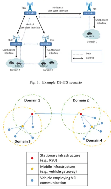
In D2-ITS, we leverage network programmability enabled by the separation between the network control- and data planes to achieve flexibility and agility. However, we go a step further by proposing a logically distributed network control plane which can dynamically adjust to current environment condi-tions and network characteristics to support ITS’ scalability, delay intolerance, and decentralization. D2-ITS’ distributed control plane employs a hierarchy of “controllers” as exem-plified in Figure 1. In this example ITS scenario, vehicles connect to road-side units (RSUs) which in turn are connected through a back haul network (e.g., Radio Base Stations, or RBSs). Controllers are placed at RSUs and control vehicles within their “domain”. As illustrated in Figure 2, an RSU’s domain is defined by its communication range. We consider that RSUs employ low range communication technologies such as IEEE 802.11 and its variants. At the next level up the control hierarchy, controllers are placed at RBSs and control their own domain, which could span RSUs within the RBS’ communication range. Control is thus decentralized since controllers do not necessarily have complete state information about the network and participants.
Control Plane
As illustrated in Figure 1, control plane communication happens through the “east-west” interface between controllers at the same hierarchical level (“horizontal” east-west commu-nication) or between controllers at different levels (“vertical” east-west communication). Controllers use the equivalent to SDN’s southbound interface API to communicate with nodes (i.e., vehicles) they control, which are equipped with software switches, e.g., SDN-enabled (not shown in the figure). RSUs are also equipped with software switches such that they can relay data messages.
Data Plane
Data is forwarded according to routing/forwarding policies established by the domain’s controller, the local RSU in our example scenario. We should point out that since RSUs and RBSs are also part of the data forwarding infrastructure, they can also participate in data forwarding. For instance, if node 1 in Domain A (see Figure 1) needs to communicate with node 2 in Domain B, it will do so through Domain A’s RSU which will relay traffic to Domain B’s RSU. Alternatively, as indicated in Figure 1, data can flow directly between two domains as long as the controllers establish a direct data path. Figure 2 illustrates how control domains can be defined for infrastructure-based ITS scenarios, i.e., ITS deployments using infrastructure-based wireless communication (e.g., through
Fig. 1. Example D2-ITS scenario
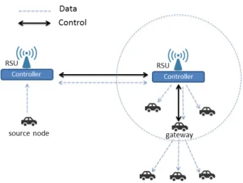
Fig. 2. Controller Domains
IEEE 802.11-enabled RSUs, LTE eNodeBs, etc). According to Figure 2, controllers located at RSUs or RBSs will control nodes within their communication range. If a node is located within range of more than one RSU, the node can decide which RSU will function as its controller using criteria such as the RSUs’ RSSI, etc. As previously pointed out, the RSU-resident controller can configure vehicles in its domain to send data packets directly to it using a vehicle-to-infrastructure (V2I) model, so that communication goes through a low-latency backbone. Vehicle-to-vehicle (V2V) communication could also be employed for data forwarding. Additionally, as shown in Figure 2, mobile infrastructure (e.g., mobile gateways in vehicles) capable of V2V communication can be used to extend coverage of stationary infrastructure.
III. ROADHAZARDWARNING(RHW) APPLICATION
D2-ITS’ current design is motivated by ITS message dis-semination applications, such as Road Hazard Warning (RHW)
services [1], [2] which use V2I communication to disseminate messages amongst vehicles.
Road Hazard Warning (RHW) [1], [2] is an event-based road message dissemination service specified by the European Telecommunications Standards Institute (ETSI). It defines a variety of events including traffic jams, hazardous conditions and messages that will be generated to alert road users (e.g., cars, trucks) of such events2.
For example, Decentralized Environmental Notification Messages (DENMs) [1] are mainly used to provide the neces-sary alerts in the case of emergency situations (e.g., eminent risk of collision) or warnings, e.g., in the event of a road congestion. As such, DENMs should be conveyed through the ITS infrastructure and delivered to road users in the geographic area affected by the event, or ”relevance area” [1].
Cooperative Awareness Messages (CAMs) [2], on the other hand, carry signaling information. CAM’s contents vary ac-cording to the type of RHW service. They may carry informa-tion about vehicle locainforma-tion, vehicle type, as well as time of day, vehicle speed, etc. Section IV-C describes how we implement RHW message dissemination atop our D2-ITS framework. A. Infrastructure-Based Communication
We consider scenarios in which RSUs are deployed along roads and highways to provide network coverage using short-or medium-range technologies. In our D2-ITS framewshort-ork, the RSU is a natural host for the controller, which manages its “domain” using specialized control applications running atop the controller. For instance, control applications can be tailored to cope with specific features of the area being serviced. For example, some regions can be sparser while others can be more dense.
Infrastructure-based communication in support of RHW services can employ only stationary infrastructure, i.e. RSUs. Alternatively, since in some cases deploying RSUs can be either technically or financially not viable, mobile, device-to-device communication capable gateways can be used to extend the scope of RSUs. They can connect vehicles that would be disconnected otherwise. Figure 3 illustrates the case in which a source node transmits messages that are forwarded both by the fixed infrastructure as well as mobile gateways in order to reach all their destinations. Mobile gateways can also be used to interconnect RSUs in regions where they are sparsely deployed.
B. RHW Message Dissemination
Below, we highlight some of the main RHW’s message dissemination assumptions, features, and requirements.
• Vehicle-to-infrastructure communication: V2I commu-nication is the default method of message dissemination; alternatively, the controller can establish direct vehicle-to-vehicle (V2V) paths. As previously discussed, the controller can also designate a vehicle as a gateway node,
2More information on ETSI Intelligent Transport Systems standards is
available at http://www.etsi.org/technologies-clusters/technologies/intelligent-transport.
Fig. 3. RHW communication using gateways
which would then relay messages to nodes for which it serves as gateway. Note that in the latter two cases, ve-hicles would need to be capable of V2V communication.
• Vehicle-to-vehicle communication: V2V
communica-tion can also be used to disseminate messages; it will be based on match-action tables installed by the appropriate controller.
• Vehicle position: a vehicle knows its position (e.g., using GPS) and transmits it periodically using CAMs to a controller in its communication range.
• Relevance area based message delivery: application messages should be routed to the appropriate relevance area; note that vehicles may be moving in and out of relevance areas.
• Relevance area: the relevance area of a given message
is computed by the corresponding controller.
• RSU coverage: RSUs have limited coverage so vehicles
could be outside the range of an RSU. As previously pointed out, RSUs can extend their coverage by designat-ing a vehicle in its range to act as a gateway to forward messages to other vehicles outside the RSU’s range. Note that there may be cases in which vehicles are not covered by an RSU.
• Message delivery priority: RHW messages require dif-ferent delivery priorities. For instance, messages that convey emergency situations will have higher priority over messages carrying information about general road conditions.
IV. D2-ITS DESIGN ANDIMPLEMENTATION
Using Road Hazard Warning services (RHW) as our use case allows us to show D2-ITS’ ability to handle RHW’s message delivery requirements. As the basis for our imple-mentation, we use the Libfluid [9] open-source controller and the Open vSwitch (OVS) software switch [10]. As we describe in detail in this section, some of our contributions include the design and implementation of the east-west interface for
controller-to-controller communication, as well as the exten-sion of the southbound controller-to-vehicle to include the new message types required by RHW services.
A. Message Types and Dissemination
The types of messages supported in our current D2-ITS implementation follow ETSI’s ITS specifications [1], [2] for RHW services as described in Section III.
• Decentralized Environmental Notification Messages
(DENMs) are forwarded by D2-ITS’ data plane and can be of the following types:
– Emergency are time-sensitive data plane messages sent by vehicles to their connected controller to convey information about nearby accidents, eminent risks, etc. They have the highest delivery priority. Controllers flood emergency messages to vehicles in their domain. We opted to follow the ETSI “aware-ness range” criteria, i.e., emergency messages are delivered to vehicles in the neighborhood using a time-to-live approach. We should point out that the D2-ITS framework can be adjusted to account for different message delivery criteria;
– Warning are also data plane messages. They are sent by vehicles to their connected controller to report abnormal situations on the road such as road congestion or traffic jams. Warnings are disseminated by controllers to vehicles within their relevance area. Depending upon the type of warning and the exten-sion of the area it affects, the controller can also forward such message to peer controllers, which in turn will decide how to forward the message further.
• Cooperative Awareness Messages (CAMs) are control plane messages which are sent periodically from a vehicle to a controller. They typically carry information about vehicles such as their current location, speed, etc. Controllers use location updates to compute relevance areas, compute and install routes in vehicles. This is similar to the concept of Local Dynamic Map (LDM) defined by ETSI [11]. These messages are also exchanged between controllers to exchange information about their respective domains.
• User Addition Requests: are another type of control
plane messages. They are sent by a vehicle to the controller to which the vehicle trying to connect. This message also serves to authenticate the vehicle with the controller. If security is not enforced, user addition requests are used for node identification purposes only.
• Controller HELLO are control plane messages used to advertise controller presence and build peering relations between pairs of controllers.
CAM and DENM messages are implemented using Open-Flow 1.3’s experimenter message. Experimenter messages are
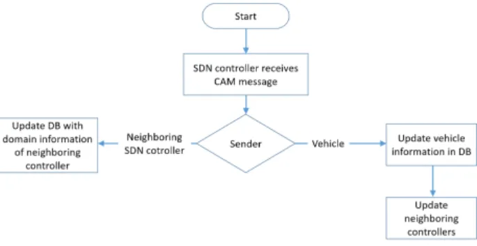
Fig. 4. D2-ITS controller’s processing of CAM messages
used in OpenFlow 1.3 as a way to enable extensions to the protocol without the need of a protocol version update. In our implementation, we use the payload of an experimenter message to carry the RHW messages described above (e.g., CAMs and DENMs). As shown in Figure 6, which illustrates the format of the experimenter message, we use the header to specify the message type and the length of its payload. The message type differentiates between different types of CAM and DENM messages.
B. D2-ITS Controller
As we elaborate in Section IV-A, each vehicle connected to a controller can send CAM and DENM messages. CAM mes-sages are also exchanged between neighboring controllers to notify each other about their respective domain. The flowcharts shown in Figure 4 and Figure 5 summarize how the D2-ITS controller handles the different types of messages it receives. Upon reception of a CAM message from a vehicle, the controller updates the corresponding information about the ve-hicle in its local database. Similarly, the controller updates its local database with the domain information of the neighboring controller upon the reception of CAM messages.
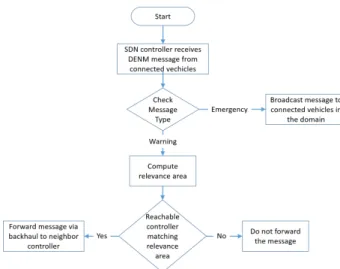
When DENM warning message is received by the controller it gets routed to the relevance area through backhaul network using east-west interface. Message routing is decided using the domain information of the neighboring controllers in the local database updated via CAM messages. Thus, geographic routing of the warning messages depends on the area relevant to the corresponding event.
DENM emergency message needs immediate action and hence is broadcasted by the controller upon its reception. The broadcasting of emergency messages is localized to the domain of the controller.
C. D2-ITS Prototype
We used the ns-3 simulator3 in conjunction with its Direct
Code Execution (DCE)4 module to prototype our framework. Using DCE allows execution of live code atop the ns-3 stack that enabled us to use open-source controllers, standardized APIs and software switches that are widely used.
3https://www.nsnam.org/
Fig. 5. D2-ITS controller’s processing of DENM messages
Fig. 6. Message format
As previously pointed out, D2-ITS enabled vehicles are based on the Open vSwitch (OVS) [10] software switch with OpenFlow suppport [12]. Libfluid [9] was used to provide a lightweight controller implementation. One main new fea-ture we added to the Libfluid controller is the east-west interface, which enables controller-to-controller communica-tion and OpenFlow experimenter messages. Addicommunica-tionally, as described in Section IV-A, we implemented D2-ITS control-(e.g., CAMs) and data plane messages (i.e., DENMs) using OpenFlow experimenter messages. To this end, we added new experimenter message types as well as the logic to generate and parse them.
Figure 7 illustrates D2-ITS’ prototype modules and their interactions. As shown in the figure, our customized versions of OVS and libfluid run atop the ns-3 userspace through DCE, enabling the OpenFlow protocol for any node interface. Node interfaces such as LTE and 802.11 variants can work atop a Linux kernel stack or atop a simulated ns-3 stack. Note that the RSU is implemented based on the modified libfluid controller while a vehicle is based on the modified OVS switch. Additionally, D2-ITS supports the use of mobile controllers, a feature that we discuss in Section V-C.
V. D2-ITSEVALUATION
As proof of concept, we showcase how our D2-ITS frame-work supports ITS applications. Our experiments aim at demonstrating the benefits of using a decentralized control plane approach for Road Hazard Warning services.
A. Experimental Methodology
We ran our experiments using the D2-ITS prototype built on ns-3/DCE. We conducted a side-by-side comparison between
Fig. 7. D2-ITS prototype
“distributed”- (D-ITS) and centralized (C-ITS) scenarios that are illustrated in Figures 8 and 9, respectively. D-ITS and C-ITS are setup as follows:
• D-ITS: two stationary RSUs (node 2 and node 3), each
co-located with a controller, are interconnected through a wireless network. Vehicles in an RSU’s range connect to the controller hosted by the RSU over IEEE 802.11 ad hoc mode; RSUs communicate through a point-to-point backhaul network;
• C-ITS: devices are associated to a single network-wide controller using the cellular network. In particular, as shown in Figure 9, we use an LTE network where the LTE base station, eNodeB, (node 0) is connected to the centralized controller through a backhaul network. Message generation: In our experiments, vehicles send peri-odic RHW messages that are either warning or emergency messages and are conveyed over V2I communication. As described earlier, warning messages should be routed to a relevance area (which may include multiple domains), while emergency messages should be broadcast locally in the do-main. Warning messages are generated every 3 seconds and emergency messages every 7 seconds.
Vehicle mobility: A grid of size 1000x800 meters was created to represent the road. In order to provide a realistic road network scenario, we simulate platoon of vehicles traveling on the road with a certain speed while the source node, which is also moving, sends warning and emergency messages. A few stationary cars are also placed along the roadside. We use SUMO (Simulation of Urban MObility) [13] to generate realistic vehicle mobility traces which were used as input to our ns-3/DCE simulations.
Table I presents the main parameters used for the D-ITS and C-ITS scenarios. In the case of C-ITS, the backhaul network uses ns-3’s point-to-point abstraction to connect the eNodeB LTE base station and the controller. We set the backhaul network delay to 100 milliseconds which is the upper bound delay expected for LTE mobile backhaul [14]. For a fair comparison, we use the same parameters for the D-ITS backhaul network, which connects the RSUs. Note that the
Fig. 8. D-ITS scenario
Fig. 9. C-ITS scenario
number of nodes for the D-ITS scenario is 14 while it is 12 for C-ITS. This is because the D-ITS scenario has two RSUs that are not present in C-ITS.
It is worth pointing out that in D-ITS, forwarding decisions are distributed across different controllers, while in C-ITS, a single controller is in charge of forwarding decisions. Another difference is that the C-ITS scenario imposes the maintenance of a network-wide database. In D-ITS, on the other hand, controllers do not need to keep a global view of the network state.
Evaluation metrics: Motivated by ITS’ low delay require-ments, we measure end-to-end latency as the time it takes for data messages (both warning and emergency) to be delivered from the source node to nodes in the message’s relevance area. We report latency results for both emergency and information messages. We also compute overhead as the ratio between the number of data bytes over the total number of control bytes generated.
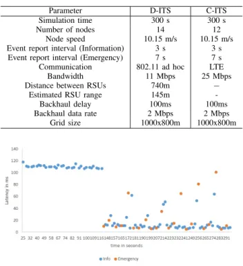
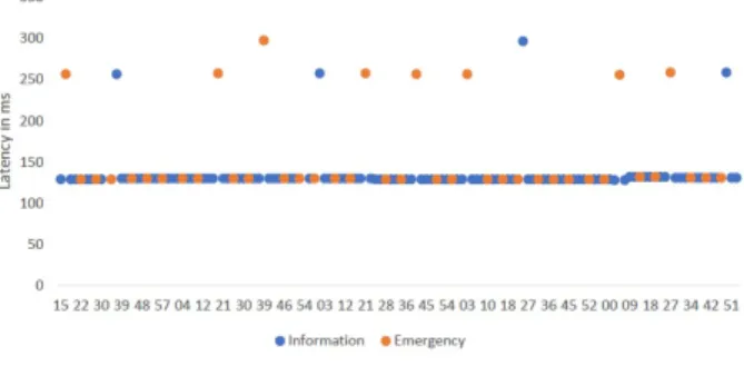
TABLE I SIMULATION PARAMETERS.
Parameter D-ITS C-ITS Simulation time 300 s 300 s Number of nodes 14 12
Node speed 10.15 m/s 10.15 m/s Event report interval (Information) 3 s 3 s Event report interval (Emergency) 7 s 7 s Communication 802.11 ad hoc LTE
Bandwidth 11 Mbps 25 Mbps Distance between RSUs 740m −
Estimated RSU range 145m -Backhaul delay 100ms 100ms Backhaul data rate 2 Mbps 2 Mbps
Grid size 1000x800m 1000x800m
Fig. 10. Distributed scenario (D-ITS). Latency graph for a stationary vehicle (vehicle 5) in the relevance area.
B. Results
We present results for mobile and stationary destination nodes in the relevance area. Each data point in the latency graphs below are averaged over 10 runs. Latency variations between different runs were negligible, therefore we do not show them. In the D-ITS scenario, nodes 7 to 13 are moving towards the relevance area, while nodes 5 and 6 are stationary located in the relevance area. In C-ITS, nodes 5 to 11 are mobile, while nodes 3 and 4 are stationary.
Figures 10 and 11 show how message delivery latency varies with time in the D-ITS scenario for a stationary- and mobile destination, respectively. Figure 12 shows latency results for a mobile node in the C-ITS scenario. We should point out that in the C-ITS scenario, there is no difference in delivery latency for stationary- or mobile nodes (so we only show a single latency graph for the C-ITS scenario). This is because nodes are always connected to the centralized controller. We should also note that the graphs shown for an individual node are representative (i.e., show similar results and trends) of that node’s category (e.g., all mobile- or all stationary nodes in the experiment). Note that the stationary vehicles, namely nodes 5 and 6 in the D-ITS scenario, remain connected to RSU node 3 throughout the lifetime of the experiment, while mobile vehicles (nodes 7-13) connect to RSU node 3 only during the time they are in RSU node 3’s range. In the C-ITS scenario, vehicles are always connected to the centralized controller (node 0). Consequently, as shown in Figure 12, we observe that: (1) delivery latency is constant throughout the
Fig. 11. Distributed scenario (D-ITS). Latency graph for a mobile vehicle (vehicle 7) approaching the relevance area.
Fig. 12. Centralized scenario (C-ITS). Latency graph for a mobile vehicle (vehicle 3) in the relevance area.
experiment (except for some outliers that will be discussed below); (2) there is no difference in latency for emergency or warning messages.
In contrast, in the D-ITS scenario, emergency messages are delivered only to the vehicles located in the area affected by the event that triggered the message and are consistently delivered with much lower latency when compared to the C-ITS scenario. In our experiments, the average latency for emergency messages is 18ms (accounting for the outliers shown in the graphs) while in the C-ITS case, it is 142ms, which is the same for warning messages, as previously pointed out. Note that in Figure 11 messages were not delivered when the vehicle was outside the relevance area.
In the case of warning messages, overall, they experience lower latency in the D-ITS scenario (average latency of 110ms) when compared to C-ITS (average latency of 142ms). Warning message latency depends on the location of the sender relative to the receiver. For instance, in Figure 10, up to about 116 seconds, the source node is connected to RSU node 2, forcing warning messages to travel across different domains through decentralized controllers so they can reach the relevance area covered by RSU node 3. This results in latency varying from 115 to 120 milliseconds.
We calculated the overhead for both scenarios and our results show that the overhead incurred by the D-ITS scenario is only 6.5% higher than C-ITS’s overhead.
Figure 10 also shows that the source node cannot connect to a controller between 110 to 145 milliseconds. The reason
is that 802.11 communication range is not enough to provide connectivity in the region between RSU nodes 2 and 3 (recall that RSUs are 740m away from each other). During this period, the source node does not send any messages until it connects to RSU node 3 at second 145. Such connection allows messages to be disseminated within a single domain with latency results varying from 7 to 10 milliseconds.
Figure 11 depicts latency results for warning messages received by a mobile vehicle (node 7). As previously noted, even though we show results for node 7, they are similar to every other mobile node in the experiment (i.e., nodes 7-13). According to the figure, node 7 only receives warning messages while in the relevance area and connected to RSU node 3. This explains the zero latency points in the figure, which represent messages not being received by the node.
Figure 10 also shows that emergency messages are localized to a single domain, resulting in delivery with low latency. A stationary vehicle does not receive emergency messages until time 145 seconds, i.e., when source node finds itself in the same domain as its (stationary) destination.
We observe that, in some cases, emergency and warning messages experienced considerably higher latency when compared to the average latency. Vehicle mobility increases the chance of such anomaly in the simulated experiment. Also, latency can increase as vehicles reach the edge of the RSU coverage area.
In summary, our experiments highlight that the proposed framework can yield lower message delivery latency for Intel-ligent Transport Systems services such as RHW. In particular, we show that emergency messages can be delivered with significantly lower latencies (in our experiments, one order of magnitude lower) when compared to a centralized control plane approach with only a slight increase in overhead. C. Discussion
As described previously, D2-ITS’ current implementation focused on ITS’ RHW services. However, D2-ITS can be extended to include other features and functionality so that it can be used by other ITS applications. Below we describe some of these extensions.
Vehicle-to-vehicle communication: as mentioned in Section III-A, our framework can be extended to support V2V communication. We provided the example of a mobile gateway that extends the domain of a RSU by forwarding data packets to neighbors (Figure 3). One of the challenges is to provide the controller with sufficient information to control a gateway. For instance, the controller should be aware of nodes in the gateways’ vicinity, including their position. Such information would enable the controller to define message relevance areas, i.e., decide which nodes should receive which data messages.
Vehicle-controller discovery: our framework allows vehicles to establish a connection with a controller for exchanging control and data packets. Even though we did not explore how such connection can be established dynamically, it is an important challenge to be addressed. OpenFlow allows multiple controller connection for a single switch with the restriction of defining a single controller in charge (or a master controller). However, there is no protocol for dynamic switch-controller association. In our experiments, it is possible to predict when a vehicle will be in the range of an RSU, and thus, of a controller. This helps in defining when a vehicle should become part of a controller’s domain.
Mobile controller: disconnections between vehicles and con-trollers may happen very often in ITS due to mobility, RSU coverage, etc. One way to mitigate control plane disconnec-tions is to use mobile controllers. For example, in Figure 3, a gateway could act as a controller through a delegation process [15], i.e., a higher layer controller could offload tasks to the new instantiated controller. The work in [16] provides an example of task offloading using local controllers, but does not address challenges such as dynamically defining what tasks should be delegated and when they should be offloaded.
VI. RELATEDWORK
VANETs: some of the main challenges of VANETs relate to efficient and reliable message dissemination. Many protocols usually mitigate the broadcast storm problem using techniques for broadcast suppression (e.g., [17]), limiting the number of relay nodes. A common method to nominate relay nodes in VANETs is based on node position and moving direction (e.g., [18], [19]). The appropriate selection of relay nodes also impacts in reliability. For instance, mobility prediction can be employed for improved message delivery rate [20].Reliabilty is also a challenge for VANETS in ITS due to the link stability. The work in [21] proposes the grouping of vehicles according to their velocity. The results have shown increase in link duration, reduction in the number of link-breakage events and increase in the end-to-end throughput.
Software Defined VANETs: Ku et al. [7] propose an architec-ture for software-defined VANETs. The architecarchitec-ture assumes a logically centralized intelligence for the entire VANET system. Based on simulation results which evaluate routing performance, the authors show that SDNs are beneficial for VANETs when compared to wireless, multihop ad-hoc net-work (MANET) solutions. They demonstrate that transmission power adjustment is another feature that can be provided using SDN.
Petit et al. [22] investigate the feasibility of vehicles acting as data relays between RSUs. They consider the scenario in which RSUs have no wired or wireless connectivity between them and use vehicle mobility to relay data amongst RSUs. They find that the throughput obtained is directly proportional to the peak rate of the wireless channel used for vehicle-to-roadside communication.
DeVANET [23] proposes a decentralized software-defined VANET architecture in which each ”domain” has its own centralized SDN controller. A ”root” controller receives do-main information such as link state and host presence from domain controllers. From its description in [23], DeVANET does not consider dynamic control distribution in response to application needs and current network and environment conditions. Additionally, its implementation and consequently experimental evaluation are quite limited.
Other efforts such as [24] and [25] consider SDN-enabled RSUs for VANETs. This approach allows dynamic path computation by an SDN controller. An interesting concept is the RSU cloud [26] in which a customized RSU can host services for vehicles. It employs SDN to dynamically instantiate, replicate, and/or migrate services.
Software Defined Networking: the concept of local controllers was firstly advocated by Kandoo [16] in order to reduce the load on the global controller. Local controllers filter the number of new flow requests. The work in [27] investigates the relation between algorithms to manage distributed controllers and algorithms to maintain local controllers. Usman et al. [28] propose a hierarchical D2D communication architecture for public safety applications that also uses the concept of local controllers. Formation and management of mobile clouds of devices are the main goal of the architecture.
The framework proposed here provides a flexible control plane that can automatically adjust as a function of the dynamics of the underlying environment in order to address application requirements. Control can be distributed as needed: for example, controllers can be instantiated at different ITS control levels, e.g., at RSUs or in vehicles within groups of vehicles. That way, decisions can be made locally using only locally-relevant information, for example in order to satisfy stringent latency requirements. Local control also allows the system to scale as well as improve its robustness to connectiv-ity disruptions. The use case scenario presented in the previous section shows a proof-of-concept of our D2-ITS prototype and demonstrates that it can achieve lower message delivery latency with minimal additional overhead.
VII. CONCLUSION ANDFUTUREWORK
In this paper, we propose the D2-ITS framework which uses network programmability to support message dissemi-nation services for Intelligent Transport Systems. We describe D2-ITS decentralized control plane architecture, design, and prototype implementation. Our proof-of-concept experiments using the ns-3/DCE simulation platform show that D2-ITS yields lower message delivery latency with minimal additional overhead.
We plan to pursue the following directions of future work: control plane load balancing and fault tolerance, security, and administrative decentralization and autonomy. We also plan to carry on further experiments using Mininet-Wifi [29].
VIII. ACKNOWLEDGMENTS
This work has been partially supported by NSF under grant CNS 1321151 and by the French Government (National Re-search Agency, ANR) through the Investments for the Future Program under grant ANR-11-LABX-0031-01. Mateus A. S. Santos is currently with Ericsson Research.
REFERENCES
[1] ETSI, “Intelligent transport systems; vehicular communications; basic set of applications; specifications of decentralized environmental notifi-cation basic service,” ETSI, Tech. Rep. EN 302 637-3 V1.2.1, 2014. [2] ——, “Intelligent transport systems; vehicular communications; basic
set of applications; specification of cooperative awareness basic service,” ETSI, Tech. Rep. EN 302 637-2 V1.3.1, 2014.
[3] D. Jiang and L. Delgrossi, “IEEE 802.11p: Towards an international standard for wireless access in vehicular environments,” in Vehicular Technology Conference, 2008. VTC Spring 2008. IEEE. IEEE, 2008, pp. 2036–2040.
[4] M. Amadeo, C. Campolo, and A. Molinaro, “Enhancing IEEE 802.11 p/WAVE to provide infotainment applications in VANETs,” Ad Hoc Networks, vol. 10, no. 2, pp. 253–269, 2012.
[5] G. Araniti, C. Campolo, M. Condoluci, A. Iera, and A. Molinaro, “LTE for vehicular networking: a survey,” Communications Magazine, IEEE, vol. 51, no. 5, pp. 148–157, 2013.
[6] N. B. Truong, G. M. Lee, and Y. Ghamri-Doudane, “Software defined networking-based vehicular adhoc network with fog computing,” in Integrated Network Management (IM), 2015 IFIP/IEEE International Symposium on. IEEE, 2015, pp. 1202–1207.
[7] I. Ku, Y. Lu, M. Gerla, F. Ongaro, R. L. Gomes, and E. Cerqueira, “To-wards software-defined VANET: Architecture and services,” in Ad Hoc Networking Workshop (MED-HOC-NET), 2014 13th Annual Mediter-ranean. IEEE, 2014, pp. 103–110.
[8] M. Karakus and A. Durresi, “A survey: Control plane scalability is-sues and approaches in software-defined networking (SDN),” Computer Networks, 2016.
[9] A. Vidal, C. E. Rothenberg, and F. L. Verdi, “The libfluid openflow driver implementation,” in Proceedings of SBRC, 2014.
[10] B. Pfaff, J. Pettit, T. Koponen, E. J. Jackson, A. Zhou, J. Rajahalme, J. Gross, A. Wang, J. Stringer, P. Shelar, K. Amidon, and M. Casado, “The design and implementation of open vSwitch,” in Proceedings of the 12th USENIX Conference on Networked Systems Design and Imple-mentation, ser. NSDI’15. Berkeley, CA, USA: USENIX Association, 2015, pp. 117–130.
[11] ETSI, “Intelligent Transport Systems (ITS); Vehicular Communications; Basic Set of Applications; Local Dynamic Map (LDM),” ETSI, Tech. Rep. EN 302 895, 2014.
[12] N. McKeown, T. Anderson, H. Balakrishnan, G. Parulkar, L. Peterson, J. Rexford, S. Shenker, and J. Turner, “Openflow: enabling innovation in campus networks,” ACM SIGCOMM Computer Communication Review, vol. 38, no. 2, pp. 69–74, 2008.
[13] D. Krajzewicz, J. Erdmann, M. Behrisch, and L. Bieker, “Recent devel-opment and applications of SUMO - Simulation of Urban MObility,” International Journal On Advances in Systems and Measurements, vol. 5, no. 3&4, pp. 128–138, December 2012.
[14] E. Piri and J. Pinola, “Performance of lte uplink for iot backhaul,” in 2016 13th IEEE Annual Consumer Communications Networking Conference (CCNC), Jan 2016, pp. 6–11.
[15] M. A. Santos, B. A. Nunes, K. Obraczka, T. Turletti, B. T. de Oliveira, and C. B. Margi, “Decentralizing SDN’s control plane,” in Local Computer Networks (LCN), 2014 IEEE 39th Conference on. IEEE, 2014, pp. 402–405.
[16] S. Hassas Yeganeh and Y. Ganjali, “Kandoo: a framework for efficient and scalable offloading of control applications,” in Proceedings of the first workshop on Hot topics in software defined networks. ACM, 2012, pp. 19–24.
[17] N. Wisitpongphan, O. K. Tonguz, J. S. Parikh, P. Mudalige, F. Bai, and V. Sadekar, “Broadcast storm mitigation techniques in vehicular ad hoc networks,” IEEE Wireless Communications, vol. 14, no. 6, pp. 84–94, December 2007.
[18] M.-T. Sun, W.-C. Feng, T.-H. Lai, K. Yamada, H. Okada, and K. Fu-jimura, “GPS-based message broadcasting for inter-vehicle communi-cation,” in Parallel Processing, 2000. Proceedings. 2000 International Conference on. IEEE, 2000, pp. 279–286.
[19] M. Mariyasagayam, T. Osafune, and M. Lenardi, “Enhanced multi-hop vehicular broadcast (MHVB) for active safety applications,” in Telecommunications, 2007. ITST’07. 7th International Conference on ITS. IEEE, 2007, pp. 1–6.
[20] P. Lai, X. Wang, N. Lu, and F. Liu, “A reliable broadcast routing scheme based on mobility prediction for VANET,” in Intelligent Vehicles Symposium, 2009 IEEE, June 2009, pp. 1083–1087.
[21] T. Taleb, E. Sakhaee, A. Jamalipour, K. Hashimoto, N. Kato, and Y. Nemoto, “A Stable Routing Protocol to Support ITS Services in VANET Networks,” vol. 56. IEEE, 2007, pp. 3337–3347.
[22] B. Petit, M. Ammar, and R. Fujimoto, “Protocols for roadside-to-roadside data relaying over vehicular networks,” in Wireless Communi-cations and Networking Conference, 2006. WCNC 2006. IEEE, vol. 1. IEEE, 2006, pp. 294–299.
[23] A. Kazmi, M. A. Khan, and M. U. Akram, “DeVANET: decentralized software-defined VANET architecture,” in Cloud Engineering Workshop (IC2EW), 2016 IEEE International Conference on. IEEE, 2016, pp. 42–47.
[24] G. Luo, S. Jia, Z. Liu, K. Zhu, and L. Zhang, “sdnMAC: a software defined networking based mac protocol in VANETs,” in Quality of Service (IWQoS), 2016 IEEE/ACM 24th International Symposium on. IEEE, 2016, pp. 1–2.
[25] Y.-C. Liu, C. Chen, and S. Chakraborty, “A software defined network architecture for geobroadcast in VANETs,” in Communications (ICC), 2015 IEEE International Conference on. IEEE, 2015, pp. 6559–6564. [26] M. A. Salahuddin, A. Al-Fuqaha, and M. Guizani, “Software-defined networking for rsu clouds in support of the internet of vehicles,” IEEE Internet of Things journal, vol. 2, no. 2, pp. 133–144, 2015.
[27] J. S. Stefan Schmid, “Exploiting locality in distributed SDN control,” in HotSDN ’13 Proceedings of the second ACM SIGCOMM workshop on Hot topics in software defined networking. ACM, 2013, pp. 121–126. [28] M. Usman, A. A. Gebremariam, U. Raza, and F. Granelli, “A software-defined device-to-device communication architecture for public safety applications in 5G networks,” Access, IEEE, vol. 3, pp. 1649–1654, 2015.
[29] R. R. Fontes, S. Afzal, S. H. B. Brito, M. A. S. Santos, and C. E. Rothenberg, “MiniWiFi: Emulating software-defined wireless net-works,” in 2015 11th International Conference on Network and Service Management (CNSM), Nov 2015, pp. 384–389.