Publisher’s version / Version de l'éditeur:
Journal of Fluids and Structures, 13, August 6, pp. 723-754, 1999
READ THESE TERMS AND CONDITIONS CAREFULLY BEFORE USING THIS WEBSITE. https://nrc-publications.canada.ca/eng/copyright
Vous avez des questions? Nous pouvons vous aider. Pour communiquer directement avec un auteur, consultez la
première page de la revue dans laquelle son article a été publié afin de trouver ses coordonnées. Si vous n’arrivez pas à les repérer, communiquez avec nous à PublicationsArchive-ArchivesPublications@nrc-cnrc.gc.ca.
Questions? Contact the NRC Publications Archive team at
PublicationsArchive-ArchivesPublications@nrc-cnrc.gc.ca. If you wish to email the authors directly, please see the first page of the publication for their contact information.
NRC Publications Archive
Archives des publications du CNRC
This publication could be one of several versions: author’s original, accepted manuscript or the publisher’s version. / La version de cette publication peut être l’une des suivantes : la version prépublication de l’auteur, la version acceptée du manuscrit ou la version de l’éditeur.
For the publisher’s version, please access the DOI link below./ Pour consulter la version de l’éditeur, utilisez le lien DOI ci-dessous.
https://doi.org/10.1006/jfls.1999.0231
Access and use of this website and the material on it are subject to the Terms and Conditions set forth at
A numerical study of unsteady fluid flow in in-line and staggered tube
banks
Beale, Steven; Spalding, D. B.
https://publications-cnrc.canada.ca/fra/droits
L’accès à ce site Web et l’utilisation de son contenu sont assujettis aux conditions présentées dans le site LISEZ CES CONDITIONS ATTENTIVEMENT AVANT D’UTILISER CE SITE WEB.
NRC Publications Record / Notice d'Archives des publications de CNRC:
https://nrc-publications.canada.ca/eng/view/object/?id=f9fb4981-fbb6-4717-a9a0-34181373f5b2 https://publications-cnrc.canada.ca/fra/voir/objet/?id=f9fb4981-fbb6-4717-a9a0-34181373f5b2
Journal of Fluids and Structures(1999) 13, 723}754
A NUMERICAL STUDY OF UNSTEADY FLUID FLOW IN
IN-LINE AND STAGGERED TUBE BANKS
S. B. BEALE
National Research Council of Canada, Montreal Road Ottawa, Ontario K1A 0R6, Canada
AND
D. B. SPALDING
Concentration Heat and Momentum ¸td., Bakery House, 40 High Street
Wimbledon, London SW19 5AU, U.K.
(Received 7 July 1998 and in revised form 19 March 1999)
This paper is concerned with the results of numerical calculations for transient#ow in in-line-square and rotated-in-line-square tube banks with a pitch-to-diameter ratio of 2 : 1, in the Reynolds number range of 30}3000. Transient-periodic behaviour is induced by the consideration of two or more modules, with a sinusoidal span-wise perturbation being applied in the upstream module. There is a triode-like e!ect, whereby the downstream response to the stimulus is ampli"ed, and there is a net gain in the crosswise #ow component. When an appropriate feedback mechanism is provided, a stable transient behaviour is obtained, with alternate vortices being shed from each cylinder. Flow visualization studies of the results of the calcu-lations are presented together with quantitative details of pressure drop, lift, drag and heat transfer. For the staggered bank, a wake-switching or Coanda e!ect was observed as the serpentine-shaped wake attached to alternate sides of the downstream cylinder. The induced response is independent of the amplitude and frequency of the applied disturbance, including the case of spontaneous behaviour with no excitation mechanism. For the in-line case where each cylinder is in the shadow of the previous one, the motion is less pronounced; however, a shear-layer instability associated with the alternating spin of shed vortices was observed. In this case, the response was found to be somewhat dependent on the frequency of the applied disturbance, and a transient motion could not be induced spontaneously in the absence of an explicit feedback mechanism. Calculated Strouhal numbers were in fair agreement with experi-mental data: for the staggered geometry, they had values of between 0)26 and 0)35, or from !21 to #6% higher than measured values, while for the in-line geometry, the Strouhal numbers ranged between 0)09 and 0)12, or about 20}40% lower than experimental values.
(1999 National Research Council of Canada
1. INTRODUCTION 1.1. GENERALBACKGROUND
Banks of plain tubes are often used in cross-#ow heat exchanger designs, because they combine ease of construction with reasonable thermal and mechanical e$ciency. Both in-line and staggered geometries are commonly employed. Although it was once maintained that there was insu$cient space for vortices to develop in the passages of tube banks (Owen 1965; LeFeuvre 1973), the results of#ow-visualization studies suggest that vortex shedding is present in tube banks, and that together with the phenomena of acoustic coupling and Article No.: j#s. 1999.0231 available online at http://www.idealibrary.com on
turbulent bu!eting, it can contribute to #ow-induced vibrations. The reader is referred to the review paper by PamK doussis (1982).
Early#ow-visualization studies (Wallis 1939) described alternate shedding of &&eddies'' in both in-line and staggered tube banks. More recently, Weaver & Abd-Rabbo (1985) published the results of visualization work on an in-line square bank with pitch-to-diameter ratio (s/d"1)5) while Abd-Rabbo & Weaver (1986) and Price et al. (1991) investigated a rotated-square bank (s/d"1)5) and Polak & Weaver (1995) published results for an equilateral triangular array (s/d"1)14!2)67). The 16 mm "lm clip by Weaver & Abd-Rabbo (1984) shows transient phenomena in both stationary and vibrating tube banks. Ziada et al. (1989) and Ziada & OengoK ren (1992) also conducted #ow-visualization studies of in-line banks with crosswise and streamwise pitch-to-diameter ratios (sy/d]sx/d) of 1)6]1)35 and 2)25]1)75, respectively.
Transient periodic phenomena are characterized by a Strouhal number, Sh, de"ned by Sh"fd
um, (1)
where d is the cylinder diameter, um is the bulk velocity in the minimum cross-section, or interstitial velocity, and f is a characteristic frequency. The Strouhal number is to be considered a function of the#ow Reynolds number
Re"oumd
k , (2)
where o is the #uid density, and k is #uid viscosity. Some authors base Re and Sh on a super"cial velocity ;m"um(sy!d)/sy in place of equations (1) and (2). Various re-searchers have published Sh data and correlations of data for tube banks (Chen 1968; Fitz-Hugh 1973; Polak & Weaver 1995; Rae & Wharmby 1987; Weaver et al. 1986; Z[ ukauskas et al. 1988; Z[ukauskas & Katinas 1988).
Computational #uid dynamics has been used to provide insight into the transport processes within the passages of heat exchangers and elsewhere. These studies enhance (and to some extent o!set) the need for expensive and intrusive experimental test rigs. Many numerical studies have been conducted on vortex shedding in single tubes (Braza et al. 1984; Borthwick 1986; Eaton 1987; Gresho et al. 1984; Jordan & Fromm 1972; Lecointe & Piquet 1984; Sa & Chang 1991); there have been fewer published on vortex shedding past pairs of cylinders (Chang & Song 1990; Ng et al. 1997), past two-row banks (Torikoshi et al. 1995), or past larger numbers of cylinders (Johnson et al. 1993).
To date, most numerical studies on doubly periodic tube banks are for steady, fully developed#ow at low Re laminar, or for steady, high Re turbulent #ow (Antonopoulos 1979; LeFeuvre 1973). The results of large-eddy simulations for very high Re turbulent#ow in tube banks (Pruitt et al. 1990; Stuhmillar et al. 1988) have also appeared, but there do not appear to be studies of unsteady, fully developed#ow in the laminar regime. This paper investigates the stability of laminar#uid #ow for in-line square and rotated-square tube banks with a pitch-to-diameter ratio of 2 : 1. The main goals of the work were to identify the fundamental excitation mechanisms which induce transient periodic behaviour in tube banks, and to perform and display the results of calculations in terms of qualitative and quantitative aspects of the resulting#ow "elds.
1.2. NUMERICALPROCEDURE
The solution procedure used in this study is a"nite-volume method which has existed for more than two decades. As most of the concepts described below are well known, the 724 S. B. BEALE AND D. B. SPALDING
description of the method has been kept brief. The procedure used is a version of the SIMPLE (Semi-Implicit Method for Pressure-Linked Equations) algorithm [Patankar & Spalding (1972); also see Caretto et al. (1972), Patankar (1980) and Spalding (1980)].
It is assumed that the transport of some general conserved property / is given by R(o/)
Rt #div(ou/)"div(Cgrad /)#S, (3)
where /"1 (continuity), /"i (enthalpy) and /"(u, v) (momentum).
The"nite domain is tessellated into discrete subdomains or cells by means of a structured grid (Beale 1993a). The nonlinear equation (3) is then approximated by linear algebraic equations with the form
aW(/W!/P)#aE(/E!/P)#aS(/S!/P)#aN(/N!/P)#aT(/T!/P)#SP"0, (4) where the subscripts =, E, S and N refer respectively to the west, east, south and north neighbours of P, and ¹ refers to the value of / at the previous time-step. The linking a-coe$cients are evaluated by means of a hybrid scheme (Spalding 1972) for the convec-tion-di!usion terms, and a fully implicit scheme for the transient term. The source term SP is linearized as
SP"C(<!/P), (5)
where C is a source-term coe$cient, and < a source-term value consistent with the other terms in the"nite-volume equations.
Velocity resolutes in the local curvilinear directions located at staggered-cell locations (Harlow & Welch 1965) are the independent variables in the momentum equations. These are solved with a guessed pressure "eld (pressure gradient is treated as a source in the momentum equations). At the end of any given&&sweep'', the velocity "eld will not satisfy the equation of continuity if the pressure"eld is incorrect; pressure and velocity correction factors are then computed, and the process is reiterated until the residual errors are reduced to negligibly small values. Some of the grid cells pass through regions of solid material, within which appropriate terms in the"nite-volume equations are cut out (Patankar 1980). The computer code utilized was the general-purpose, research-oriented code PHOENICS (Spalding 1982, 1984).
1.3. BOUNDARYCONDITIONS
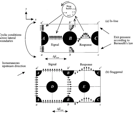
Ideally, #ow-"eld calculations would be performed over entire banks of tubes. Heat exchangers, however, contain very large numbers of tubes, and it is not feasible to construct a mesh large enough to cover the entire bank, and at the same time"ne enough to capture details of the #ow in the boundary layer and wake of every tube; so, it is necessary to di!erentiate between calculations on the overall mechanical and thermal performance of heat exchangers, and detailed simulations within the passages of the apparatus (Spalding 1981a, b; Beale 1997a, b). For the latter, it is required to develop a rationale based on one or more typical modules, on the assumption that unsteady, fully developed, periodic condi-tions prevail. The general approach taken is to consider at least two complete modules in the streamwise x-direction, apply a transient-periodic disturbance at the upstream module, measure the downstream response, then feed this back as the disturbance later, after at least one cycle of motion (and preferably several) have elapsed. Figure 1 shows the modules considered here.
In conventional#ow problems, the inlet and outlet are de"ned unambiguously. Many boundary prescriptions are possible, though typically a constant inlet mass #ux
SP"mR"oAu is speci"ed in the continuity equation together with upstream scalar sources SP"mR/"oAu/. The value of the pressure must also be "xed somewhere in the #ow "eld, and this may be achieved by a linear relationship between the downstream in-cell pressure pP and some external value p= (often taken to be zero), by setting a mass source SP"C(pP!p=) in the continuity equation. The conservative form of the SIMPLE algo-rithm ensures a balance between the inlet and exit mass sources or sinks, while the magnitude of C controls how close the pp and p= will be.
It is assumed that a transient-periodic behaviour has been established in the interior of the tube bank, either spontaneously or by some externally applied upstream stimulus. For steady, fully developed#ow (Beale & Spalding 1998), the velocity "eld is considered to be doubly periodic, with u(x, y)"u(x#sx, y)"u(x, y#sy) and the pressure p at any position may be considered to be composed of a linear term in the streamwise x-direction and a doubly periodic term. For fully developed transient#ow, there will be temporal #uctu-ations in the velocity"eld, so that
u(x, y, t)"u(x, y#sy, t#qy)"u(x#sx, y, t#qx) (6)
and,
p(x, y, t)"p(x, y#sy, t#qy)"p(x#sx, y, t#qx)#DpN308, (7) where the average row pressure drop DpN
308is just DpN 308" 1 t : t p(x, t)!p(x#sx, t)dt, (8) p(x, t)"
P
sy@2 y/~sy@2 p(x, y, t) dyP
sy@2 y/~sy@2 dy (9)evaluated within the #uid phase only, and qx and qy are phase di!erences between the #uctuating components at x and x#sx, and at y and y#sy, respectively. An immediate problem arises, namely thatqx and qy are not known a priori. In the absence of any further information, cyclic boundary conditions were imposed along the length of the lateral boundary (a-b-c and a@-b@-c@). Nontrivial values of qx were, however, allowed to evolve, as described further below.
Initial"elds for state variables were obtained from a partially converged solution to the steady-#ow problem in preference to the fully converged solution, since the latter had the tendency to elongate and dissipate the initial wake vortices at the outset of the calculations.
The methodology adopted was the following (see Figure 1).
(i) An upstream disturbance <0sin(2pf0t) was applied to the v-momentum equation between cylinders A and B [Figure 1(a)] for an initial period of three complete cycles. A uniform#ow in the x-direction, DuD"um, was prescribed at the inlet a-a@.
(ii) At each time-step, the downstream lateral v-responses between cylinders B and C, and the u-values along b-b@ were measured and stored in ring bu!ers.
(iii) After the initial period, the stored u-values were applied upstream as the in#ow along a-a@, and the v-responses as the upstream disturbances between A and B.
Steps (ii) and (iii) were then reiterated until either the disturbance died out, or a fully developed transient periodic behaviour was obtained. Treatment of the in-line and stag-gered geometries was essentially identical, apart from the presence of additional rows of 726 S. B. BEALE AND D. B. SPALDING
Figure 1. Boundary condition prescription for in-line and staggered tube banks.
tubes in the latter case, as indicated in Figure 1(b). Because the domain boundaries were chosen to correspond to inlet-exit zones, upwind boundary values were presumed to predominate, and streamwise di!usion was neglected (though, in fact, both in#ow and out#ow may occur for a brief moment at all boundaries for the staggered geometry). In certain cases, the lateral feedback mechanism was disabled in order to generate spontan-eously induced periodic #ow. The streamwise inlet boundary conditions, however, were always prescribed as described above. The downstream pressure pp was computed from the downstream velocity"eld by means of Bernoulli's law with pp"!12ou2p, where pP and uP are in-cell values of velocity and pressure near the exit. This is achieved with a coe$cient C"J2o/p
P and a value <"0 along the outlet cell row in the continuity (pressure correction) equation.
Heat transfer was also modelled as part of this study, and was assumed to occur under conditions of constant wall-heat#ux. The temperature "eld, far from the entrance to the tube bank, is considered to be such that
¹(x, y, t)"¹(x, y#sy, t#qy)"¹(x#sx, y, t#qx)#D¹Mb, (10) and D¹M
bis the di!erence in time-average bulk #uid temperature between two adjacent rows D¹M b" 1 t: t (¹b(x, t)!¹b(x#sx, t))dt, (11)
where ¹ b"
P
sy@2 y/~sy@2 ou(x, y, t)¹(x, y, t) dyP
sy@2 y/~sy@2 ou(x, y, t) dy (12)is evaluated in the#uid alone. The time-average upstream bulk temperature was set to be zero by subtracting the time-average value ocp¹1b across b-b@ from previously stored enthalpy values prior to back-substitution at a-a@.
1.4. PARAMETERSCONSIDERED
A number of tests were conducted to investigate the stability of the #ow to induced perturbations, capture features of the transient nature of #uid #ow, and the excitation mechanism in the passages of tube banks. Calculations were performed to investigate:
(i) the stimulated induction of a transient periodic behaviour and the passive generation of a transient oscillation in the absence of any speci"c excitation mechanism;
(ii) the threshold Re above which instabilities arise and the in#uence of the excitation frequency f0 of the initial applied disturbance on the long-term frequency of the response f; (iii) the in#uence of the amplitude <0 (this included the case <0"0) on the "nal amplitude <and frequency f of the simulation;
(iv) calculated values of Sh as compared to data obtained from experimental data and empirical correlations; and
(v) the e!ect of the vortex generation process on the pressure applied to the cylinder walls, as well as on quantitative performance measures such as lift, drag and heat-transfer coe$cients.
2. RESULTS
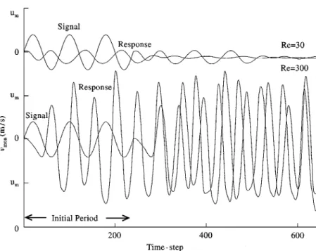
The results were obtained with a total of 640 time-steps (staggered) or 960 time-steps (in-line) which corresponds to eight cycles per run, on the assumption that Sh0"f0d/um of 0)2 (staggered) or 0)1 (in-line), at 40 sweeps per time-step, and 20 iterations per sweep. Animated sequences of velocity vectors, particle traces, streamlines, pressure and temper-ature contours were prepared by means of#ow visualization software (Watson et al. 1990). Figure 2 shows the stimulated response to an upstream spanwise disturbance for the staggered tube bank. The lateral v-velocities at monitor points located midway between cylinders A and B (upstream) and between B and C (downstream) are presented. It can be seen that, whereas at Re"30 the response dies down with time, at Re"300 the signal is ampli"ed downstream and a stable periodic behaviour results.
2.1. FLOWVISUALIZATIONSTUDIES
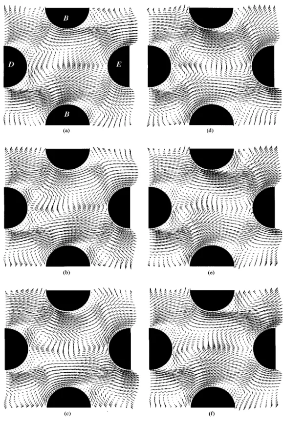
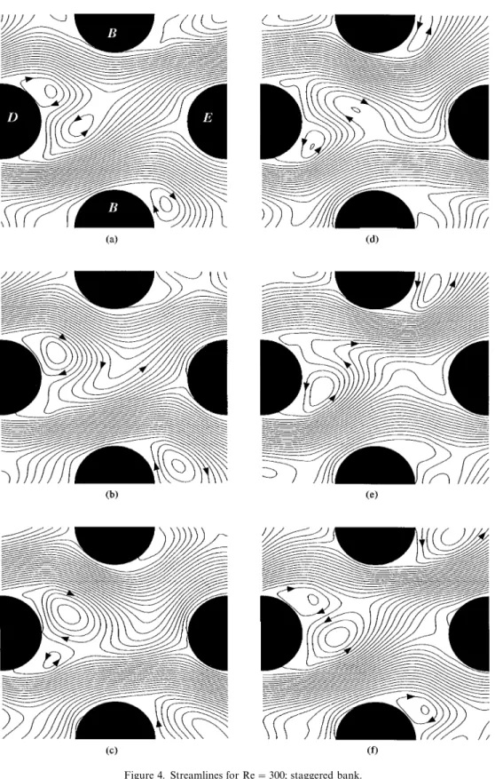
Figure 3 shows a sequence of six plots of velocity vectors, and illustrates the time-dependent #ow patterns in the central zone [Figure 1(b), b-b@] over one complete cycle at Re"300 for the rotated square tube bank. Figure 4 shows streamlines, Figure 5 pressure contours, and Figure 6 temperature contours over the same sequence. Figures 7}10 show similar plots of velocity vectors, streamlines and temperature contours for the upstream module of the in-line bank [Figure 1(a)] at Re"300.
Figure 2. Response to feedback mechanism.
2.2. MONITORPOINTANDCONVERGENCEDATA
Figure 11 shows values of the crosswise v-velocity at a monitor point located midway between cylinders A and B [Figure 1(b)] as a function of time at various Re values for the rotated square bank. Figure 12 is a similar plot at various applied frequencies, while Figure 13 shows the in#uence of the amplitude of the applied disturbance: the motion is independent of the magnitude and frequency of the applied disturbance. Figure 14 shows the in#uence of the applied frequency on the transient motion for the in-line bank. Traces of monitor point, crosswise velocity are displayed together with the initial applied disturbance for Sh0 of 0)05, 0)1, 0)2 and 0)5. The monitor point is located halfway between cylinders B and C in Figure 1(a). Table 1 shows values of Sh for both in-line and staggered geomeries as the number of time-steps and sweeps is increased.
2.3. DRAGANDHEATTRANSFER
Tables 2 and 3 are summaries of results for stimulated and spontaneous behaviour, respectively, within the rotated square tube bank; Table 4 gives data for the in-line geometry. All values are averaged over the last half of each simulation. The"nal frequency fis calculated from the v-velocity at the monitor point. The quantity fqx is the fraction of a cycle by which the upstream transient leads the value at the subsequent row; this is computed from the v-values at two monitor points. The Euler number Eu is de"ned as the normalized mean pressure di!erence between two rows:
Eu"DpN308 1
2ou2m. (13)
Both the time-average valuek and the sample standard deviation p are given in Tables 2}4. Lift and drag coe$cients cL and cD are de"ned as the net forces due to lift and drag per
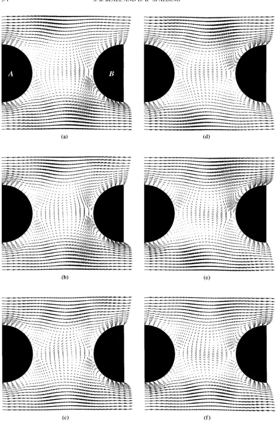
Figure 3. Velocity vectors for Re"300; staggered bank. 730 S. B. BEALE AND D. B. SPALDING
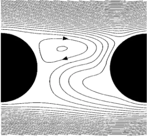
Figure 4. Streamlines for Re"300; staggered bank.
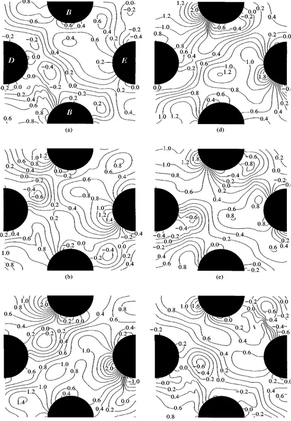
Figure 5. Pressure contours for Re"300; staggered bank. 732 S. B. BEALE AND D. B. SPALDING
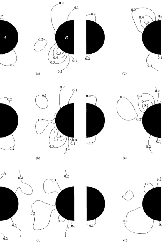
Figure 6. Temperature contours (3C) for Re"300; staggered bank.
Figure 7. Velocity vectors for Re"300; in-line bank. 734 S. B. BEALE AND D. B. SPALDING
Figure 8. Streamlines for Re"300; in-line bank.
Figure 9. Pressure contours for Re"300; in-line bank. 736 S. B. BEALE AND D. B. SPALDING
Figure 10. Temperature contours (3C) for Re"300; in-line bank.
Figure 11. E!ect of Re for Sh0 "0)2; staggered bank.
Figure 12. E!ect of f0 for Re"300; staggered bank. 738 S. B. BEALE AND D. B. SPALDING
Figure 13. E!ect of <0 for Re"300, Sh0 "0)2; staggered bank.
Figure 14. E!ect of f0 for Re"300; in-line bank.
TABLE1
Solution independence studies, Re"300
Type Sweeps Time-steps Sh
In-line square 40 480 0)0891 In-line square 40 960 0)0920 In-line square 100 960 0)0925 In-line square 100 1960 0)0933 Rotated square 40 320 0)289 Rotated square 40 640 0)353 Rotated square 100 640 0)358 Rotated square 100 1280 0)356 TABLE2
Staggered geometry, stimulated response, Sh
0"0)2, <0"0)2um Re Sh fq x Eu cD cl Nu (k) (k) (k) (p) (k) (p) (p) (k) (p) 30 * * 0)92 0)06 2)88 0)05 0)017 6)4 0)1 100 0)27 0)73 0)57 0)06 1)88 0)17 0)047 8)9 0)3 300 0)35 0)89 0)37 0)18 1)73 0)31 0)062 15)5 1)1 1000 0)31 0)76 0)25 0)19 1)61 0)32 0)050 30)0 1)9 3000 0)26 0)82 0)16 0)20 1)32 0)33 0)027 56)6 2)9 TABLE3
Staggered geometry, spontaneous response, no lateral feedback, <0"0
Re Sh fqx Eu cD cl Nu (k) (k) (k) (p) (k) (p) (p) (k) (p) 30 * * 0)93 0)00 2)87 0)00 0)001 6)3 0)0 100 0)22 * 0)61 0)02 1)92 0)06 0)007 9)1 0)3 300 0)35 0)95 0)25 0)22 1)69 0)47 0)061 15)5 1)0 1000 0)30 0)75 0)02 0)24 1)51 0)45 0)056 29)6 2)4 3000 0)31 0)75 0)02 0)25 1)34 0)42 0)033 54)9 3)7 TABLE4 In-line geometry, stimulated response, Sh
0"0)1, <0"0)2um Re Sh fq x Eu cD cl Nu (k) (k) (k) (p) (k) (p) (p) (k) (p) 100 0)09 0)44 0)317 0)018 1)313 0)046 0)066 3)92 0)069 300 0)09 0)41 0)171 0)055 0)747 0)122 0)051 6)73 0)47 1000 0)12 0)55 0)104 0)130 0)630 0)214 0)077 17)4 2)2 3000 0)10 0)52 0)193 0)404 1)048 0)553 0)044 40)8 3)9
Figure 15. cp versus h for Re"300, Sh0"0)2, <0 "0)2um; in-line bank. projected area, normalized with respect to12ou2m and computed as follows:
cD"1t
P
t 1 ou2mAP
n 0 (p cosh#qwsinh)dh#P
2n n (p cosh!qwsinh)dhB
dt, (14) and cL"1tP
t 1 ou2mAP
n 0 (!p sinh#qwcosh)dh!P
2n n (p sinh#qwcosh)dhB
dt, (15) whereh is the angle from the front of the cylinder. The average Nusselt number Nu is de"ned by Nu"h1 d k , (16) where h1 " 2nqRwP
2n 0 (¹w!¹1b) dh , (17) and qRwis the constant wall-heat#ux, ¹w the wall temperature and ¹Mb the time-average bulk temperature in the upstream inter-tube space for the tube under consideration.
Figures 15 and 16 show the instantaneous pressure coe$cient cp for both in-line-square and rotated-square geometries, as a function of the angle, h, from the front edge of the
Figure 16. cp versus h, for Re"300, Sh0"0)1, <0 "0)2um; staggered bank. cylinder. The local-pressure coe$cient is de"ned as
cP"1!pN (0)!p(h)12ou2m , (18)
where pN (0) is the time-average pressure at h"03. The curves a}f in Figures 15 and 16 correspond to the data shown for the eight captions in Figures 3}10. Figure 17 shows the friction coe$cient cf against h de"ned as
cf"$12ouqw2m, (19)
where the shear stress is computed from the velocity gradient at the wallqw"kRu/Rn, and the sign of cf is taken to be positive for 034h41803 and negative for 18034h43603. Figure 18 shows the instantaneous local Nusselt number for the in-line bank. The local Nu is based on an instantaneous local heat transfer coe$cient h"qRw/(¹w!¹b) and nor-malized with respect to the long-term, time-average value Nu as de"ned in equations (16) and (17).
3. DISCUSSION 3.1. DESCRIPTION OF THEFLOWFIELD
3.1.1. Rotated-square bank
Figures 3(a}f) and 4(a}f) show a sequence of velocity vectors and streamlines for the rotated-square tube bank at Re"300. (a) A clockwise vortex has developed behind the 742 S. B. BEALE AND D. B. SPALDING
Figure 17. cf versus h, for Re"300, Sh0"0)1, <0 "0)2um; in-line bank.
Figure 18. Nu versush, for Re"300, Sh0"0)1, <0"0)2um; in-line bank.
top-rear side of the upstream cylinder D; below and downstream of this "rst vortex, a second counterclockwise vortex can also be seen. (b) The clockwise vortex grows in the presence of the favourable shear layer (rate-of-deformation gradient) and increases the angular momentum. (c) This increases the size of the vortex, and displaces it back into the wake, to the rear of cylinder D. As the vortex moves across the centreline, it encounters an adverse shear layer (on the lower side of the cylinder) which entrains it, and decreases the angular momentum. The opposing streams result in the birth of a new counterclockwise vortex at a location between the existing vortex and the main stream below. (d) The clockwise vortex is now displaced downstream, and the new counterclockwise vortex begins to grow in the presence of the favourable shear layer behind the rear-lower side of the cylinder. The clockwise vortex moves along with the#ow, and (e) is destroyed as it passes through the minimum cross-section of the subsequent row B-B. By (f) the cycle is complete. The wake behind cylinder D is S-shaped, and switches back and forth in a sinuous fashion because alternate quantities of clockwise and counterclockwise momentum are being imparted. Two rows downstream, the#ow bifurcates at a point towards the front of cylinder E. The location of this point moves as the fast-moving free streams stick to alternate sides of cylinder E. This situation results in a Coanda-like e!ect. The large-scale, symmetry-breaking bifurcation thus represents a fundamentally di!erent solution to the perturbation problem than that obtained from calculations which presume the motion may be treated as one which is steady.
3.1.2. In-line bank
Figures 7 and 8 show the transient#ow regime for the in-line bank at Re"300. The motion is similar in many ways, but also di!erent from that in the staggered geometry. The streamline plots in Figure 8 show that a counterclockwise vortex has formed initially in the space between cylinders A and B. This vortex moves into the central inter-tube zone, and thus spawns a small clockwise vortex behind the upstream cylinder, as described above. The new vortex expands to"ll the inter-tube region and displaces the original counterclock-wise vortex which decays as a result of friction forces. The clockcounterclock-wise vortex "lls the entire inter-tube space and detaches from behind the cylinder, and thereby induces the formation of a counterclockwise vortex, and the sequence repeats itself.
Comparison of the vector"elds in Figure 3 to those in Figure 7 reveals that the transient motion is much less pronounced for the in-line geometry than for the staggered bank. For the former case, the wake is relatively quiescent because of the shading e!ect of subsequent rows. Inspection of animation sequences revealed that as each vortex develops, #uid particles near the wall enter the inter-tube zone from the free stream. As the vortex is dissipated downstream,#uid particles are ejected back out into the main stream, so there is momentum exchange between the vortex and the fast-moving free stream. The free stream undulates with the direction of rotation of the vortices, i.e., there is a shear-layer instability. The single attachment point oscillates with the#ow. Calculations which presume steady, fully developed periodic#ow predict two symmetric reattachment points on either side of the cylinder (Beale & Spalding 1998). For s/d"2, only one vortex is ever fully formed in the inter-tube space, although up to three partially formed vortices of opposite spin may be present for a very short period of time.
3.1.3. General remarks
For both in-line and staggered banks, the#ow "elds were found to be qualitatively similar over a wide Re range. The size of velocity vectors within the vortex increased with Re, even 744 S. B. BEALE AND D. B. SPALDING
though the streamline plots were relatively similar, and only minor di!erences in size of vortices, number present, residence time, etc., were noted over a wide Re range. Comparison of animated sequences of the present results with the 16 mm"lm clip of Weaver & Abd-Rabbo (1984) revealed the numerical work to be physically realistic, as veri"ed indepen-dently by others (PamK doussis 1994). It appears that calculated vortices may survive for a shorter time than did those observed in#ow visualization studies, perhaps because of numerical di!usion associated with the spatial hybrid scheme and the use of the "rst-order temporal discretization in equation (4). Also, no two vortices are precisely the same in nature, whereas the numerical calculations generate a highly repeatable, periodic motion. The curves shown in Figures 4 and 8 are streamlines*not streak lines like those obtained in experimental work. Tests showed that for larger values of s/d the behaviour is more like that of single cylinders, in that several vortices coexist in the wake, in a way consistent with the results of Wallis (1939).
Inspection of Figures 6 and 10 reveals that the formation of the vortices has a signi"cant e!ect on the temperature "eld. Consider, for example, Figure 10. As each vortex becomes fully developed, it detaches and occupies the central zone between the two cylinders. At this time, there is a strong cross-#ow at the front of the downstream cylinder B. The e!ect is to pull (cold)#uid at the free-stream temperature in, and across the (hot) downstream cylinder B. This results in a trough in the temperature"eld near the lower front side of cylinder B [Figure 10(b)]. This sharp temperature gradient quickly collapses as the vortex loses angular speed and is dissipated on the lower front side of cylinder B [Figure 10(c)]. As the subsequent clockwise vortex"lls the inter-tube space, another tongue of cold #uid is drawn from the attachment point on the upper side of cylinder B [Figure 10(d, e)]. Thus, there is substantial gross mixing of free-stream and inter-tube#uids due to the alternate swirling motion of the vortices which results in more e!ective heat transfer.
3.2. INDEPENDENCE OFSOLUTION
3.2.1. Staggered bank
Inspection of the upstream monitor-point v-values in Figure 11 shows that at Re"30, the disturbance is damped out. For Re"100 the transient maintains itself, as is just apparent from the end of the trace in Figure 11 (NB : the downstream response leads by 240 time-steps). As Re is increased, the amplitude of the v-#uctuations increases to approxim-ately 0)5um at Re"300. At a su$ciently high Re value a de"nite &&transistor'' or &&triode'' e!ect is observed: small lateral perturbations are ampli"ed under the action of the main #ow, so the downstream oscillations are much larger than the upstream disturbance*i.e., there is a fundamental instability to lateral perturbations of the symmetry line. A stable periodic behaviour is eventually established with no gain, by means of a back-substitution process. Figures 12 and 13 show the transient to be relatively una!ected over a wide range by either the frequency f0 or the magnitude <0 of the initially applied disturbance. Note that oscillations arose spontaneously with <0"0. In fact, for the staggered geometry, spontan-eous oscillations arose regardless of whether or not the explicit lateral back-substitution mechanism was invoked. This suggests that these numerical results are a reasonable facsimile of the actual#ow within the passages of a rotated square tube bank.
3.2.2. In-line bank
For the in-line square bank initially applied, spanwise oscillations were ampli"ed under the action of the main #ow, especially at higher Re values, although this e!ect was less
pronounced than for the rotated square geometry. For Re"30, no periodic behaviour was observed. At higher Re, the same e!ect as that described above was noted. For the in-line tube bank, however, the excitation frequency appears to a!ect the "nal outcome of the calculations (Figure 14). When the initial frequency f0 was applied such that 0)054Sh040)5, "nal values of Sh lay in a band between approximately 0)1 and 0)2. At high frequency (Sh0"0)5), the response degenerates to a much lower frequency. This suggests that if the calculations were continued for a very long time, the#ow may ultimately converge on a natural frequency independent of the initially applied signal. The results of the numerical calculations may not necessarily correspond to the naturally occurring oscillations in an in-line square tube bank, but the downstream response to a stimulated perturbation would be similar to that shown in Figures 7}10. For very widely spaced in-line banks, it was possible to obtain transient behaviour spontaneously. It is believed that the in#uence of the amplitude is primarily on the number of time-steps required to reach a repeatable periodic behaviour. In experimental work on an in-line square array with s/d"1)5, Price et al. (1991) noted that the oscillation of the dividing line would build up to a maximum, then decay to a minimum before building up again. This ubiquitous behaviour is consistent with the results of Figure 14, and could indicate the presence of a beat frequency associated with multiple Sh, the e!ects of large-scale free-stream turbulence, or both.
3.2.3. General remarks
The basis for the present method is the application of a harmonic excitation. The iterative feedback mechanism emulates the row-by-row development of the oscillatory response, which would occur in a large-scale heat exchanger. The choice of the initial and boundary conditions may a!ect some aspects of the process, and limitations of computational resources necessitate calculations be terminated sooner than preferred; however, the results of this study provide interesting and meaningful insight into the complex nature of the#ow in the passages of tube banks.
The downstream #ow is extremely responsive to any initial excitation if it is applied across the lateral boundary (Figure 1, A-B). Fluctuations applied along the inlet (across a-a@) are damped out quickly. When downstream values were back-substituted, it was again the lateral, spanwise terms that were dominant. The streamwise (in#ow) values were also important, but subordinate. The calculations suggest that the staggered con"guration is fundamentally more prone to transient behaviour than the in-line bank, and that it is easier to generate instabilities for a larger pitch-to-diameter ratio s/d. This result is consistent with experimental#ow visualization studies.
Unlike external transient#ow past simple blu! bodies, the correct prescription for the boundary conditions is not obvious. Several combinations of initial and boundary condi-tions were considered prior to those that were adopted here: for example, doubly periodic conditions where qx"0 and qy"0 (Pruitt et al. 1990; Stuhmillar et al. 1988). Their use resulted in the transient motion being completely damped out, an outcome consistent with the laminar-#ow results of Stuhmillar et al. (1988).
For the staggered geometry, vortex shedding could be induced passively without the disturbance-feedback mechanism, and a comparison of the results of Tables 2 and 3 reveals broad agreement in performance measures for the most part, regardless of whether the mode of excitation was passive or active. The active excitation method is nevertheless recommended for all geometries: in the absence of an explicit overall lateral-momentum constraint, the #ow tends to wander at low Re (residual drift), while overall stability is 746 S. B. BEALE AND D. B. SPALDING
di$cult to control at high Re. The explicit prescription for lateral momentum is valid, as sources of mass and momentum do emanate from these boundaries: i.e., for a signi"cant fraction of the cycle they are upstream. This prescription is also suitable for steady, fully developed oblique (diagonal) cross-#ow. The downstream pressure boundary condition based on potential #ow theory is consistent with classical boundary-layer theory and generates a reasonable solution to the #ow-"eld problem. Some local distortion of the pressure"eld due to the concave shape of velocity pro"le was observed near the walls, but this does not a!ect the upstream results signi"cantly. Forward substitution of upstream pressure pro"les downstream (Beale & Spalding 1998) is a plausible alternative in theory, but since qx is not known a priori, it will not correspond to a discrete number of computational time-steps. The impact of the premise that streamwise di!usion is subordi-nate to convection or inertia at the inlet is small.
Lateral di!usion was accounted for everywhere. For the in-line case, no reverse #ow occurred at either the inlet or the outlet. For the staggered geometry, the module used to calculate performance measures was located one-half pitch downstream from the inlet. Whether the assumption that the lateral transients are in phase u(x, y#sy, t)"u(x, y, t), qy"0 is, however, a point for discussion: the alternate vortex-shedding patterns described in this paper are consistent with those observed experimentally; other modes have also been observed however, e.g., symmetric vortex shedding at low Re in a rotated-square array (Price et al. 1991) and alternate vortex shedding in an in-line bank with adjacent streams out of phase fqy"12 (Ziada & OengoKren 1992). Attempts to generate the latter behaviour numerically by the construction of two complete modules in the crosswise y direction degenerated to the periodic case fqy"0. Lateral #uctuations can only arise and be propagated in the presence of minor di!erences in velocity or pressure between adjacent modules, so the argument that both u(x, y#sy, t)"u(x, y, t) and p(x, y#sy, t)"p(x, y ,t) exactly is seemingly paradoxical. Indeed, experimental#ow visualization studies reveal that no two vortices are ever precisely the same. Nevertheless, if adjacent modules in both streamwise and crosswise directions were not in phase, the instantaneous bulk velocity would vary from module to module, which suggests the presence of an inherently 3-D (and possibly random) component to the motion.
Beale (1993a) contained comparisons of the results of calculations for steady, fully developed 2-D#ow and steady, fully developed 3-D cross-#ow in cylinders with diameter dand length l ("n-and-tube heat exchanger). The results suggested that at low Re values the 3-D pressure loss and heat transfer factors di!er negligibly from the 2-D cases, provided l: d 510 : 1. The results also showed that at higher Re values, complex 3-D#ow patterns do in fact arise: in addition to the wake vortices at the back of each cylinder, a downward motion at the front of each cylinder results in a horseshoe vortex. In a staggered bank, these two#ow phenomena are located almost side by side, and a complex interaction is observed at a su$ciently high Re value. This interaction may ultimately lead to the breakdown of the steady periodic behaviour and the resulting generation of turbulence. Detailed transient 3-D studies are beyond the scope of this paper; the need for such studies in the future, however, is readily apparent.
Convergence studies revealed some di!erences in the magnitude of the #uctuating velocity component; however Table 1 also reveals that Sh values obtained on the basis of twice the time-steps and 2)5 times the sweeps per time-step, agreed to within 0)7% (staggered) and 1)3% (in-line). The use of coarser grids was found to damp out the oscillatory behaviour, while the use of grids"ner than the 80]160 cells adopted for this study could not be considered because of"nite computer limitations. It is worth noting that the in-line grid was orthogonal, whereas the staggered geometry necessitated the construc-tion of a nonorthogonal mesh.
3.3. PRESSUREDISTRIBUTION
Observed pressure"elds were quite complex (see Figures 5 and 9), and quite di!erent from those observed from potential or steady-viscous#ow calculations (Beale & Spalding 1998; Beale 1993a, b). A pressure maximum occurs near the bifurcation point, minima occur at the sides of the cylinder (nearh"903), and multiple extrema arise in the inter-tube space.
Within the wake, the u-component oscillates at 2f since u varies with the magnitude of the v-#uctuations and in#uences the pressure trace, which is either at f, 2f or a combination, depending on the strength of the two velocity components. The crosswise v-velocity oscillates in a repeatable sinuous fashion, while the magnitude of the streamwise u-#uctuations tends to increase with Re and become erratic, so that by Re"3 000 the pressure #uctuations also increase and become erratic and unstable. With streamwise frequency twice the crosswise frequency, Sh based on a wake value of u is anisotropic. Several experimental workers (Chen 1978; Fitzpatrick 1986; Price et al. 1987; Weaver & Abd-Rabbo 1986; Ziada et al. 1989, 1992) have noted the existence of multiple Sh. It is interesting to speculate on the existence of higher harmonics, interference e!ects or beats, and the in#uence of the erratic pressure #uctuations on the generation of random free-stream turbulence.
Figure 15 shows cp(h) for the in-line square bank (same sequence of events as in Figure 7). A single pressure maximum is associated with the establishment of the attachment point at the front side of the cylinder. The maximum rises and falls on opposite sides of the cylinder. Further downstream, the pressure minima are also substantially a!ected by the transient nature of the#ow. Signi"cant #uctuations in cp are observed around the entire periphery of the cylinder. Figure 16 exhibits cP against h for the rotated square tube bank (same as in Figure 3). The results are qualitatively similar, although the transient #uctuations in cP around the periphery are signi"cantly larger than for the in-line square case, which re#ects the more vigorous motion. A rise in pressure is again associated with the establish-ment of the attachestablish-ment point at one or other side of the front of the cylinder. The pressure minima at the sides of the cylinder#uctuate. Some minor discontinuities at the leading and trailing edges are due to grid-related e!ects. The presence of an overall favourable pressure gradient in the streamwise direction Dp308/sx would tend to impede vortex formation and suppress such phenomena to higher Re in tube banks than in single cylinders. The pressure "eld may also assist transience: for potential #ow in staggered banks (Beale 1993a, b), there is a checkerboard pressure distribution with global maxima ath"0 and 1803, and minima ath"90 and 2703 on the cylinder wall. A saddle point occurs in the wake region at the next o!set row [at the mid-point between D and E, Figure 1(b)], which suggests that a state of metastable equilibrium exists whereby any tendency for lateral wake switching in staggered banks, and jet instabilities in in-line banks, would be reinforced.
3.4. FREQUENCY ANDDRAG
3.4.1. Staggered bank
Tables 2 and 3 show that for the staggered tube bank, Sh values ranged between 0)22 and 0)35, with the mean values near 0)3. Z[ukauskas et al. (1988) suggest these to be of the order of 0)34, whereas the Weaver et al. (1986) correlation, based on an interpretation of an Owen (1965) hypothesis, indicates a value of Sh"0)33. Comparison of Tables 2 and 3 shows a consistency in Sh values; for actively induced excitation, calculated values range between !21% and #6% of the value in Owen (1965), while the self-induced values range between !36% and !6%. As Re increases, the mean value of Eu decreases, while the periodic 748 S. B. BEALE AND D. B. SPALDING
component becomes substantially larger. At high Re values, the#uctuating component of the pressure"eld is very large compared to the steady-state value. This a!ects both Eu and cD, which become erratic. On the other hand, cL oscillates in a stable, sinusoidal-like manner. Time-average and#uctuating components of Nu increase with Re, although the latter is a much smaller fraction of the mean value than was observed for Eu or cD, as indicated by the ratiop/k. Tables 2 and 3 reveal agreement to be much better than Eu values when the cases of stimulated and spontaneous vortex shedding are compared: because of the length of time required to make the numerical calculations, only a few cycles were considered in this study. Quantitative measures of performance should therefore be con-sidered as only approximate.
3.4.2. In-line bank
Table 4 reveals Sh calculations by the authors ranging from 0)09 at low Re values, to about 0)12 at Re"1000. Only 6}8 cycles were used to compute these values, and while they should be considered approximate, they are of the same order as the applied disturbance. A variety of experimental data have been gathered on Sh for in-line tube banks. Z[ ukauskas et al. (1978) suggest that for s/d"2, Sh"0)24 at Re"500. This value is in broad agreement with the values near 0)25}0)26 extrapolated from Weaver et al. (1986), Z[ukaus-kas et al. (1988), and also Chen (1968) and Fitz-Hugh (1973). The latter sets of results are known to be in the acoustic range, and are therefore not considered appropriate for comparison with the present work. Rae & Wharmby (1987) suggest a lower value for Sh, around 0)155, for s/d"2, in the nonacoustic vortex-shedding regime. These lower Sh values were independently validated by Ziada & OengoK ren (1992) for a 1)75]2)25 in-line bank, in the nonacoustic regime. The present authors' values are thus comparable to those of Rae & Wharmby (1987), but are about 20}40% lower. Weaver et al. (1986) show the very substantial disparities in measured experimental values of Sh reported by the various authors for s/d"1)5 and 2. The disparities are attributed to the presence of multiple Sh. The amplitude of the lateral v-#uctuations was observed to be quite large: for Re'300, the peak oscillations can be up to 50% of the bulk streamwise velocity. Above this value, v-#uctuations remained fairly constant, repeatable and sinusoidal-like. The lateral #uctuations tend to be stable at high Re but erratic at low Re, while the converse is true for the streamwise and pressure #uctuations. The magnitude of streamwise u-velocity and pressure#uctuations increased in strength over the entire Re range, with the pressure signal becoming less stable at higher Re. The quantity fqx in Table 4 represents the di!erence between the upstream and downstream crosswise v-velocity #uctuations, expressed as a fraction of a cycle. It can be seen that the upstream transient precedes the downstream value by between 0)44 and 0)55, i.e., the oscillations are close to a half-cycle (or 1803) out of phase regardless of Re. This trend is consistent with the observations of experimental workers (Weaver & Abd-Rabbo 1985; Ziada & OengoK ren 1992).
Time-average Eu converged to a value close to the steady-state value in the low Re range (Beale 1993a). As Re increases the mean value decreases, while the periodic component becomes substantially larger. At high Re, the#uctuating component of the pressure "eld is large compared to the steady-state value: at times, there is even an instantaneously favourable pressure gradient. (The apparent increase in Eu at Re"3 000 is observed because the simulation is of insu$cient length, and the Re range for which free-stream turbulence can be ignored is exceeded.) Oscillations of the lift coe$cient were observed to be sinusoidal-like, with the peak cL value at Re"1000. Overall, cD values were observed to decrease with an increase in Re. The#uctuating component of cD is large compared to the mean value.
Figure 17 shows cf(h) for the in-line bank. The large negative values of cf between h"0 and 453 indicate the strength of the shear-inducing vortices. Values of cf"0 give the location of the attachment and separation points, one of which is apparent at any given moment, unlike the steady case where there are two of each. These results illustrate the fundamental di!erence between the results of the calculations performed here, and solutions based on the premise of steady#ow (Beale & Spalding 1998). With regard to heat transfer, both time-average and#uctuating components of Nu increase with Re, but the latter is a much smaller fraction of the mean value than was observed for Eu or cD. Values of Nu are higher than those observed for steady#ow as a result of the increased mixing of the #uid. Nu is calculated on the assumption that the upstream bulk#uid temperature is constant: in fact, the bulk temperature also#uctuated at higher Re, but these #uctuations were minor. Figure 18 shows that there is substantial time variation in the local Nusselt number distribution for the in-line geometry. Heat transfer is a global maximum at the front of the cylinder near the attachment point. The heat transfer transient lags slightly behind the shear stress transient. For the staggered bank, the maximum oscillates in a zone towards the front of the tube, unlike the results of steady-state calculations which predict a stationary maximum ath"03.
4. CONCLUSIONS
Both in-line and staggered tube banks exhibit transient behaviour for Re'100 whereby spanwise perturbations are ampli"ed, while at lower Re they decay. For the in-line geometry, an explicit excitation and feedback mechanism was required to generate a transi-ent, fully developed periodic motion. Vortices were generated and shed from alternate sides of the cylinders. This phenomenon resulted in a shear-layer instability between the wake and the rapidly moving free stream. Only one fully formed vortex was present in the inter-tube space at any given time. The streamwise phase di!erence was approximately 1803. Only one mode of transient behaviour was observed: when multiple lateral modules were considered, the#ow always stabilized to the in-phase condition. Observed Sh were dependent on the initial excitation frequency f0. The nondimensional numbers Eu, Nu, cP, cD and cL all displayed a strong transient behaviour substantially di!erent from that obtained from numerical calculations for steady-periodic#ow. The Euler number Eu and drag coe$cient cD displayed very large #uctuations about the mean, while heat transfer appeared to be enhanced as a result of mixing of the #uid. Both #uid #ow and scalar transport in tube banks were substantially a!ected by transient e!ects for Re5100. In the case of pressure drop and drag, large #uctuations were observed. Skin friction and heat transfer are also substantially di!erent from the results of numerical calculations for steady, fully developed periodic#ow. Strouhal numbers ranged between 0)09 and 0)12, or !20 to !40% below experimental values.
In the staggered tube bank, alternate vortex-shedding and wake-switching e!ects were observed. These were shown to be essentially independent of the disturbance over a range of applied amplitudes and frequencies; moreover, it was shown that the transients could develop spontaneously. The transient nature of the motion has a large impact on the value of pressure-related quantities such as cp and Eu. Strouhal numbers were in reasonable agreement with experimental data; for the staggered geometry, Sh values ranged between 0)26 and 0)35, or from !21 to #6% of measured values.
The nature of the problem is such that the#ow-"eld calculations are in#uenced by the grid, boundary conditions and numerical scheme. The quantitative results of this numerical experiment should therefore be considered as only approximate, particularly for the in-line 750 S. B. BEALE AND D. B. SPALDING
square geometry. Nonetheless, much insight has been gained into the nature of the excitation mechanism and response, and the resultant e!ects upon transport phenomena within the passages of tube-bank heat exchangers. The main conclusion of this study is that the#ow is fundamentally unstable to lateral perturbations. As a result of this triode-like e!ect, small symmetry-breaking oscillations are ampli"ed and result in large pressure #uctuations acting on the walls of downstream tubes. It is generally accepted now that, other than#uidelastic instabilities, the main causal mechanisms for #ow-induced vibrations are vortex shedding, acoustic coupling and turbulent bu!eting. One advantage of numerical analysis is that the e!ects of each of the phenomena may be isolated and investigated independently. Here only the former was considered: a majority of heat exchangers operate at intermediate Re values, where the presence of turbulence in the free-stream passages in#uences the #ow. It is important that future modelling research address the subject of turbulent bu!eting, in the regime where the characteristic length of the eddies is large (Owen 1965), since this subject has received little attention to date. It is to be anticipated that future advances in mathematical modelling will lead to more accurate computer-based calcu-lations, which will enhance traditional empirical techniques, and increase knowledge and con"dence in the design of heat exchangers.
REFERENCES
ABD-RABBO, A. & WEAVER, D. S. 1986 A#ow visualisation study of #ow development in a staggered tube array. Journal of Sound and <ibration 106, 241}256.
ANTONOPOULOS, K. A. 1979 Prediction of#ow and heat transfer in rod banks. Ph.D. Thesis, Imperial College, University of London.
BEALE, S. B. 1993a Fluid #ow and heat transfer in tube banks. Ph.D. Thesis, Imperial College, University of London.
BEALE, S. B. 1993b Potential #ow in in-line and staggered tube banks. NRC Technical Report IME-CRE-TR-006. National Research Council of Canada, Ottawa, Canada.
BEALE, S. B. 1997a Tube banks, cross#ow over. In International Encyclopedia of Heat and Mass ¹ransfer(eds G. F. Hewitt, G. L. Shires, and Y. V. Polyshaev), pp. 1188}1193. New York: CRC Press Inc.
BEALE, S. B. 1997b Tube banks, single-phase heat transfer in. In International Encyclopedia of Heat and Mass ¹ransfer(eds G. F. Hewitt, G. L. Shires, and Y. V. Polyshaev), pp. 1188}1193. New York: CRC Press Inc.
BEALE, S. B. & SPALDING, D. B. 1998 Numerical study of#uid #ow and heat transfer in tube Banks with stream-wise periodic boundary conditions. ¹ransactions of the CSME 22, 4, 397}416.
BORTHWICK, A. 1986 Comparison between two "nite-di!erence schemes for computing the #ow around a cylinder. International Journal for Numerical Methods in Fluids 6, 275}290.
BRAZA, M., CHASSAING, P. & MINH, H. H. A. 1986 Numerical study and physical analysis of the pressure and velocity"elds in the near wake of a circular cylinder. Journal of Fluid Mechanics 165, 79}130. CARETTO, L. S., GOSMAN, A. D., PATANKAR, S. V. & SPALDING, D. B. 1972 Two calculation procedures for steady, three-dimensional #ows with recirculation. In Proceedings of the 3rd International Conference on Numerical Methods in Fluid Mechanics. Lecture Notes in Physics, Vol. 2, pp. 60}68. Berlin: Springer-Verlag.
CHANG, K. S. & SONG, C. J. 1990 Interactive vortex shedding from a pair of circular cylinders in a transverse arrangement. International Journal for Numerical Methods in Fluids 11, 317}329. CHEN, S. S. 1978 Cross#ow-induced vibrations of heat exchanger tube banks. Nuclear Engineering and
Design 47,67}86.
CHEN, Y. N. 1968 Flow-induced vibration and noise in tube-bank heat exchangers due to von Karman streets. ASME Journal of Engineering for Industry 90, 134}146.
EATON, B. E. 1987 Analysis of laminar vortex shedding behind a circular cylinder by computer-aided #ow visualization. Journal of Fluid Mechanics 180, 117}145.
FITZ-HUGH, J. S. 1973 Flow-induced vibration in heat exchangers. In ;KAEA/NP¸ International Symposium on <ibration in Industry, Keswick, U.K. Paper No. 427, pp. 1}17.
FITZPATRICK, J. A. 1986 A design guide proposal for avoidance of acoustic resonances in in-line heat exchangers. ASME Journal of <ibration, Acoustics, Stress and Reliability in Design 108, 296}299. UNSTEADY FLOW IN TUBE BANKS 751
GRESHO, P. M., STEVENS, T., LEE, R. L., & UPSON, C. D. 1984 A modi"ed "nite element method for solving the time-dependent, incompressible Navier}Stokes Equations. Part 2: Applications. International Journal for Numerical Methods in Fluids 4,619}640.
HARLOW, F. H., & WELCH, J. E. 1965 Numerical calculation of time-dependent viscous incompressible #ow of #uid with free surface. Physics of Fluids 8, 2182}2189.
JOHNSON, A. A., TEZDUYAR, T. E. & LIOU, J. 1993 Numerical simulation of#ows past periodic arrays of cylinders. Computational Mechanics 11, 371}383.
JORDAN, S. K., & FROMM, J. E. 1972 Oscillatory drag, lift, and torque on a circular cylinder in a uniform #ow. Physics of Fluids 15, 371}376.
LECOINTE, Y. & PIQUET, 1984 On the use of several compact methods for the study of unsteady incompressible viscous#ow round a circular cylinder. Computers and Fluids 12, 255}280. LEFEUVRE, R. F. 1973 Laminar and turbulent forced convection processes through in-line tube banks.
Ph.D. Thesis, Imperial College, University of London.
NG, C. W., CHENG, V. S. Y. & KO, N. W. M. 1997 Numerical study of vortex interactions behind two circular cylinders in bistable#ow regime. Fluid Dynamics Research 19, 379}409.
OWEN, P. R. 1965 Bu!eting excitation of boiler tube vibration. I.Mech.E. Journal of Mechanical Engineering Science 7,431}439.
PAIG DOUSSIS, M. P. 1982 A Review of#ow-induced vibrations in reactors and reactor components. Nuclear Engineering and Design 74,31}60.
PAIG DOUSSIS, M. P. 1994 Personal communication.
PATANKAR, S. V. 1980 Numerical Heat ¹ransfer and Fluid Flow. Hemisphere: New York.
PATANKAR, S. V., & SPALDING, D. B. 1972 A calculation procedure for heat, mass, and momentum transfer in three-dimensional parabolic#ows. International Journal of Heat and Mass ¹ransfer 15,1787}1806.
POLAK, D. R. & WEAVER, D. S. 1995 Vortex shedding in normal triangular tube arrays. Journal of Fluids and Structures 9,1}17.
PRICE, S. J., PAIG DOUSSIS, M. P., MACDONALD, R. & MARK, B. 1987 The#ow-induced vibration of a single #exible cylinder in a rotated square array of rigid cylinders with pitch-to-diameter ratio of 2)12. Journal of Fluids and Structures 1,359}378.
PRICE, S. J., PAIG DOUSSIS, M. P., MUREITHI, W. N. & MARK, B. 1991 Flow visualization in a 1)5 pitch-to-diameter rotated square array of cylinders subject to cross-#ow. In Flow Induced <ibrations, Vol. 1, pp. 243}252, London: I.Mech.E.
PRUITT, J. M., HASSAN, Y. A., & STEININGER, D. A. 1990 Large eddy simulation of turbulent#ow in a tube bundle. Paper presented at the =inter Annual Meeting of the ASME, Dallas, TX, U.S.A. RAE, G. J. & WHARMBY, J. S. 1987 Strouhal numbers for in-line tube arrays. In Proceedings of International Conference on Flow-induced <ibrations, Bowness-on-Windermere, U.K., pp. 233}242. SA, J-Y., & CHANG, K-S. 1991 Shedding patterns of the near-wake vortices behind a circular cylinder.
International Journal for Numerical Methods in Fluids 12,463}474.
SPALDING, D. B. 1972 A novel"nite-di!erence formulation for di!erential expressions involving both "rst and second derivatives. International Journal for Numerical Methods in Engineering 4, 551}559.
SPALDING, D. B. 1980 Mathematical modelling of#uid-mechanics, heat-transfer and chemical-reaction processes: a lecture course. HTS/80/1, Computational Fluid Dynamics Unit, Imperial College, University of London.
SPALDING, D. B. 1981a Methods of calculating heat transfer within the passages of heat exchangers. HTS/81/4, CFDU, Imperial College, University of London.
SPALDING, D. B. 1981b The calculation of heat-exchanger performance. HTS/81/5, CFDU, Imperial College, University of London.
SPALDING, D. B. 1982 Four lectures on the PHOENICS Code. CFD/82/5, Computational Fluid Dynamics Unit, Imperial College, University of London.
SPALDING, D. B. 1984 PHOENICS 1984 A multi-dimensional multi-phase general-purpose computer simulator for #uid #ow, heat transfer and combustion. CFD/84/18, Computational Fluid Dynamics Unit, Imperial College, University of London.
STUHMILLAR, J. H., CHILUKURI, R., MASIELLO, P. J., CHAN, R. K. C., YU, J. H. Y., & HO, K. H. H. 1988 Prediction of localized #ow velocities and turbulence in a PWR steam generator. Project S310}14, Final Report, Electric Power Research Institute, Palo Alto, CA (EPRI NP-5555). TORIKOSHI, K., XI, G., KAWABAT, K. & SUZUKI, K. 1995 Numerical analysis of unsteady#ow and heat
transfer around bodies by making use of a compund grid system. Proceedings of 4th ASME/JSME ¹hermal Engineering Joint Conference, Hawai, pp. 381}398.
WALLIS, R. P. 1939 Photographic Study of Fluid Flow between Banks of Tubes. Engineering 148, 423}425; also Proceedings of the I.Mech.E. 142, 379}387).
WATSON, V., WALATKA, P. P., BANCROFT, G., PLESSEL, T., & MERRITT, F. 1990 Visualization of Fluid Dynamics at NASA Ames. Computing Systems in Engineering 1, 333}340.
WEAVER, D. S., & ABD-RABBO, A. 1984 Flow visualization in in-line and staggered tube banks. 16mm cineH -"lm. Department of Mechanical Engineering, McMaster University, Hamilton, Ont, Canada. WEAVER, D. S. & ABD-RABBO, A. 1985 A#ow visualization study of a square array of tubes in water
cross#ow. ASME Journal of Fluids Engineering 107, 354}363.
WEAVER, D. S. & ABD-RABBO, A. 1986 A Flow visualization study in#ow development in a staggered tube array. Journal of Sound and <ibration 106, 241}256.
WEAVER, D. S., FITZPATRICK, J. A. & ELKASHLAN, M. 1986 Strouhal numbers for heat exchanger tube arrays in cross#ow. In Flow-Induced <ibrations, 1986 (eds S. S. Chen, J. C. Simonis and Y. S. Shin), pp. 193}200. New York: ASME.
ZIADA, S., OENGOG REN, A. & BUG LMANN, E. T. 1989 On acoustical resonance in tube arrays Part 1: Vorticity shedding. Journal of Fluids and Structures 3, 293}314.
ZIADA, S. & OENGOG REN, A. 1992 Vorticity shedding and acoustic resonance in an in-line tube bundle Part 1: Vorticity shedding. Journal of Fluids and Structures 6, 271}292.
Z[UKAUSKAS, A. A. & KATINAS, V. 1988. Flow-induced vibration in heat-exchanger tube banks. Proceedings I;¹AM-IAHR Symposium on Practical Experiences with Flow-induced <ibrations, Karlsruhe, 1979, pp. 188}196. Berlin: Springer-Verlag.
Z[UKAUSKAS, A. A., ULINSKAS, R. V., BUBELIS, E. S. & SIPAVIC[ IUS, C. 1978 Heat transfer from a tube bundle in cross#ow at low Reynolds number. Heat ¹ransfer- Soviet Research 10, 9}15.
Z[UKAUSKAS, A. A., ULINSKAS, R. V., & KATINAS, V. 1988 Fluid Dynamics and Flow-Induced <ibrations of ¹ube Banks. New York: Hemisphere (English-edition editor: J. Karni).
APPENDIX: NOMENCLATURE
a
P, aW, aE, aS, aN, aT linking coe$cients in equation (4)
A area
c
D drag coe$cient, de"ned in equation (14) c
L lift coe$cient, de"ned in equation (15) c
f skin friction coe$cient,"qw/12ou2m c
p speci"c heat c
p pressure coe$cient, de"ned in equation (18) C source-term coe$cient, de"ned in equation (5)
d tube diameter Eu Euler number,"DpN 308/12ou2m f frequency f 0 initial frequency
h instantaneous local heat-transfer coe$cient
h1 instantaneous overall heat-transfer coe$cient, de"ned in equation (17)
i enthalpy
k thermal conductivity
l tube length
m5 mass#ux, convection #ux,"oAu
Nu instantaneous local Nusselt number,"hM d/k Nu time average overall Nusselt number,"hM d/k
p pressure
p6 time-average pressure
p@ #uctuating component of pressure p
P pressure at cell P Dp6
308 time average pressure drop across adjacent rows, de"ned in equation (8) p
= discharge pressure q5
w wall heat#ux
Re Reynolds number,"ou md/k s pitch s x streamwise pitch s y crosswise pitch
S source term in scalar equation, equation (3) S
P source term in"nite-volume equation, equation (4) Sh Strouhal number,"fd/u
m
t time
¹ temperature
¹
b instantaneous bulk temperature, de"ned in equation (12) ¹1
b time-average bulk temperature D¹1
b time-average bulk temperature change across adjacent rows ¹
w wall temperature u velocity vector u streamwise velocity u
m interstitial bulk velocity, at minimum cross-section ;
m super"cial bulk velocity if tubes not present,"um(sy!d)/sy v crosswise velocity
v
.0/ crosswise velocity at monitor-point location < source-term value, de"ned in equation (5) <
0 peak applied disturbance x streamwise displacement y crosswise displacement
C exchange coe$cient in equation (3) h angle from front of cylinder k sample mean (Tables 2}4) k dynamic viscosity
o density
p population standard deviation (Tables 2}4) q
w wall shear stress,"kRu/Rn q
x streamwise phase q
y crosswise phase
/ general scalar variable in equation (3) /
P value of variable / at cell P in equation (4) /
E, /W, /S, /N values of variable / at neighbours of P in equation (4) /
T value of variable / at cell P at previous time-step