Publisher’s version / Version de l'éditeur:
Vous avez des questions? Nous pouvons vous aider. Pour communiquer directement avec un auteur, consultez la
première page de la revue dans laquelle son article a été publié afin de trouver ses coordonnées. Si vous n’arrivez pas à les repérer, communiquez avec nous à PublicationsArchive-ArchivesPublications@nrc-cnrc.gc.ca.
Questions? Contact the NRC Publications Archive team at
PublicationsArchive-ArchivesPublications@nrc-cnrc.gc.ca. If you wish to email the authors directly, please see the first page of the publication for their contact information.
https://publications-cnrc.canada.ca/fra/droits
L’accès à ce site Web et l’utilisation de son contenu sont assujettis aux conditions présentées dans le site LISEZ CES CONDITIONS ATTENTIVEMENT AVANT D’UTILISER CE SITE WEB.
Research Report (National Research Council of Canada. Institute for Research in
Construction), 2003-09-01
READ THESE TERMS AND CONDITIONS CAREFULLY BEFORE USING THIS WEBSITE.
https://nrc-publications.canada.ca/eng/copyright
NRC Publications Archive Record / Notice des Archives des publications du CNRC : https://nrc-publications.canada.ca/eng/view/object/?id=c2b1ff85-1dc6-4546-b883-15a1b9218fbd https://publications-cnrc.canada.ca/fra/voir/objet/?id=c2b1ff85-1dc6-4546-b883-15a1b9218fbd
NRC Publications Archive
Archives des publications du CNRC
For the publisher’s version, please access the DOI link below./ Pour consulter la version de l’éditeur, utilisez le lien DOI ci-dessous.
https://doi.org/10.4224/20386352
Access and use of this website and the material on it are subject to the Terms and Conditions set forth at
Numerical Modelling of Movement and Behaviour of Smoke Produced
from Fires in the Ville-Marie and L.-H.-La Fontaine Tunnels: Literature
Review
Numerical Modelling of Movement and Behaviour of Smoke
Produced from Fires in the Ville-Marie and L.-H. – La Fontaine
Tunnels: Literature Review
Kashef, A.; Bénichou, N.; Lougheed, G.
IRC-RR-141
September 2003
EXECUTIVE SUMMARY
To investigate the performance of the current emergency ventilation strategies of both the L.-H.-La Fontaine and the Ville-Marie tunnels in the event of a fire, a research project is being conducted by the Fire Risk Management Program of the Institute of Research in Construction of the National Research Council of Canada (B-4258). The research project will use
Computational Fluid Dynamics (CFD) models, calibrated and validated, for the simulation of the behaviour of smoke originating from fires in the two tunnels. The calibration and validation of the models will be conducted through venting tests in the tunnels.
The proposed work includes:
Finding an appropriate numerical simulation model to study the behaviour of the smoke in the tunnels.
Assessing the ability of in-place emergency ventilation strategies to control smoke spread and minimize the impact of smoke on tunnel users in the event of a major fire in one of the tunnels.
Validating the existing emergency ventilation operation and recommending guidelines for improving the ventilation operation to maximize intervention effectiveness.
The study recommendations will allow the future development of an intelligent ventilation system with intervention based on a pre-established scenario of ventilation activated using automatic fire detection.
The current research study combines numerical and experimental phases. The numerical phase will make use of a model that can be applied to study smoke ventilation in tunnels. The experimental phase will be used to calibrate and validate the chosen model.
As required in the first year tasks, an extensive review of ventilation of motor-traffic tunnels for fire safety, numerical models used worldwide, and different smoke ventilation practices followed worldwide was conducted. The literature review explores the different numerical simulation models used throughout the world and recommends the model to be used in the study of fires in tunnels. Two potential CFD models have been recommended: Solvent and FDS which are to be explored. Both Solvent and FDS will be used for a ventilation scenario using existing data. Based on the results, a model will be selected for use in the remainder of the project. The report also includes the theoretical concepts of calculation of the recommended numerical models and justification of the choice of the model.
TABLE OF CONTENTS
1. INTRODUCTION... 4
1.1 TUNNEL TRANSPORT SYSTEMS... 6
2. VENTILATION SYSTEMS ... 7
2.1 OBJECTIVES OF TUNNEL VENTILATION DURING FIRE EMERGENCIES... 7
2.2 NATURAL VENTILATION SYSTEM... 8
2.3 MECHANICAL VENTILATION SYSTEM... 9
2.3.1 Longitudinal ventilation ... 9
2.3.2 Semitransverse ventilation ... 11
2.3.3 Full transverse ventilation... 11
2.3.4 Other Ventilation Systems ... 12
3. EXPERIMENTAL PROCEDURES... 13
3.1 PIARC FIRE TEST RECOMMENDATIONS ... 13
3.1.1 Tunnels operating condition ... 13
3.1.2 Fire simulation ... 14
3.1.2.1 Cold smoke tests ... 14
3.1.2.2 Pool fires and hot smoke tests... 14
3.1.2.3 Real fires tests ... 14
3.1.2.4 Power and duration of the fire... 14
3.1.3 Measurements... 15
3.2 THE MEMORIAL TUNNEL FIRE VENTILATION TEST PROGRAM (MTFVTP)... 15
3.2.1 MTFVTP tested ventilation configurations... 16
3.2.2 MTFVTP basic findings ... 17
3.2.2.1 The ASHRAE criteria ... 17
3.2.2.2 Longitudinal ventilation systems with jet fans ... 17
3.2.2.3 Transverse ventilation systems ... 18
3.2.2.4 Natural ventilation ... 20
3.2.2.5 General conclusions ... 20
3.3 HOT SMOKE TESTS IN AUSTRALIAN TUNNELS... 21
3.3.1 Case Studies of Hot–Smoke Tests in Tunnels ... 22
3.3.1.1 Homebush Bay railway tunnel ... 22
3.3.1.2 Museum Station underground platform tunnel, Sydney... 22
3.3.1.3 Disused railway tunnel, Sydney ... 23
3.3.1.4 City Link road tunnels, Melbourne ... 23
3.3.2 Concluding Remarks ... 24 4. NUMERICAL MODELLING ... 26 4.1 ZONE MODELS... 27 4.2 FIELD (CFD) MODELS... 27 4.3 LITERATURE REVIEW... 28 4.3.1 Zone Models... 28 4.3.2 CFD Models ... 29 4.3.2.1 Tunnel Applications ... 29 4.3.2.2 Other Applications ... 41 4.4 SUMMARY... 45
5.1 DIFFICULTIES IN MODELLING FIRE... 46
5.2 CONSIDERATIONS IN SELECTING CFD MODELS... 47
5.3 CHOICE OF CFD MODELS FOR THE CURRENT STUDY OF FIRES IN TUNNEL... 47
5.3.1 SOLVENT... 48
5.3.2 Fire Dynamics Simulator (FDS)... 51
6. SUMMARY... 54
7. REFERENCE ... 55
LIST OF FIGURES
Figure 1 Smoke progress in case of a fire in a tunnel (natural ventilation) ... 59Figure 2 Smoke spread in a bi-directional traffic road tunnel... 60
Figure 3 Smoke spread in a Unidirectional traffic road tunnel ... 60
Figure 4 Longitudinal ventilation system ... 61
Figure 5 Influence of longitudinal air velocity (Vvent) on smoke progress in the fire zone (Vc = critical velocity)... 62
Figure 6 Transverse ventilation system ... 63
Figure 7 MTVFP Program tested ventilation configurations... 65
LIST OF TABLES
Table 1: Typical Fire Size Data for Road Vehicles ... 5Table 2 [2]: Maximum Temperature Experienced at Ventilation Fans (Memorial Tunnel Fire Ventilation Test Program) ... 10
1. INTRODUCTION
A road tunnel is an enclosed facility that carries motor vehicles. A road tunnel can run underwater, through mountains, or be an urban type. Tunnels may also be created by the development of air-right structures over a roadway and overbuilds of the roadway.
Fires in road and rail tunnels are an international problem. Safety is one of the major concerns in the design of tunnels and tunnel systems. In the tunnel environment, fire and smoke represent a serious hazard to which people may be exposed. As the number and length of road and rail tunnels increases and more people use them, fire safety issues are becoming of even greater importance. The main fire safety issues include:
safe evacuation of people inside the tunnel; safe rescue operation;
minimal effects on environment due to the release of combustion gases; and minimal loss of property.
The safety of tunnel users and rescuers is the main objective of the tunnel fire safety. Life is threatened in a number of ways, including:
asphyxiation by the inhalation of smoke and fumes;
poisoning by the inhalation of combustion products, including carbon monoxide and carbon dioxide;
generation of high temperatures and heat fluxes; and
blocking or making more difficult any effective means of escape due to poor visibility, power failure, blocked exits due to traffic jams or crashed vehicles, or obstruction resulting from collapse of the tunnel structure.
Loss of property including the collapse of the tunnel structure or one of its components, and the societal costs as a result of the down time of the road connection during necessary reconstruction activities is a major concern. The structure of the tunnel can be threatened by the intense thermal shock generated when hydrocarbon fuels burn. Temperatures up to 1350oC and heat fluxes in excess of 300 kW/m2 can be generated within a few minutes of ignition in these types of fires. For safe evacuation, acceptable visibility and air quality in the tunnel should be maintained.
From the beginning of a fire, the airflow in the tunnel is considerably modified and becomes highly transient. The modifications are not only due to the fire itself, but also to the emergency ventilation operation, and the change in the traffic in the tunnel. The smoke
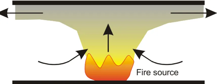
progress and its degree of stratification depend on the airflow in the tunnel. With no air current in the fire zone, the smoke progresses in a symmetrical way on both sides of the fire. The smoke remains stratified until it cools down due to the combined effects of the convective heat exchange with the walls and the mixing between the smoke and the fresh air layer (Figure 1). Other parameters that affect smoke flow and stratification are: the fire heat release rate (see Table 1 for typical fire sizes), tunnel slope, and traffic.
In a tunnel environment, the type of fuel and the resultant fire load can vary enormously due to the different types of materials being transported. Also, multiple fires can occur as the incident escalates. The fire, for example, may be slow burning in nature due to the ignition of a small load of poor combustible material. On the other hand, an explosion can be expected in
the event of ignition of large loads of highly flammable hydrocarbons. The burning rates for most fires in tunnels will not be controlled by the rate of air supply to the fire. Rather, the burning rate and hence the heat release rate will depend on the amount of fuel and its
characteristics. As a rough guide, many arrangements of solid fuel stacks including motor cars and wood cribs forming piles 1-2 m high will burn in the open air at a rate corresponding to a heat release rate in the range of 0.5-1 MW for each square metre of horizontal base area, depending on the fuel height [1]. A large petrol fire in open air will burn at a linear rate of about 4 mm/min, some 2 MW/m2 [1]. In a tunnel, higher burning rates may be possible, because more heat will be fed back from the heated walls and ceiling and from the hot gas layer flowing away from the fire.
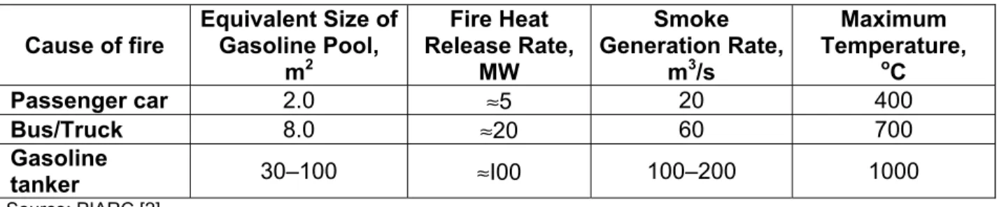
Table 1: Typical Fire Size Data for Road Vehicles
Cause of fire Equivalent Size of Gasoline Pool, m2 Fire Heat Release Rate, MW Smoke Generation Rate, m3/s Maximum Temperature, oC Passenger car 2.0 ≈5 20 400 Bus/Truck 8.0 ≈20 60 700 Gasoline tanker 30–100 ≈I00 100–200 1000 Source: PIARC [2].
Temperature at 10 m downwind of fire with the minimum air velocity necessary to prevent backIayering.
The tunnel slope induces an acceleration of the smoke towards the ascending direction (chimney effect). During the initial stages, the traffic in the tunnel is modified. First, the fire creates an obstacle to the traffic. In the second stage, barriers and/or traffic lights will be operated to stop the traffic upstream of the fire and at tunnel portals. After vehicles present in the tunnel upstream of the fire are stopped, they create an obstacle to the airflow in the tunnel and thus reduce the performance of the ventilation system. These changes in the traffic flow also modify the piston effect induced by the circulation of the vehicles in the tunnel.
Heselden [1] reported that only a small portion of the total heat release contributed to maintain the burning of the fire, in the range of 5-10%. The rest would be available to cause hazard and damage. He also commented that roughly a quarter of the energy from a large flame from solid fuels would be lost through direct radiation, whereas the remainder would further heat the combustion gases and the surrounding air. He concluded that this portion of the energy (convective heat output) was the real problem as it could rapidly move the combustion gases from fire to other locations.
Heselden divided the fire in the tunnel into two regions: flame and combustion gases. Heat fed back from the flame evaporates liquid fuel and causes decomposition of solid fuel into volatile combustibles. These combustibles rise, mix with air and form a flame. The mixing of air takes place by turbulent entrainment. The tip of the flame marks the point where combustion of the flammable volatiles is largely complete, but the combustion products are still very hot and continue to rise in a plume, entraining more air. In the open, this can continue until the gases are cooled so much that the buoyancy vanishes.
In the tunnel, however, the presence of a ceiling alters this picture. Flames from a substantial fire reaching a ceiling can no longer travel upwards and must, therefore, travel horizontally. Since they are hot and therefore lighter than air, they form a hot layer at the
ceiling. For example, a flame in the open that is 7 m high could give flames 10-20 m long when placed in a 5 m high tunnel. This elongation arises because the mixing of air into the flame under the ceiling is much slower than when the flame is travelling vertically, so that in order for enough air to be entrained to burn all the volatile fuel, the horizontal flame has to be much longer. In this case, the turbulent eddies are opposed by buoyancy forces and the rate of air mixing is reduced. In addition, the mixing with the horizontal flame can only occur on one side of the flame. Consequently, a hot smoky flow of combustion products under the ceiling will travel for long distances with limited mixing of air into the layer. This will inhibit dilution of the smoke resulting in high concentrations of smoke and combustion products (for most fuels, the gases should be diluted with approximately 100-1000 times [1] their weight with air before they can be brought to a condition which can be tolerated by human beings). This will seldom be possible in tunnels.
1.1 Tunnel Transport Systems
Tunnels can be classified in different ways. They can be categorized according to their mode of transport, cross-section, length, ventilation, and possible fire hazards. Most tunnels are either roadway or railway tunnels, although some contain both. Tunnel cross sections can be of rectangular, round or arched shape and their length may vary from a few hundred meters to several tens of kilometres. Tunnels can also be categorized in terms of their ventilation system type, as natural, longitudinal, transverse, and semitransverse ventilation systems. There are four main types of tunnel fire hazards: luggage, vehicular, hazardous freight, and the tunnel itself.
2. VENTILATION
SYSTEMS
All tunnels require ventilation to maintain acceptable levels of contaminants produced by vehicle engines during normal traffic operation (normal ventilation), and to remove and control smoke and hot gases during a fire emergency (emergency ventilation). The principle objectives of emergency ventilation are: a) to provide an environment sufficiently clear of smoke and hot gases and at a sufficiently low temperature to permit safe evacuation of motorists; and b) to allow relatively safe access for firefighters [1,2,3].
Establishing air requirements in the roadway tunnel and consequently the capacity of the ventilation system, are challenging due to the difficulty of controlling many variables. Among those variables are the possibility of occurrence of many vehicle combinations and traffic situations during the lifetime of the facility. Methods used to control air contaminant and smoke from fires in a tunnel include longitudinal flow, extraction and dilution.
Ventilation may be provided by natural means, by the traffic-induced piston, or by mechanical equipment. The choice of what ventilation system to use depends on several parameters that include: tunnel length, cross-section and grade; surrounding environment; traffic volume; and construction cost.
2.1 Objectives of Tunnel Ventilation during Fire Emergencies
During a fire emergency, tunnel-operating procedures should be developed to maximize the use of ventilation systems for the removal and control of smoke and hot gases, and to assist in the evacuation and rescue of motorists from the tunnel [3].
In bi-directional traffic road tunnels, the ventilation systems should be operated such that smoke layer would not be disturbed and longitudinal air velocity kept to a minimum. Smoke extraction could be achieved through ceiling openings or through openings located high along tunnel walls (Figure 2).
For unidirectional road tunnels, it is more likely that the motorists will be located
upstream of the fire site. In this case, specific objectives should be met, depending on the type of ventilation system used [3]. For longitudinal systems, “backlayering” of smoke should be prevented by ensuring that longitudinal air velocity is greater than the critical velocity in the direction of the traffic flow (Figure 3). Backlayering is the movement of smoke and hot gases contrary to the direction of the ventilation airflow in the tunnel roadway. It is also recommended in this case that the smoke layer should not be initially disrupted by avoiding activation of the fans near the fire zone. If transverse or reversible semitransverse systems are in use, the NFPA 502 standard [3] requires that the exhaust rate in the fire zone be maximized and that the fresh air supplied in this zone be minimized. Also, it is required, in this case, that a longitudinal airflow in the direction of the traffic be created by operating the upstream ventilation zone(s) in maximum supply and downstream ventilation zone(s) in maximum exhaust.
Criteria, with regard to air temperature and velocity, for the protection of motorists and firefighters during emergency situations vary with age, weight, sex, and acclimatization. Currently, there are not universally accepted tolerance limits or quantitative criteria that directly pertain to air temperature and velocity. As far as the egress routes are concerned, the design objective set by NFPA 502 standard [3] for the emergency ventilation system are as follows:
A stream of noncontaminated air is provided to motorists on a path of egress away from a fire.
During emergencies, evacuees should not be subjected to air temperatures that exceed 60oC.
Longitudinal airflow rates are produced to prevent backlayering of smoke on a path of egress away from a fire. High ventilation rates can cause air velocities great enough to create a hazard to persons walking in such an airstream. Motorists under emergency conditions can tolerate velocities as high as 11 m/s.
Fresh air jets entering the roadway from ceiling openings are unfavourable [1] to smoke stratification, because the jet momentum disrupts the buoyancy effect. A fresh air supply through openings located at the bottom of the sidewall is more favourable to maintaining smoke stratification.
Emergency ventilation systems should be designed based on a design fire size that is related to the types of vehicles that are expected to use the tunnel (Table 1). The fans should be designed to withstand elevated temperatures in the event of a fire (“remain operational for a minimum of 1 hour in an air stream temperature of 250oC”, NFPA 502 [3]).
2.2 Natural Ventilation System
A natural ventilation system depends on the pressure differential that is created by atmospheric conditions (e.g. ambient temperature, or wind between the tunnels’ two portals) and differences in elevation to maintain airflow and a satisfactory environment in the tunnel. An additional airflow is created by the piston effect of moving traffic. However, continuous changes in meteorological and operating conditions make such systems unreliable for maintaining an acceptable environment in the tunnel all the time. A change in wind direction or speed can negate all the natural effects, including the piston effect. The pressure must be large enough to overcome tunnel resistance, which is influenced by tunnel length, cross-sectional geometry, wall roughness, number of vehicles in the tunnel, and air density. For a tunnel with anticipated heavy or congested traffic flows, the adequacy of a natural ventilation system should be thoroughly evaluated and the installation of a mechanical system with fans should be considered for normal operations. Designs for natural ventilation systems are discussed in reference [2].
Smoke from a fire in a tunnel with only natural ventilation moves up the grade driven primarily by the buoyant effect of hot smoke and gases. The steeper the grade the faster the smoke will move, thus restricting the ability of motorists trapped between the incident and the portal at the higher elevation to evacuate the tunnel safely.
Massachusetts Highway Department/ Federal Highway Administration (MHD/FHWA) [4] demonstrated how smoke moved in a naturally-ventilated tunnel with a 3.2% grade for two heat releases, 20 and 50 MW. For the 20 MW fire test, the smoke layer started to descend after 3 min and filled the road tunnel after 5 min with a peak speed of 6.1 m/s. For the bigger fire of 50 MW, it took the smoke layer 2 min from the start of the descent at 1 min to fill the roadway with a peak speed of 8.1 m/s. Generally, emergency mechanical ventilation should be used to extract smoke and hot gases generated during a fire for naturally-ventilated urban tunnels over 244 m in length [2]. Other countries have proposed different guidelines to limit the application of natural ventilation in road tunnels [5].
Natural and traffic-induced ventilation is adequate for relatively short tunnels and tunnels with low traffic volume (or density). Long and heavily traveled tunnels should have mechanical ventilation.
2.3 Mechanical Ventilation System
Two types of mechanical ventilation systems are used for road tunnels: normal and emergency systems. Normal ventilation is used during normal traffic operations to maintain acceptable levels of contaminants in the tunnel. Emergency ventilation is used during a fire emergency to remove and control smoke and hot gases. The primary objective of emergency ventilation is to provide an environment sufficiently clear of smoke and hot gases and at a sufficiently low temperature to permit safe evacuation of motorists, and to allow safe access for firefighters.
There are different mechanical ventilation layouts used in road tunnels: longitudinal semi-transverse and full transverse systems.
2.3.1 Longitudinal ventilation
The longitudinal ventilation system (Figure 4) creates a longitudinal flow along the roadway tunnel by introducing or removing air from the tunnel at a limited number of points. The ventilation is provided either by injection (Figure 4a), by jet fans (Figure 4d), or by a combination of injection or extraction at intermediate points in the tunnel (Figure 4b and 4c). The longitudinal form of ventilation is the most effective method of smoke control in a highway tunnel with unidirectional traffic. In the event of a fire in a unidirectional tunnel, it is usually assumed that the traffic ahead of the fire will proceed to the exit portal and the traffic behind the fire will come to a stop. The ventilation system would be operated to force the smoke and hot gases in the direction of the empty tunnel to provide a clear and safe environment behind the fire for evacuees and fire fighters.
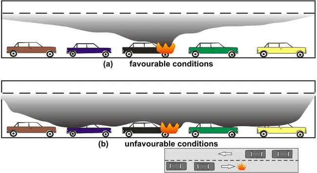
If the ventilation capacity is sufficient (Figure 5b and 5c), all of the heated air and smoke will flow in the downstream direction. If the ventilation is weak (Figure 5a), the upper layer of heated air and smoke may flow in the opposite direction causing backlayering. The occurrence of backlayering depends on many factors including the intensity of fire, the grade and geometry of the tunnel, and the velocity of the ventilating air approaching the fire. The ability of the longitudinal ventilation system to prevent backlayering is the current industry standard to measure the adequacy of the system for smoke control.
As the length of the tunnel increases, excessive air velocities could be expected in one or a few locations across the roadway. Moreover, in the event of a fire, smoke would be drawn throughout the entire length of the roadway. By introducing a uniform air distribution
(semitransverse ventilation system), these problems can be mitigated.
An injection longitudinal ventilation system, in which the fresh air is supplied or the smoke is extracted at a limited number of locations in the tunnel, is economical as it uses the least number of fans, and does not require extra ducts for the distribution of air. The
longitudinal ventilation can be achieved by extracting contaminates or smoke with a fan shaft. This system creates a positive stack effect with fresh air being drawn through the portals. A ventilation system could also be designed with two shafts near the centre of the tunnel: one for exhaust and one for supply. This arrangement has the advantage of reducing contaminant or smoke concentrations in one half of the tunnel. The disadvantage of this system is that adverse
wind conditions may reduce the airflow, causing the contaminant concentration to rise in half of the tunnel, and the flow could be short-circuited from the fan to the exhaust.
Longitudinal ventilation can be provided using specially-designed axial jet fans mounted on the tunnel ceiling. This type of system does not require a large space to house ventilation fans in a separate structure or ventilation building. However, it may require a tunnel of greater height or width to accommodate the jet fans so that they are out of the tunnel's dynamic clearance envelope. Moreover, a fire can significantly increase air temperature in the tunnel roadway or duct and the fans could be exposed to the high gas and smoke temperature. The temperatures shown in Table 2 provide guidance in selecting the design temperature for fan equipment.
Table 2 [2]: Maximum Temperature Experienced at Ventilation Fans (Memorial Tunnel Fire Ventilation Test Program)
Nominal FHRR MW
Temperature at Central fansa
oC
Temperature at Jet fansb
oC
100 163 677
50 124 371
20 107 232
a
Central fans were located about 213 m from fire site.
b
Jet fans were located 52 m downstream of fire site.
The ventilation system must generate sufficient longitudinal air velocity to prevent backlayering of smoke. The air velocity necessary to prevent backlayering of smoke over the stalled motor vehicles is the minimum velocity needed for smoke control in a longitudinal ventilation system and is known as the critical velocity. The critical velocity depends on the fire heat release rate (fire size), the slope, and the tunnel section geometry. The critical velocity, minimum steady-state velocity, is used to define the fan requirements for smoke control from possible fires and can be determined using a simple equation [7]:
3 1 c P P 2 1 c T AV C Q A C gHQ K K V + = ∞ ∞ ∞
ρ
ρ
(1)where Vc is the critical velocity, K1 and K2 are constants, g is the acceleration due to gravity, H is the tunnel height, Q is the fire heat release rate, A is the tunnel cross-sectional area, Cp the specific heat of air, ρ∞ and T∞ are the density and temperature of ambient air.
If the longitudinal air velocity is greater than the critical velocity, the smoke downstream of the fire will not stratify (Figure 5c). In cases where the air velocity is lower than or equal to
the critical velocity, the smoke would progress upstream of the fire and would remain stratified (Figure 5a and 5b).
Permanent International Association of Road Congresses (PIARC) identified two phases
in the event of fire in a tunnel [5, 6]:
Evacuation phase: during which, the natural stratification of hot smoke should be maintained by ensuring zero longitudinal velocity in the fire zone (Figure 1).
Fire control phase: during which, the smoke will be pushed back on a side of the fire to ensure safe operation near the fire. In this phase, the longitudinal velocity
upstream of the fire must be higher than the critical velocity (Figure 5c).
2.3.2 Semitransverse ventilation
A semitransverse ventilation system can be either a supply or an exhaust system (Figure 6b and 6c). This type of ventilation system induces the distribution of (supply system Figure 6b) or collection of (exhaust system Figure 6c) air uniformly throughout the length of a road tunnel in a duct fitted with supply outlets spaced at predetermined distances. Semitransverse ventilation is normally used in tunnels up to about 2134 m. Beyond that length, the tunnel air speed near the portals becomes excessive. This type of ventilation has the advantage of being less affected by atmospheric conditions since the tunnel airflow is fan-generated.
For semitransverse ventilation, fresh air is best introduced at the vehicle exhaust pipe level to dilute the exhaust gases immediately (Figure 6b). An adequate pressure differential between the duct and the roadway must be generated and maintained to counteract the piston effect induced by the traffic flow and adverse atmospheric winds.
If a fire occurs in the tunnel, the supply air initially dilutes the smoke. Subsequently, it should be operated in reverse mode so that fresh air enters the tunnel through the portals (Figure 6c) to create a respirable environment for fire fighting efforts and emergency egress. Therefore, the ventilation configuration for this type of system should preferably have a ceiling exhaust and reversible fans so that smoke can be drawn up to the ceiling in an emergency.
A combination supply and exhaust system should be [2] applied only in a unidirectional tunnel where air entering with the traffic stream is exhausted in the first half of the tunnel, and air supplied in the second half of the tunnel is exhausted through the exit portal (Figure 7d). In a fire emergency, the combined ventilation system would create a longitudinal air velocity in the tunnel roadway, which extracts smoke and hot gases at uniform intervals.
2.3.3 Full transverse ventilation
Full transverse ventilation (Figure 6a) is used in extremely long tunnels and in tunnels with heavy traffic volume. This ventilation system comprises both a supply and an exhaust duct to achieve uniform distribution of supply air and uniform collection of vitiated air throughout the tunnel length. This configuration produces a uniform pressure along the roadway with no longitudinal airflow being generated except that created by the traffic piston effect. An adequate pressure differential between the ducts and the roadway should be maintained to ensure proper air distribution under all ventilation conditions. In the event of a fire, the exhaust fan should attain its maximum available capacity while the supply should be maintained at a relatively low capacity. This scheme ensures that the stratified smoke at the ceiling remains at that higher elevation and is extracted by the exhaust ducts without mixing with the lower fresh air. In this
way, a respirable environment would be maintained at the roadway for fire-fighting and emergency egress and fresh air would be allowed to enter through the portals.
Ventilation scenarios [2] should be configured such that the section with traffic trapped behind a fire is provided with maximum supply and no exhaust, while the section on the other side of the fire where traffic has been driven away is provided with maximum exhaust and minimum or no supply. Fieldner [8] conducted full-scale tests and reported that for a rapid dilution of exhaust gases, supply air inlets should be located at the exhaust pipe level, and exhaust outlets should be placed in the ceiling.
2.3.4 Other Ventilation Systems
The ventilation systems described earlier could be combined into a hybrid system to address a specific problem in a tunnel. A few modifications can be made to improve the
performance of these systems. Among these are: single point extraction and oversized exhaust ports.
A single point extraction (Figure 7e) could be added to a transverse system with large openings to the exhaust duct. These openings include devices that can be operated during a fire emergency to extract a large volume of smoke as close to the fire source as possible. Tests conducted as a part of the Memorial Tunnel Fire Ventilation Test Program [4] concluded that this concept is effective in reducing the temperature and smoke in the tunnel. The size of openings tested ranged from 9.3 to 27.9 m2.
Oversized exhaust ports (Figure 7f) are simply an expansion of the standard exhaust port installed in the exhaust duct of a transverse or semitransverse ventilation system. Two methods can be used to create such a configuration. One is to install on each port expansion a damper with a fusible link; the other uses a material that when heated to a specific temperature, melts and opens the airway. Several tests of such meltable material were conducted as part of the Memorial Tunnel Fire Ventilation Test Program but with limited success [4].
In addition, other modifications could be implemented for the transverse ventilation system to allow for single-zone or two-zone ventilation. In the two-zone configuration, as opposed to the single-zone ventilation, the tunnel is divided into two ventilation zones such that one half of the tunnel acts as a supply zone and the other half as an exhaust zone (Figure 7d).
3. EXPERIMENTAL
PROCEDURES
Successful numerical simulations of fires in large complicated structures, such as
tunnels, are largely dependent on the accuracy of the input data. The input data includes: initial conditions of the tunnel environment, prevailing winds, ventilation flows, and most importantly, the heat release rate from the burning objects. Research throughout the world has tried to effectively measure these input parameters, especially heat release rates of different burning materials.
Aerodynamic tests can be carried out on site to identify the capacities of the ventilation system before conducting fire tests. These tests include the verification of the available airflows in the ventilation ducts, as well as the capabilities of the ventilation system to control the
longitudinal air velocity in different locations in the tunnel, under various meteorological situations. In a later stage, fire tests can be carried out on site to check the adequacy of the ventilation to meet the safety objectives. These checks relate to the following points:
Physical conditions actually noted at the time of a fire.
Limits of the ventilation procedures (sensitivity of the procedure in terms of stability of the physical situation and smoke stratification).
Operating instructions must try to take into account as many situations as possible. More test configurations (fire location, initial air velocity in the tunnel and fire heat release rate) increases knowledge on the interaction of the ventilation system with a fire in the tunnel, and makes it possible to define more precisely the operating instructions. If only a few
configurations can be tested, it is advisable to choose those that are a priority and most unfavourable with regards to user safety.
3.1 PIARC FIRE TEST RECOMMENDATIONS
PIARC [5, 6] provides some empirical recommendations for fire tests during the self-evacuation phase.
3.1.1 Tunnel operating condition
To carry out fire tests, it is advisable to have at one’s disposal the tunnel and its full capacity of ventilation. For this reason, the fire tests are delicate operations because they must be carried out before the opening of the tunnel or during its operation, with tight time schedules. It is thus necessary that these tests be led correctly to minimize disruptions and maximize safety.
Procedures to protect people must be established before the test. Protection also relates to both the equipment that can be isolated and the structure of the tunnel, which should not be exposed to excessive temperatures. In other words, security management must be considered in the design of the tests. The fire heat release rate is inevitably limited and the scenarios must take into account the protection requirements. In the case of a fire test during operation in a tube where traffic is maintained in the other tube, it is necessary to ensure that smoke is not recycled in the tube open to traffic.
3.1.2 Fire simulation
Different sources of smoke can be used to represent fires in tunnels [1]; cold smoke, pool fires, and real fires. The following is a description of each type along with their merits.
3.1.2.1 Cold smoke tests
The use of smoke-producing products only is not representative of a fire. The
production of heat by the fire is not taken into account. This limits the representation of the fire phenomena:
Critical velocity, which depends on the heat release rate, is underestimated.
The stability of the natural smoke stratification, which depends on the temperature, and therefore, the heat release rate, is underestimated.
This approach is not recommended to establish operating instructions because the phenomena related to the presence of a real fire are not reproduced.
3.1.2.2 Pool fires and hot smoke tests
This generally involves hydrocarbon pool fires (heptane or fuel oil). These fires are well known and they are the subjects of a significant bibliography [9, 10]. The advantage of these fires is their stability: their heat release is constant as a function of time. Their change under the effect of longitudinal ventilation is well known [10].
The use of this type of fire leads to well-characterized situations that emphasise the effect of ventilation on smoke behaviour. The use of a hydrocarbon fire makes it possible to guarantee an optimal smoke stratification taking into account the aerodynamic conditions present in the tunnel. The capacity of the ventilation system to maintain a situation initially favourable for evacuation can thus be evaluated. These situations make it possible to support the choice of a ventilation procedure according to the safety objectives.
It is preferable to establish the operating instructions using tests carried out with
hydrocarbon fires rather than with car fires, because they lead to the most favourable conditions regarding initial smoke stratification.
3.1.2.3 Real fires tests
Realistic fires are generally use wrecks of road vehicles. The heat release rate
developed by this type of fire is well known. Second order variations such as, turbulence or the chaotic emissions of puffs of smoke, result in a smoke behaviour that is much more difficult to characterize and introduce substantial differences compared to calibrated fires tests. For example, during the fire tests carried out in the Puymorens tunnel [11], the fire with a passenger car which completed a set of ten heptane pool fires, was characterized by losses of stratification which had not been observed for calibrated fires of the same heat release rate. The
comparison of the temperature fields, for identical situations of ventilation actually did not reveal notable differences. It should be noted that new vehicles might produce quite different heat release rates as a result of the new materials with different combustible masses.
3.1.2.4 Power and duration of the fire
The majority of the fire tests have been carried out with heat release rates lower than 5 MW. This value seems to be reasonable in comparison with the risk of damage of the tunnel vault close to the fire. If tests with higher heat release rates are necessary, it is recommended that they be preceded by preliminary tests with lower heat release rate (ex: Tunnel de la Grand Mare [6]).
With hydrocarbon fires, it is generally possible (according to cases where a tunnel was used) to reach several steady state situations during the same fire test, and thus to test various aerodynamic configurations. The use of pools with a constant fuel level makes it possible to carry out tests over a greater duration than with simple pools.
3.1.3 Measurements
Measurements have two objectives:
Monitoring the temperatures during each test. This information can be used to manage safety during the test.
Monitoring smoke stratification, visibility, and backlayering.
The first objective requires the installation of thermocouples on exposed places in the fire zone (equipment and structure of the tunnel). The second objective requires a methodical approach in which it is necessary, before the tests, to identify the phenomena to be
characterized. At the end of this analysis, it is necessary to determine the nature, location and number of sensors to be installed in the tunnel.
3.2 The Memorial Tunnel Fire Ventilation Test Program (MTFVTP)
The MTFVTP [12] was created in the late 1980s in recognition of absence of a definitive and generally accepted consensus regarding the proper design and operation of road tunnel ventilation systems in a fire emergency. Further, as a result of significant decreases in vehicle engine emissions over the past three decades, ASHRAE [2] indicated that the practice used an exhaust rate of at least 100 cubic feet per minute per lane foot (100 cfm/lf). The 100 cfm/lf recommended ventilation requirement for normal operations may not provide adequate ventilation capacity for a fire emergency. The need for such a program was identified by members of the ASHRAE Technical Committee 5.9, Enclosed Vehicular Facilities (TC 5.9), which formulated the goals and scope of work (Phase I Report issued in March 1989). The first three phases of the program addressed test program development, test facility design and construction, testing and data evaluation. Phase IV of the program focused on the development and validation of a customized CFD code specifically for tunnel applications. Data from the full-scale fire tests was used as the basis for validation. With a validated code, the results of the tests could be effectively applied to any tunnel. The work of all phases was performed under a joint venture agreement between Bechtel/Parsons Brinckerhoff (B/PB) and MHD for work on the Central Artery/Tunnel project in Boston.
The basic objectives of the program were to develop data which would provide a definitive evaluation of the life safety capabilities of various configurations of transverse ventilation systems in a fire situation, and to assess the current recommended ASHRAE ventilation fire safety guideline of 100 cfm/lf exhaust airflow rate. In addition, the Test Program was designed to evaluate longitudinal ventilation systems using jet fans.
The MTFVTP consisted of a series of full-scale fire tests conducted in an abandoned road tunnel, namely, the Memorial Tunnel. The two-lane tunnel through a mountain is located near Charleston, West Virginia and has a length of 854 m and a 3.2 percent grade. Various tunnel ventilation systems and configurations were operated to evaluate their respective smoke and temperature management capabilities. A total of 98 full-scale tests were carried out. These tests generated a significant database for the design and operation of road tunnel ventilation systems under fire emergency conditions.
3.2.1 MTFVTP tested ventilation configurations
In preparation for the MTFVTP, the tunnel was modified and instrumented to allow operation and evaluation with different ventilation system configurations. The test
configurations included:
Full transverse ventilation (Figure 7a): In this case, the duct above the roadway was
divided to allow for separate supply and exhaust air ducts. Fresh air, supplied by the south fans, was introduced at the roadway. Smoke and hot gases were exhausted through exhaust ports in the ceiling and discharged out the north ventilation stacks.
Partial transverse ventilation (Figure 7b and Figure 7c): For this type of ventilation, the
south and north fans weer operated in either exhaust mode (Figure 7b) with fresh air drawn into the tunnel through the two portals, or supply mode (Figure 7c) with fresh air supplied by the north and south fans through the ceiling ports. As the air entered the tunnel, it mixed with the smoke and hot gases and was extracted through the ceiling exhaust ports (Figure 7b) and discharged out through the north and south ventilation stacks or exited the tunnel through the two portals (Figure 7c).
Two-zone partial transverse ventilation (Figure 7d): Partial transverse ventilation
systems were installed in single-zone (Figure 7b and Figure 7c) or two-zone configurations (Figure 7d). In this configuration, the mid-tunnel duct bulkhead was in place dividing the tunnel into ventilation zones. The supply zone ceiling ports were balanced to provide uniform supply over the length of this zone. Likewise, a uniform exhaust over the exhaust zone length was maintained.
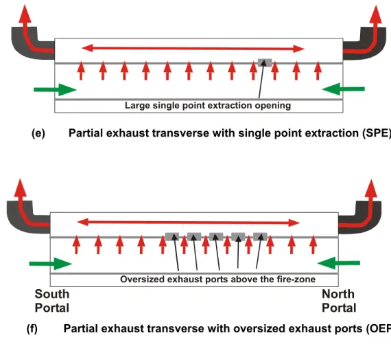
Partial transverse ventilation with single point extraction (SPE) (Figure 7e): Single
point extraction openings were used for the removal of large quantities of smoke and hot gases close to the fire in order to prevent extensive migration of smoke. These openings ranged from 9 to 28 m2 in size and were spaced at 30 m centres along the tunnel. The south and north fans were operated in the exhaust mode, with air drawn through the two portals. After mixing with the smoke and hot gases from the fire, the air was extracted through standard ceiling exhaust ports and a large single point extraction opening located near the fire.
Partial transverse ventilation with oversized exhaust ports (OEP) (Figure 7f):
Oversized exhaust ports were used to improve the performance of a partial transverse exhaust ventilation system. The OEP represented a modification to transverse type system, which provided smoke extraction capability in the immediate location of a fire. This
approach consisted of 2.8 m2 oversized exhaust ports spaced approximately 9 m apart (comparable to normal-sized exhaust port spacing) and designed to fully open when subjected to the heat of a fire. The south and north fans were operated in the exhaust mode. This caused fresh air to enter the tunnel through the two portals and mix with the smoke and hot gases from the fire. The mixed air was extracted through standard ceiling exhaust ports and oversized exhaust ports located above the fuel pans.
Natural ventilation: In this case, smoke and heat movement were determined by tunnel
grade, buoyancy, and meteorological conditions. Two natural ventilation tests were performed with the tunnel ceiling removed. The data extracted from these tests provided information about the length, depth, and stability of the stratified smoke layer produced by 20 and 50 MW fires.
Longitudinal ventilation with jet fans: Jet fans were installed in the crown of the tunnel in
groups of three. The jet fans discharged high velocity air that forced a mass of air
longitudinally through the tunnel in a north-to-south direction. The longitudinal air velocity generated by the jet fans was a function of the thrust and the number of operating fans, and independent of which fans were operating. The smoke and hot gases were pushed out of the south portal.
In addition to the type of ventilation system, the fire test parameters included fire heat release (rates of 10, 20, 50 and 100 MW), ventilation rates, ventilation system response times (0, 2 and 5 minutes), and different portal openings. Tests were also conducted to assess the impact of longitudinal air velocities on the effectiveness of a foam suppression system.
The tunnel was equipped with instrumentation and recording equipment for data acquisition. Sensors measuring air velocity, temperature, carbon monoxide (CO), and carbon dioxide (CO2) were installed at various tunnel sections. Data from these sensors were
recorded. Smoke generation and movement and the resulting effect on visibility were assessed using seven remote-controlled television cameras with associated recording equipment.
3.2.2 MTFVTP basic findings
In the MTFVTP, various smoke management strategies and combinations of strategies were employed, including extraction, transport, control direction of movement, and dilution to achieve the goals of offsetting buoyancy of the smoke and external atmospheric conditions and to prevent backlayering. A total of 98 tests were conducted. The basic findings to date are summarized in the following sections.
3.2.2.1 The ASHRAE criteria
The ASHRAE criterion of 100 cfm/lf of tunnel for normal road tunnel ventilation operations has been used as a minimum design basis for many years. However, prior to the MTFVTP project, there had been no validation of that value. It was noted from the fire tests that while this criterion might be appropriate for some situations, it was not applicable in others, and was therefore limited as a general criterion. The Memorial Tunnel fire ventilation tests showed that longitudinal airflow near a fire is equally important as the extraction rate for temperature and smoke management. Therefore, specifying a ventilation rate for temperature and smoke
management, solely on its extraction capabilities, was found to be insufficient. Further, any criterion established for emergency ventilation should include the impact of the tunnel’s physical characteristics and the tunnel’s ventilation system.
3.2.2.2 Longitudinal ventilation systems with jet fans
Longitudinal ventilation using jet fans was effective in managing the direction of the spread of smoke and heat resulting from heat releases up to 100 MW in a 3.2 percent grade tunnel. The required longitudinal air velocity to prevent backlayering in the
Memorial Tunnel was approximately 3.0 m/s for a 100 MW fire. The longitudinal velocity generated by jet fans managed temperature and smoke only on one side of the fire. The smoke and temperature conditions on the opposite side, at times, were higher.
Therefore, such systems should be applied only in road tunnels with a unidirectional traffic flow.
⇒
⇒ Test data indicated that air velocities of 2.5 to 3.0 m/s were sufficient to preclude the backlayering of smoke in the Memorial Tunnel over the range of fire sizes tested (10 MW
to 100 MW). Comparison of the measured air velocity to prevent backlayering with the theoretical critical velocity indicated that the theory appeared to over-predict the
minimum air velocity requirements for fire sizes in the 50 to 100 MW range, by approximately 5 to 15%.
It was concluded that the design of longitudinal ventilation systems should take into account the throttling effect of airflow (rapid expansion of air past the fire site causing pressure losses which reduce the tunnel airflow). During the tests of longitudinal
ventilation, the thermal effects of a fire significantly reduced tunnel airflows, on the order of 10% for a 10 MW fire, and 50% to 60% for a 100 MW fire.
⇒
⇒
⇒
⇒
⇒
Jet fans positioned downstream of, and close to the fire were subjected to temperatures high enough to cause their failure. Jet fans positioned 52 m downstream of the fire were subjected to the following temperatures: 204°C for a 20 MW fire, 332°C for a 50 MW fire, and 677°C for a 100 MW fire. As a result of the 100 MW fire, 1 of the 3 jet fans failed. Accordingly, it was recommended that this condition should be considered in the system design and selection of emergency operation modes.
3.2.2.3 Transverse ventilation systems
In general, the effectiveness of transverse ventilation systems for smoke and heat management was significantly improved by dividing the tunnel into multiple zones. This provided the capability to select the direction of longitudinal airflow and produced heat and smoke movement in a preferred direction. The two-zone ventilation system tested in the MTFVTP controlled the direction and magnitude of longitudinal airflow. Airflow rates of 100 cfm/lf contained high temperatures from a 20 MW fire within 100 feet of the fire in the lower elevations, and smoke within 200 feet.
Full transverse ventilation
Full transverse ventilation systems could be installed in single-zone or multi-zone
configurations and could be operated in a balanced or unbalanced mode. A single-zone, balanced (equal flow rates for supply and exhaust air) full transverse systems indicated very limited smoke and temperature management capability. Ventilation rates of 100 cfm/lf exhaust capacity did not manage conditions resulting from heat release rates of 20 MW and greater. Single-zone full transverse systems operated in the unbalanced mode had improved temperature management capability. However, even 100 cfm/lf exhaust capacity provided only limited temperature and smoke management for a 20 MW heat release rate. Multiple-zone full transverse systems showed improved capability to manage smoke and temperature by creating longitudinal airflow.
Single-zone balanced full transverse ventilation operated at 100 cfm/lf was ineffective in smoke and heat management for fire sizes of 20 MW and higher. Balanced ventilation allowed no control of the longitudinal air velocity in the tunnel, and hence, very limited smoke management was possible. In this case, smoke and heat movement was determined by tunnel grade, buoyancy, and meteorological conditions. Single-zone unbalanced full transverse ventilation generated some longitudinal airflow in the tunnel, which offset some of the effects of buoyancy for a 20 MW fire. This condition resulted in slightly-improved temperature management capability as compared to a balanced system. However, the effectiveness of unbalanced full transverse ventilation was sensitive to the location of the fire in a tunnel, since there was no control over the direction of longitudinal airflow.
Partial transverse ventilation
The standard practice in the industry has been to design ventilation systems for fire emergencies based on fan capacities expressed in cfm/lf. However, the fire ventilation tests indicated that the longitudinal airflow was a major factor in the management and control of smoke and heat generated in a fire situation. As demonstrated by tests with the partial transverse supply configurations, dilution as a sole means of temperature and smoke management was found to be ineffective. Some means of extraction was
necessary. For bi-directional traffic flow, it was necessary to remove smoke and heat at or near the fire. Therefore, both extraction and longitudinal airflow were crucial
parameters. Extraction and longitudinal airflows, when effectively coupled, significantly increased the capabilities of a ventilation system and limited the spread of smoke and heat during a fire. Multiple-zone ventilation systems allowed control over the direction and magnitude of longitudinal airflow, and could effectively manage smoke and temperatures in the tunnel. Two-zone partial transverse ventilation with 100 cfm/lf effectively managed the smoke for fires with 20 MW heat release rates.
⇒
⇒
⇒
⇒
⇒
Single-zone partial transverse systems capable of only supplying air (no possible reversal of fans to exhaust air) were relatively ineffective in smoke or temperature management. Single-zone partial transverse systems which could be operated in the exhaust mode, provided a degree of smoke and temperature management by
generating a longitudinal airflow in the tunnel. However, they did not allow for control of the airflow direction. Thus, partial transverse exhaust ventilation was also found to be highly sensitive to the location of the fire in the tunnel.
Partial transverse ventilation with SPE and OEP
The ability to extract smoke quickly and as close as possible to the fire was found to significantly reduce smoke and heat migration in undesired directions, and facilitate two-way traffic operations. This localized extraction was possible with the application of SPE and OEP to transverse ventilation systems. SPE systems were found to be effective in two-way traffic flow with a dependency on the location, size and spacing of the SPE openings. An SPE located upgrade of the fire was very effective in temperature and smoke management. With the SPE located downgrade of the fire, only minimal improvement in temperature and smoke conditions over a basic single-zone partial transverse exhaust system was achieved. A single point opening of 28 m2 was most effective in temperature and smoke management of the SPE sizes tested. Significantly greater smoke and heat spread was observed with the 9.3 m2 opening, compared to the 28 m2 opening.
In the one test in which two single point openings north of the fire were utilized, a stagnation zone was formed resulting in smoke accumulation between the openings. For 20 MW fires, partial transverse exhaust ventilation operated with 100 cfm/lf and supplemented with a large (28 m2) single point opening limited smoke and heat
migration to within approximately 61 m of the fire. A partial transverse exhaust system supplemented with oversized exhaust ports and operated with 85 cfm/lf limited high temperatures to 30.5 m from the fire, and sustained the smoke layer above the occupied zone. For 50 MW fires, partial transverse exhaust ventilation operated with 110 cfm/lf and supplemented with a large (28 m2) single point opening limited smoke and heat migration to 85 m from the fire.
The SPE transverse type system effectively managed smoke and temperature
applicable to bi-directional traffic flow, with a degree of dependency, however, on the location and spacing of the SPE openings. Smoke and heat drawn from the fire to the SPE opening could pass over or possibly go around stalled traffic and vehicle
occupants.
The OEP provided significant improvement in temperature and smoke conditions relative to the basic transverse ventilation system using conventional size exhaust ports. The OEP enhancement was also applicable to tunnels with bi-directional traffic.
⇒ ⇒ ⇒ ⇒ ⇒ ⇒ ⇒ ⇒ ⇒ ⇒ 3.2.2.4 Natural ventilation
Natural ventilation resulted in an extensive spread of heat and smoke upgrade of the fire. However, the effects of natural buoyancy are dependent on the fire size and the physical characteristics of the tunnel.
3.2.2.5 General conclusions
Fan response time, which is the interval between the onset of a fire and the ventilation system activation, should be minimized since hot smoke layers can spread quickly, e.g., up to 488 to 579 m in the initial two minutes of a fire.
The maximum temperature experienced at the inlet to the central fans (closest location to the fire - approximately 213 m) was 163°C for a 100 MW fire, 124°C for a 50 MW fire, and 107°C for a 20 MW fire.
A visibility criterion was defined as a critical limit below which a safe evacuation of people would become difficult due smoke obscuration. Another temperature criterion was defined as critical conditions for evacuating people and rescue service personnel, respectively. The limiting conditions of the visibility criterion were attained more quickly than were those of the temperature criterion. Carbon monoxide (CO) levels near the roadway never exceeded the guidelines established for the test program.
The effectiveness of the foam suppression system was not diminished by the operation in a strong longitudinal airflow. In the MTFVTP, the system was operated and tested in conditions with 4.1 m/s longitudinal air velocity.
Adequate quantities of oxygen to support combustion were available from the tunnel air. The possible increase in fire intensity resulting from the initiation of ventilation did not outweigh the benefits.
A significant difference was observed in smoke spread with the ceiling removed (arched roof) and the ceiling in place. The smoke and hot gas layer, migrating along the arched roof, did not descend into the occupied zone as quickly as in the tests with the ceiling in place. Therefore, the time for the smoke layer to descend to a point where it poses an immediate life-safety threat was dependent upon the fire size and tunnel geometry, specifically the tunnel height. In the Memorial Tunnel, smoke traveled between 290 and 366 m along the arched roof before cooling and descending into the occupied zone. The effectiveness of the tunnel lighting system having fixtures mounted near the ceiling was quickly degraded, decreasing visibility and seriously compromising evacuation capability.
In a road tunnel, smoke management was found to require either direct extraction at the fire location or the generation of a longitudinal velocity in the tunnel capable of
transporting the smoke and heat in the desired direction to a point of extraction or discharge from the tunnel. Without a smoke management system, the direction and rate
of movement (natural ventilation), would be determined by the tunnel grade (if any), fire conditions and external meteorological conditions.
The authors indicated that the data could be directly applicable to other tunnels having similar dimensions to the Memorial Tunnel. However, they commented that with further investigation, the effects of tunnel grade, tunnel physical characteristics, and other parameters on the capabilities of ventilation systems could be determined, and the data expanded for applicability to tunnels having dimensions different from the Memorial Tunnel. The
determination of these effects and expansion of the data was possible using computational fluid dynamics (CFD). This information further enhanced the value of the Test Program and the usefulness of its data.
3.3 Hot Smoke Tests in Australian Tunnels
The Commonwealth Scientific & Industrial Research Organization (CSIRO) and the South Australian Metropolitan Fire Services (SAMFS) [13] developed hot-smoke tests in the early 1990s. Smoke tests were conducted to verify smoke modelling predictions for both natural and mechanically-ventilated parts of buildings, particularly atria. In addition, a large amount of scientific data was gathered using instrumentation installed prior to the hot-smoke tests. These smoke tests identified a surprising number of defects in the systems being tested. In
1991/1992, a series of experiments (Deeds Road tests [14]) was devised and carried out by SAMFS and Adelaide University with assistance from CSIRO. As a result of these research efforts, an Australian Standard was developed for hot-smoke tests (current edition is AS 4391, 1999). The usefulness of hot smoke tests has been recently re-examined in the Fire Engineers
Journal [15].
Although initially intended to verify modelling predictions for smoke movement, the current application of hot smoke tests proved to be valuable as a commissioning tool. As mentioned above, a number of operational defects were identified in the hot-smoke tests that were not identified in the normal commissioning process. In particular, the communication or lack of communication between systems such as smoke detection systems, fire control panels, smoke exhaust fans, smoke dampers and emergency warning systems proved to be of great importance in hot-smoke tests. In addition, situations were identified where smoke exhaust grills were covered by plasterboard sheets, obstructions were left in ducts, fans and dampers were wired incorrectly, etc.
The effectiveness of make-up air provisions, the performance of pressurization systems and the performance of smoke baffles separating smoke control zones can be examined in hot-smoke tests. To assess the performance characteristics of these parameters, the test should be specifically designed to represent calculations used in the design of the smoke management system or calculations required to reproduce the smoke behaviour prior to the test. In natural ventilation designs, hot-smoke tests demonstrated, on a number of occasions, the adverse effects of external wind, requiring subsequent adjustments to control the opening of vents. In general, hot-smoke tests have two purposes:
1. To test smoke management systems.
3.3.1 Case Studies of Hot–Smoke Tests in Tunnels 3.3.1.1 Homebush Bay railway tunnel
The purpose of the hot-smoke test was to assess the performance of the smoke
management systems. In particular, the ability of the systems to limit backlayering of hot smoke at roof level in the tunnel was assessed. Visibility downstream from the fire was also assessed.
The test location was based on the fire location used for modelling predictions and was adjusted so as to be clear of insulators and cables at roof level within the tunnel. The test fire was placed on a flat-bed rail vehicle and a passenger train was parked on the downwind side of the test fire. A diesel locomotive, which had moved the flat-bed truck into position, was parked approximately 10 m upwind from the fire trays.
The specification called for smoke production similar to that produced by a 20 MW fire, but for safety reasons and to minimise the heat impact on the tunnel structure and the train, the fire size was smaller than 20 MW. The number of trays and their sizes were arranged so as to provide a smoke volume equivalent to that produced by a 9.5 MW fire. To achieve this smoke production rate, there were eight trays. The trays were separated from each other by
approximately 2 m in order to create separate fire plumes to produce the necessary smoke volume and to reduce temperatures at the roof of the tunnel. Tray sizes and test procedures were in accordance with the Australian Standard for hot-smoke testing (AS/NZS 4391 (Int): 1996).
The NSW Fire Brigades were in attendance and were in charge of safety. CSIRO provided portable fire extinguishers, and CSIRO personnel required to work within the smoke wore breathing apparatus. The main observations made during these tests included:
• No backlayering was evident at the tunnel roof upwind from the test fires. • Downwind from the fires visibility was estimated to be 10 m.
• Smoke velocity at floor level 40 m from the test fires (in the wide part of the tunnel) was not more than 5 m/s.
3.3.1.2 Museum Station underground platform tunnel, Sydney
Museum Station has two platforms, one on either side of the twin tracks. The platforms are approximately 160 m long and there is a concrete arched roof over the platforms and tracks. At each end of the platform, the tracks enter an arched roof single tunnel. The roof over the platforms is approximately 6 m above the platform level, and the train tunnels are approximately 3 m above the platform level. A system of pedestrian tunnels connects the platforms with the concourses above.
The purpose of the tests was to demonstrate that a fan-induced flow of air from the concourses through the pedestrian tunnels was sufficient to keep the pedestrian tunnels smoke-free even with trains running through the station at low speed (about 15 km/h). The State Rail Authority exposed emergency services personnel, train drivers, ambulance staff and the railway police to the simulated fire conditions in the station. CSIRO carried out the hot-smoke tests. The test fires were located at the western end of the platform, near a pedestrian tunnel entrance. The main observations made during these tests included:
• Smoke rose to the arched roof and flowed eastwards at high level for the full length of the platform (160 m), retaining its buoyancy until the first train entered the station.
The low speed of the train was sufficient to disturb the hot smoke layer and after the passage of the first train, there was little evidence of any smoke layer.
• The ongoing smoke production and the passage of subsequent trains resulted in the entire platform compartment being fully smoke-logged, and there was a significant overflow into the train tunnels. No smoke entered the pedestrian tunnels.
3.3.1.3 Disused railway tunnel, Sydney
Hot-smoke tests were carried out by CSIRO for Engineered Fire & Safety Solutions in a disused twin-track railway tunnel that was proposed as part of a light rail system. Access into the tunnel was provided in the form of a road/rail truck. The test fires consisted of eight trays placed in between the two tracks. There was no evidence of any airflow through the tunnel at the start of the test, and the tunnel was understood to have no gradient. One or both of these assumptions turned out to be incorrect.
It was assumed that smoke would flow in both directions and the camera crews were located only on one side of the fire (the illuminated side) due to a malfunction in part of the portable lighting system. This was the western side of the fires. The road/rail truck was parked on the dark side of the fires, its headlights pointing into the darkness. The main observations made during these tests included:
• From the start of the test, all smoke flowed eastwards into the darkness.
• Smoke remained at a high level until it reached the eastern portal 350 m from the fires. At about the same time, a breeze in the vicinity of the eastern portal caused a flow of air back into the tunnel, disturbing the smoke layer and resulting in smoke-logging for a distance of about 100 m into the tunnel.
3.3.1.4 City Link road tunnels, Melbourne
There are two City Link tunnels, namely the Domain tunnel, which was approximately 1.8 km long, and the Burnley, which was about 3.4 km long. The tunnels generally had the same cross-sections and there were three traffic lanes in each tunnel. The smoke control systems consist of a central duct within each tunnel, connected to smoke extraction fans near the portals. There are also jet fans within the tunnels that are used in conjunction with the smoke extraction systems. For a more detailed description of the tunnel see the paper by Nicholson [16].
In the event of a fire being detected and if there was a need to provide smoke exhaust, two smoke dampers in the duct downstream of the fire (in a traffic-flow context) were opened and the extraction fans and a suitable number of jet fans activated.
The jet fans are intended to prevent backlayering and to create the appropriate movement of make-up air towards the extraction dampers. The hot-smoke tests were conducted by CSIRO for Transfield Obayashi Joint Venture, the purposes of the tests were:
• To investigate the movement of smoke ‘uphill’ from the test locations in zero air velocity scenarios.
• To examine smoke backlayering upstream from the fires in the optimum extraction configurations.
• To demonstrate the accessibility to a fire incident by emergency services. • To test the performance of the pressurization systems for safe havens.
• To examine the impact of various numbers of jet fans operating upstream of the fires, creating various air velocities in the tunnels.