Arbitrated Robot Control on the Web,
System Design and Implementation
by
Daniel Andrew Theobald
Submitted to the Department of Mechanical Engineering
in partial fulfillment of the requirements for the degrees of
Bachelor of Science in Mechanical Engineering
and
Master of Science in Mechanical Engineering
at the
MASSACHUSETTS INSTITUTE OF TECHNOLOGY
@
Massachusetts
December 1997
Institute of Technology 1997. All rights reserved.
Author ...
...
...
Department of Mechanical Engineering
December 12, 1997
C ertified by ...
...
....
.. ..
...
J. Kenneth isbury, Jr.
Principal Research Scientist
Thesis Supervisor
A ccepted by ...
. .
...
Ain A. Sonin
Chairman, Department Committee on Graduate Students
Arbitrated Robot Control on the Web,
System Design and Implementation
by
Daniel Andrew Theobald
Submitted to the Department of Mechanical Engineering on December 12, 1997, in partial fulfillment of the
requirements for the degrees of
Bachelor of Science in Mechanical Engineering and
Master of Science in Mechanical Engineering
Abstract
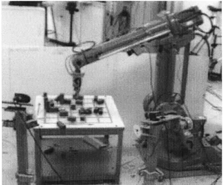
A new framework for controlling robots via the Internet has been designed and im-plemented in the Vision and Touch Guided Manipulation group at the MIT Artificial Intelligence Laboratory. This framework has been applied successfully to the problem of controlling the MIT Rover Test Bed- a small, tethered, wheel based mobile robot with two driven wheels in front, caster wheels in back, two passive cameras for stereo vision, and two arms. One arm is the first generation JPL Rocky7 rover arm on loan from JPL. The other arm is a four d.o.f. cable driven arm called the mini-WAM built by Thomas Massie as a small scale clone of the WAM robot built by Bill Townsend. The main features of the framework are it allows for great flexibility in the actual control strategy taken, and it allows transparent access to every level of the system through any computer connected to the Internet. Due to the fact that many "users" can access robot elements simultaneously, a priority based arbitration system is in-cluded in the framework to allow the system elements to filter conflicting inputs and operate in an orderly and effective manner. Potential "users" range anywhere from a behavior process running on a computer in Japan, to a person using a GUI to access the robot from the 9th floor of the MIT AI Laboratory.
Thesis Supervisor: J. Kenneth Salisbury, Jr. Title: Principal Research Scientist
Acknowledgments
At the end of the long road to thesis sits the tired student, grateful to the many individuals whom have contributed to this work, yet too weary to remember them all.
Thanks must go out to the many UROPs who have worked on the project, Sabina Ma and David Korka especially.
Thanks to Brian Anthony for all his help during my semester away and for making sure that I was not the last person in the office to finish my thesis. =)
Thanks to Ken Salisbury, my advisor for giving me the latitude to choose the direction of my research, and for providing the resources to carry it out.
Thanks to Eddy Baik for being a sincere person who cares about important things and constantly searches for the deeper meaning and purpose in himself, he is an inspiration.
A great big thanks must go to the most wonderful person in the world, Craig Lattimer. His friendship is priceless.
Thanks to my parents for raising me in a wonderful home and teaching me the timeless values that have helped me get this far, not merely in school but in life.
Most of all, I must thank my wife, for her unconditional love, support, and confi-dence, and the motivation to get this thing done.
Support for this work was provided by the National Science Foundation and the Jet Propulsion Laboratory.
Contents
1 Introduction
1.1 Motivation . ... 1.2 Problem Statement ... 1.3 Conventions used in this Thesis 1.4 Overview of the Thesis...
2 Overview of Previous Work 2.1 Web-Controlled Robotics .
2.1.1 The Mercury Project an( 2.1.2 Perth . ...
2.1.3 Berkley's Mechanical Ga:
i the Telegarden.
ze . . . .
2.1.4 Robotic Telescopes ... 2.1.5 JPL's Rocky7 ...
3 Design of the Arbitrated System 3.1 Overview . ...
3.1.1 Design Space and Design 3.1.2 List of Design Issues 3.2 Processing . ... 3.2.1 Possible Solutions . 3.2.2 Design Requirements . 3.3 Computing paradigm ... 3.3.1 Possible Solutions . Control Environment G oal . . . .
3.3.2 Design Requirements ... .. . 33
3.4 Documentation . . . . ... ... 33
3.5 Network accesibility ... ... 34
3.5.1 Should the system be web accessible? . ... . . 34
3.5.2 Possible implementations ... .. 36
3.5.3 Design Requirement ... .... 41
3.6 Robust error handling and Debuggability . ... 41
3.6.1 Possible Solutions ... ... . 42
3.6.2 Design Requirements ... .. . 44
3.7 Summary of Design Requirements ... . 44
4 ASCE Implementation 46 4.1 Overview ... . . .... ... ... 46
4.1.1 Why Java? ... .. ... . 46
4.2 The Mirror Subsystem ... ... . 48
4.2.1 The mirror model ... ... 48
4.2.2 How mirrors work ... ... 50
4.3 The Arbitration Subsystem . ... . . . 54
4.3.1 The Arbitration Model ... ... 54
4.3.2 How Arbitration Works ... ... 55
4.3.3 Shortcomings of this implementation .... . ... . 56
4.4 The Port Subsystem ... ... 59
4.4.1 How Ports Work ... ... 60
4.4.2 Issues in Process Flow ... ... 62
4.5 The ServoLoop Subsystem ... ... 63
4.5.1 Fault Tolerance ... ... . 64
4.5.2 Real-Time Support ... ... 64
4.6 The Behavior Subsystem ... . . . . 65
4.6.1 How Behaviors Work ... .... 65
4.6.3 The Behavior Manager ... ... 66
5 The MIT Rover Test Bed 68 5.1 Overview ... ... ... 68 5.2 Hardware ... ... .. 68 5.2.1 The Base ... ... . ... 68 5.2.2 The Arms ... ... ... 69 5.2.3 Vision ... ... 71 5.2.4 The Brains ... . ... ... 72
5.3 The RTB System Layout ... ... 74
6 Experiments 77 6.1 Overview. ... ... .. 77
6.2 Task Experiments ... ... 78
6.2.1 Early Sample Return ... .. . 78
6.2.2 Preliminary Subsytem Test Experiment . ... 81
6.2.3 Test on Rover Hardware ... .. 86
7 Conclusions and Recommendations 91 7.1 Summary ... .. ... .. 91
7.1.1 The Arbitrated System Control Environment . ... . 91
7.2 Recommendations and Future Work . ... 92
7.3 Conclusions ... .. ... 92
A Glossary 94 B Creating a Mirrored Object 96 B.0.1 How to create a mirror class. . ... 96
C Code for Selected Classes and Interfaces 100 C.1 asce.mirror.Mirrored ... ... 101
C.2 asce.mirror.Mirror. ... . ... .. 101
C.4 asce.arbitration.Arbitrator ... .. . . 112 C.5 asce.port.InputPort ... ... 113 C.6 asce.port.OutputPort ... .. ... .. 116 C.7 asce.port.PortManager ... ... 116 C.8 asce.port.PortOwner ... ... 117 C.9 asce.behavior.Behavior ... ... .. ... 117
D Where to find more information. 119 D.1 Online docs for the RTB system ... . . 119
List of Figures
2-1 Shown here is the famous Internode Systems SNMP Controlled toaster. 17 2-2 The Mercury Project at USC let web users move the robot and blow
air to uncover clues in a sandbox. ... . 19
2-3 The Telegarden allows web users to plant seeds and water them and is currently on display in Ars Electronica Center. . ... 20
2-4 The Perth Robot at the University of Western Australia. . ... 20
2-5 Shown here is a screen shot of Perth's Web User Interface. ... . 22
2-6 Here is Perth placing a block under command of the author. ... . 23
3-1 The merging of top-down and bottom-up design modes. . ... 27
3-2 An illustration of the Mirror Paradigm. . ... 39
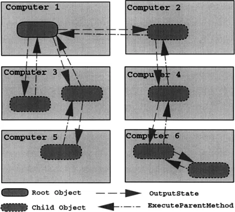
4-1 Shown here is a possible mirror tree. Notice that there is no conflict with having two mirrors for the same root running on the same com-puter as long as they have unique names. In general this is not a very efficient way to do things, however. . ... 49
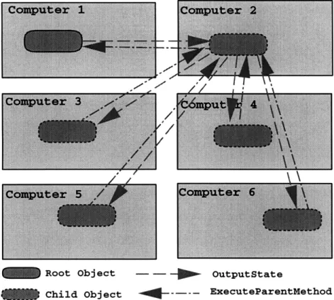
4-2 A more efficient layout for the mirrors. . ... . 50
4-3 An arbitration example. ... ... 57
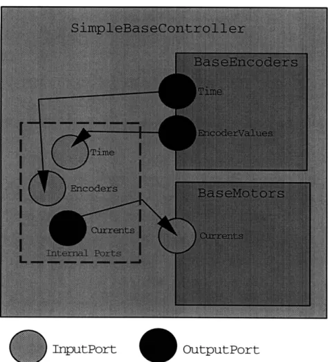
4-4 An example of external or public ports vs. internal or private ports. The BaseEncoders and BaseMotors objects are shown inside the Sim-pleBaseController because it abstracts them. . ... 61
5-1 The rover before the miniwam was mounted. The two sphere were used in a behavior that would visually servo the rover to a lander mockup
using the overhead camera. ... ... 69
5-2 A close up of the drive system ... ... 70
5-3 The JPL arm ... ... 70
5-4 The mini-WAM before it was mounted on the rover. . ... 71
5-5 The rovers cameras ... . ... .. 72
5-6 Some of our Computers ... ... ... 73
5-7 A layout of the RTB System. Note that only a few components are shown, dashed round rects represent object mirrors. . ... 75
6-1 One run of the Behavior Arbitration and Port usage experiment. .. . 83
6-2 There was obvious human involvement here. One incarnation of the SimpleBaseControllerGUI is shown. . ... 84
6-3 The path of the simulated rover in a walled-in test. This shows several simple elements working together to create complex behavior .... 86
6-4 A Walled-in test with the RandomTurnBehavior disabled. . ... 87
6-5 Shown here is the view from the left eye as the rover visually servos on the green ball. The buttons at the bottom are for selecting the channel and choosing the color to look for. . ... . 88
6-6 Shown here is the rover as it visually servos on the green ball .... 89
6-7 Shown here is the state of the BaseMotors object just before the AvoidObstacleBehavior takes over. . ... 89
Chapter 1
Introduction
This thesis presents the design and implementation of a new framework for controlling robots via the Internet. This framework has been applied to the problem of controlling the MIT Rover Test Bed- a small wheel based mobile robot with a simple vision system and two arms. The main features of the system are that it allows for great flexibility in the actual control strategy taken,(eg. centralized, distributed, behavior-based, etc.), and that it allows transparent access to every level of the system through any computer connected to the Internet. Due to the fact that many computers can access robot elements simultaneously, a priority based arbitration system is included in the framework to allow the system elements to filter conflicting inputs and operate in an orderly and effective manner.
Most current web-based robotic systems have a very clear line where the robot system ends and where the user-interfaces begin. This line is the web server that interprets commands received from remote users on the internet and issues commands to the actual robot. An analogy of this type of system is a radio station playing requests that listeners call in. The framework developed in this thesis blurs and maybe even eliminates that line by allowing remote "users" to interact with every level of the system, allowing them to actually become part of the system, rather than only allowing access to a graphical user interface (GUI) which has limited interaction with the rest of the system. The intent of this thesis is to contribute this new approach to the body of knowledge dealing with web-based robotics.
This chapter contains a section on the motivation for this research presented anecdotally in the first person, a section with the problem statement, and concludes with an overview of the remainder of this thesis.
1.1
Motivation
This thesis comes as the result of my desire to create a robot programming envi-ronment with more flexibility, ease of use, maintainability, accessibility, and stability than what I had been using in the past.
When I started working in the MIT Artificial Intelligence Laboratory, I began working on the Whole Arm Manipulator (WAM) used in conjunction with the Fast Eyes Gimbals (FEGs) to grasp cylindrical objects lying on the floor. The arm and eyes were controlled by a VME-bus based system running a one of a kind operating system developed by Gunter Niemeyer called Hummingbird. This system has been able to do some very impressive things such as catch a free-flying tossed ball, and more recently, catch paper airplanes.
While this system was very fast and could perform these impressive feats, one had to be a skilled computer hacker to program the system to perform new tasks. This was in part because the system had evolved over several years under the guidance of different programmers. It was fairly complicated, involved several different types of hardware, and lacked in-depth documentation.
I do not mean to imply that things had not been done correctly on that system,
for this would be very far from the truth. Two of the main programmers who have worked on the system over the years Gunter Niemeyer, and "Jesse" Won Hong, are easily among the most talented engineers I know. They knew the system inside and out, and in an evening of hacking could do marvelous things. The problems arise when a neophyte to the system comes along and tries to start programming it.
A critical point to note about the WAM system, is that in fact it is a research project, not an industrial project. The latter is a very different beast, often with huge staffs to design and implement standards, review code implementations, maintain past
code and produce future releases. University research, on the other hand, is made up of researchers often with a handful of over-worked grad students trying to push the limits of technology in very specific areas. Trying to get a demo working to show some new capability or a proof of concept to funding sources is the par. At that point no one really cares about the maintainability and extensibility of the system, they only care about whether it works or not.
When I was given the opportunity to put together a robotic system from scratch, I took it as an opportunity to try to design and implement a system with some of the features that I had longed for during my previous work. I wanted to create a system that was easily programmable, highly documented, modular, and easily extensible. In t he summer of 1996 I co-authored a paper called "Autonomous Rock Acquisition" for an AIAA conference in August 1996. In this paper I presented some of my ideas for the design of a hybrid system combining benefits of both distributed control and centralized control which I called "Augmented Distributed Control." I presented a list of desirable qualities for that system. That list follows:
1. Complete autonomy in the execution of very high level commands.
2. Robust error handling and recovery built in.
3. Easy to program, natural task representation.
4. Abstraction of detail, hardware independent.
5. Able to carry out useful work even in the absence of high level commands, eg. default behaviors.
6. Able to carry out tasks in parallel.
7. Able to handle redundant sensors naturally.
8. Able to handle redundant processors naturally.
9. All elements allowed access to a centralized world model.
11. Elements can come on-line or go off-line in real time.
12. Allows for centralized control when desired.
Now, nearing the end of (the first phase of) this project, I am pleased to realize that the system I have designed and implemented addresses every one of those desireable qualities with only slight modification. (Specifically, the centralized world model became an element which could exist as part of the system, but is not required.) I will discuss this in conjunction with other approaches taken in robot control in the next chapter. As the project progressed, I began to see the potential of using the web to help accomplish some of these original goals and steered the project in that direction.
1.2
Problem Statement
This thesis most neatly falls into the category of a system design project. The intent was to develop a framework, mostly in the form of interfaces and helper classes, that will, in the future, be of use to people working on the MIT Rover Testbed (RTB) or other robotic projects.
The first step taken was to come up with a specific list of desireable attributes, or more formally, design requirements. This step included a large amount of design ex-ploration as well as significant trial and error in test implementations using different programming languages, hardware, etc. The next step was to come up with a possible design solution that met the established design requirements. This, as every designer knows, is an exercise in trade-offs and compromise. Following this decision making process a working implementation of the framework system was created. The frame-work was then tested by using it on a real robotic system, the MIT Rover Testbed, where sample controllers and behaviors where implemented using the framework.
1.3
Conventions used in this Thesis
Due to the large number of acronyms and technical words used in this thesis, a, glossary has been included in Appendix A, and an effort has been made to include all words that might be found troublesome to the reader without background in robotics and Java programming.
The code for this thesis was written primarily in Java, and hence some expla-nation of Java conventions would be useful. The Java language, developed by Sun Microsystems, is an object oriented system similiar in many ways to C++, but also very different. Java is bot a compiled and an interpreted language. Java code is first compiled into bytecode, a machine independent code, and then the bytecode can be run by an interpreter on many different operating systems. Java has a strict conven-tion on the naming of classes and interfaces, which should be included in packages. A package is a grouping of classes and interfaces with a common purpose. Each class or interace must be defined in a seperate file carrying the name of the class it it defining, and that file must be stored in the correct directory for its package. For instance, "asce.mirror.Mirrored" is the full package name for the Mirrored interface which is defined in a file called Mirrored.java which is saved in the "/asce/mirror" directory. If this seems unclear, there are several books on Java which explain it in detail.
Java classes will generally be referred to by their full package name to avoid any possibility of confusion. Methods (functions within a class or interface) will be referred to by the class's full package name followed by a colon with the method name unless the class is clear from context, (i.e. asce.mirror.Mirrored:stateChange). Most of the references to classes and methods will point the reader to the corresponding code in the Appendix C.
The word "user" will refer to both humans and other objects or processes which might make use of a particular system element. For example it is possible for either a behavior running on a computer or a human operator to take control of part of the robot.
1.4
Overview of the Thesis
Chapter 2 explores some of the projects that have been done in the area of web controlled robotics. It discusses the general strategies taken, and how the work in this thesis differs.
Chapter 3 presents the major issues that were considered in the design of the Arbitrated System Control Environment (ASCE). Its sections explore each issue in detail, offering several possible solutions and choosing one for implementation. The last section in chapter 3 summarizes this information with a concise list of design requirements and coresponding design specifications.
Chapter 4 presents the interfaces and subsystems implemented to meet the design requirements presented in chapter 3. Each subsystem is presented in turn, followed by an integration section presenting an example of how they all work together as a complete framework for web-based robotics. In addition, chapter 4 has a brief discussion of why Java was chosen as the primary language in which to implement the framework.
Chapter 5 presents the MIT Rover Test Bed (RTB) in detail and discusses the application of the ASCE framework to it. The first part of the chapter gives an overview of the hardware, and the remainder is devoted to explaining the java package written to run the robot which is named rtb (lower-case package names are another java convention).
Chapter 6 presents some sample behaviors that have been implemented using the system, mentions some issues that haven't been dealt with directly, suggesting possible solutions, and concludes with some recommendations of behaviors that would be useful or interesting for future research.
Chapter 7 presents the onclusions and some suggestions for future work.
The appendices contain a glossary of terms and acronyms used in this thesis, a mirror programmers guide for additions to and maintenance of the system, various code listings referred to in the text, and a list of sources for more information on Java and the ASCE framework.
Chapter 2
Overview of Previous Work
The first part of this chapter explores some of the projects that have been done in the area of web controlled robotics, the remainder of the chapter is devoted to a discussion of previous work in the area of robot control strategies.
2.1
Web-Controlled Robotics
Probably due to the great success and popularity of the internet over the past few years, we have seen the birth of a new type of mechanical device. These new devices might be best classified in the broad category of web-controlled robotics. The first such devices were pure novelty, however, this class of device seems to have left the embryonic stage and is now in very early infancy as demonstrated by some of the newer telescope and rover projects. These newer projects take the novelty of web-controlled robotics and turn it into a tool for sharing scarce scientific resources with a vast global audience.
Some of the early and more well-known web-controlled robotic devices are listed: 1. The Mercury Project and the Telegarden at the University of Southern
Califor-nia.
2. The Perth Telerobot in Australia. 3. The Mechanical Gaze at Berkley.
Figure 2-1: Shown here is the famous Internode Systems SNMP Controlled toaster. 4. Various Robotic Telescope Projects.
5. The Rocky7 rover at the Jet Propulsion Laboratory.
While there are probably many other systems out there, both on-line and under development, the intent here is to show some examples of related work and a broad view of the current state of web-based robotics. For interests sake, other than the systems listed above, a web-search turned up "The Internet Toaster", various remote cameras, and a web controlled model railroad in Germany. The Internet Toaster (Figure 2-1) is claimed to be the first web-controlled mechanical device. While making web-toast may not seem like a particularly useful thing to do, it was demonstrative of some of the possibilities of the future internet.
All the systems found to-date are very similar in that they have some way to command the robot's new position, and provide still-frame visual feedback once the move has been made. All systems present the user with some sort of GUI to control the robot, but there is no opportunity to retrieve lower-level data from the robot, program the robot, or extend the system. This is the area to be addressed by this thesis. The difference is mainly that these systems are set up such that there is a robot with a control system, and then a subsystem is added to allow high-level control via the web. On the other hand, the system developed in this thesis is completely integrated with the web, and the web is essentially part of the robot.
2.1.1
The Mercury Project and the Telegarden.
The Telegarden is the direct offspring of the Mercury Project, which was one of the earliest truly interactive web-robots. It was conceived and developed at USC, both as a novelty, and a way to study how the internet community interacts with each other. The robot used was an old industrial robot that they had in the lab. The goal was to create a system which the internet community could actually use to modify the environment in some way. However they found it difficult to conceive a system that would allow for only non-destructive interaction with the environment.
Eventually they came up with the idea to remove the robot's end-effector and, replace it with a pneumatic supply hose which could give a burst of air when desired. The workspace was filled with sand, and clues to a story where buried in the sand. A picture of the robot appears in Figure 2-2. Users were then able to take turns moving the robot, blasting some air, and seeing what, if anything, was buried in the spot they had chosen. There was a newsgroup provided where people could post what they had found, and share their theories about what the clues mean. The site was very popular making it difficult at times for users to get on the system.
The success of the Mercury Project inspired the designers to create a new web con-trolled robot which would offer more opportunity to study how the world-wide internet community interacted. In the Telegarden (http://www.usc.edu/dept/garden/), the robot's workspace was filled with dirt. The robot was able to plant seeds by blowing a hole in the dirt, then dropping the seeds in, as well as water the seeds and plants in the workspace. See Figure 2-3. They have had to wipe out the garden and start from scratch on several occasions, due to the fact that everyone wants to do something, and plants only need so much water. They have addressed that problem in part by limiting the amount of water used.
The questions raised here are, (1) how do you know that Joe User's intentions are constructive rather than destructive, (2) how to limit the amount of damage possible if they are destructive, and (3) how to provide enough information about the current state of the garden so that he can make good decisions if his intentions are good. They decided from the outset of the project that if anything were to be learned from
Figure 2-2: The Mercury Project at USC let web users move the robot and blow air to uncover clues in a sandbox.
the project that there would have to be the possibility of failure. This is because if success is guaranteed, eg. if the system kept track of how much water each area needed, and only allowed that much, as well as watered those areas itself that where neglected, then the community becomes entirely unnecessary. Obviously eliminating system dependence on the variable of interest (the community) does not facilitate study of that variable.
2.1.2
Perth
The Perth telerobot is located at the University of Western Australia, and can be found on the web at:
http://telerobot.mech.uwa.edu.au/.
It consists of an industrial robot positioned over a table with wooden blocks. The author was able to log on to the Perth system and control the robot for about a half an hour. A color image of the robot is presented in Figure 2-4. There were
Figure 2-3: The Telegarden allows web users to plant seeds and water them and is currently on display in Ars Electronica Center.
approximately 600 sessions per week in 1996. The robot allowed a single user to take control at any one time on (what seemed to be) a first come first serve basis, although preference was given to people who filled out their online survey.
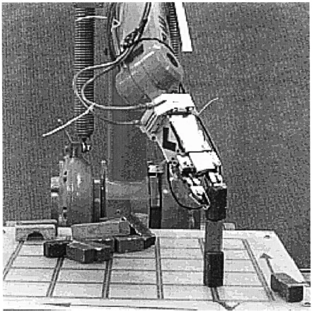
Once a user had control of the robot, s/he was presented with the user interface shown in Figure 2-5. It allowed for simple control of the robot by specifying the new x,y,z,tilt and spin coordinates of the end effector, and whether the gripper was opened or closed. The other option was to specify sequential moves, e.g. "open z10 close z100 y70 open." It was a rather unnatural and slow way to carry out a task, but with a little effort the author was able to successfully stack three blocks on end as shown in figure 2-6. Later the same day, the robot was found in a state where joint 6 was at its limit. After quite a while of trying to back away from the limit, the author conceded defeat. It seems that the robot is programmed with restricted movement in cartesian space, as it will not accept a command to move the end effector out of a 500X500X450 unit cube. However, there is no guard against moving to joint limits, and hence the robot can get stuck in a position which is difficult to back out of.
Most likely due to the difficulties of controlling the robot by typing in numbers, Perths caretakers are developing a Java applet which shows graphically where a given command will move the robot. It is assumed that eventually they will be able to drag the graphical end effector to the desired position which then commands the actual robot to the same position. This would be an example of a predictive display. Note that this applet is being added to the user interface as a visualization tool, and is not a direct part of the robotic system. In the system developed in this thesis, the goal is to provide for simple integration of such components directly into the system.
2.1.3
Berkley's Mechanical Gaze
Berkley's Mechanical Gaze can be found at http://vive.cs.berkeley.edu/capek/. Even though the web page claims continuous operation since March 1995, they have been moving the robot to a new location, and hence it has been unavailable for exploration. The idea of the robot is to provide a camera mounted on the end effector that can be used over the web for exploring a remote space. The project engineers set up a
O.S,,
OtO
o
Entsr aset .:,ves ae (exa.ple "c pi zIC ,:,:e z100 :, ,pn'
:F A
c or peco -oly .e next pc It]on e arUd or Ie.tacn o of th: gripper
Gripper opI : Y: Z:
Spin:
.a
Tilt:211
M ove reCotL.Figure 2-6: Here is Perth placing a block under command of the author. small museum display with interesting objects to look at. In scanning through the comments there seemed to be many people who had trouble controlling the robot, or getting a picture, but others found the robot to be very usable and interesting. Email had been sent to the engineers asking for information on challenges they have had and things they have learned, but they had not responded at the time of this printing.
2.1.4
Robotic Telescopes
There are currently a few different robotic telescope projects out there either in operation, or under development. These are in the most basic case servo-controlled two degree-of-freedom telescope pointers coupled with a camera. The idea here is that not everyone can afford a full scale telescope of their own, but that there are many telescopes out there that are only used a small fraction of the night hours in which they are useful. One way to make better use of the resource is to allow people
to go to the site and use the telescope in what would otherwise be downtime. This requires that people travel to the site which is expensive and time consuming, and also requires people to conform their sleep schedules to the available observatory time. The better option (now that it is possible) is to create a web-based interface which allows remote users to request and schedule use of a telescope, and retrieve the images via the web.
One such system is the Bradford Robotic Telescope Observatory, which can be found at http://www.telescope.org/rti/use.html. It claims to be "The first of its kind in the world." Information presented on the web site contains the following expla-nation, "The Bradford Robotic Telescope is 46cm and totally autonomous. Located high on the moors in West Yorkshire, England. The telescope decides when the con-ditions are good enough to make observations of the sky by itself (an astronomer does not need to be present). Anyone on the Internet can register and ask the telescope to look at anything in the northern night sky. Observations are automatically prioritised and scheduled and completed by the telescope as time allows. Other data (weather information and reports) are obtained and updated on this site automatically every day. The telescope and this system are prototypes. We are currently working with a number of schools and institutions to provide telescopes similar to this around the world." Currently the Bradford Robotic Telescope allows anyone on the internet to make use the telescope on a first come first serve basis and the system can handle a maximum of 160 simultaneous web requests.
One of the predominant research issues involved in the web-based-telescope con-cepts deal with optimum scheduling of resources. For example, if there are many requests for a single night with various targets, what trajectory should the telescope follow through the night to satisfy as many of the requests as possible.
2.1.5
JPL's Rocky7
Interestingly the Rocky7 project at JPL turned to the web concurrently and inde-pendently from the project at MIT. The approach taken, however, was necessarily different. The web interface is a collaborative development between Jet Propulsion
Laboratory (point of contact: Paul Backes) and IA Tech, Inc. (point of contact: Kam Tso). The Web Interface for Telescience (WITS) is a subsystem that was added to the original system to allow users of the web to use the robot from their home institutions rather than having to travel to JPL. It is not directly "connected" to the rover as it requires that the engineering team uplink the final plan to the rover. In contrast, the approach taken in the. MIT project was to create an experimental system completely connected to and integrated with the web, allowing for the easy creation of user interfaces and hardware sharing as part of the basic system rather than adding these amenities as subsystems.
The WITS user interface is available on the web at:
(http://mars.graham.com/rocky7wits/index.html).
It runs a simulation of the rover as it is mainly for public outreach, and therefore does not have to deal with issues of unauthorized use and prioritized distributed control. In the mission version which will actually be used to command the robot during tests or on Mars, user access is controlled by IP address and password protected user login. All users who log into WITS have a user type: Scientist, Navigator, Viewer, or Mission Planner. Scientist, Navigator and Mission Planner users can modify the common database at JPL which contains plans for future rover tasks, and all users can see what other users submit to the plan. Currently it is up to the principal investigator to decide which requests are put in the plan and provide the final plan to the engineering team for uplink to the rover.
Chapter 3
Design of the Arbitrated System
Control Environment
3.1
Overview
This chapter presents the major issues that were considered in the design of the Ar-bitrated System Control Environment. The balance of this section contains some comments on the design process in general, a definition of the design space, and a list of the issues considered. The following sections explore each issue in detail, offer several possible solutions and choose one for implementation. The last section sum-marizes this information with a concise list of design requirements and corresponding design specifications.
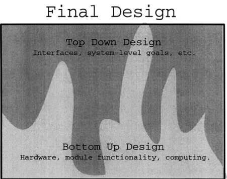
The growth and development of this system specification or design can best be modeled as an evolutionary process rather than a strict design methodology. It cannot be classified as purely top down, or bottom up. It can most accurately be described as a bottom-up idea - implementation - revision cycle in parallel with a top down idea
-implementation - revision cycle, the two generally meeting somewhere in the middle. Some of the top down elements end up filtering all the way through the system to the bottom, and some from the bottom to the top. A graphical representation of this process is shown in Figure 3-1.
Final Design
Figure 3-1: The merging of top-down and bottom-up design modes.
the resulting system, however, this is a research project and hence the exploration of new technologies and new ways of doing things has taken precedence over finding the most direct and cost effective way to get from point A to point B. For instance, the use of Java as the main programming language of this system, even for the low-level controllers, might not make sense from the standpoint of creating the best control system. On the other hand, it provides a convenient way to create a homogenous system which facilitates the meeting of other design requirements such as providing runtime access to every level of the system. More on the justification for using Java will be presented at the beginning of the next chapter. The point to be made here is that the design tradeoffs made in this project are most likely very different from those that would be made for the same project in an industrial setting. Simply put, the focus here is exploration and not necessarily a finished product.
3.1.1
Design Space and Design Goal
Determining the design requirements can be vague and confusing without a well defined design space. The design space for this project consists of one to several computers working on a high-level common goal (or set of goals) possibly with specific
---hardware connected to individual computers. The design space is further divided temporally in two subspaces: programming-time, and run-time. Programming-time includes time spent on maintenance, debugging, and extending the system. Run-time is what the system should be capable of doing. The design goal for this project is an error-tolerant system that is easily accessible, extensible, and maintainable, and capable of carrying out complex high level goals. A test platform for the design implementation is the MIT Rover Test Bed.
3.1.2
List of Design Issues
The following is a list of various issues, options, and problems that have become apparent in reaching for the design goal in the design space. Each will be discussed in the following sections. These issues tend to be very inter-related, and as always, this forces design tradeoffs. The tradeoff debate could resemble the following dialog. "The system should run fast, the system should be object oriented, and highly general. However, generality often precludes optimum efficiency and therefore it must be asked how fast is fast enough and how general is general enough?" Many of these questions can only be answered in the qualitative realm of opinions based on personal experience where a typical decision will be to sacrifice a certain amount of speed in favor of generality and visa-versa. The issues specific to this project follow. They will be discussed in reference to the general design goal, and occasionally comments will be added relating to the specific system requirements of the MIT Rover Test Bed.
1. Processing: How to meet the processing requirements.
2. Computing paradigm: What general approach should be taken? Linear pro-gramming, object oriented, text-only, or graphical?
3. Documentation: How to make sure it is well documented for future use and modification.
4. Network Accesibility: What level of network access should be allowed and how to achieve it.
5. Robust Error Handling and Debuggability: How to avoid having one error bring the system down, and to make it easy to track down errors and fix bugs.
The remainder of this chapter will explore several key design issues, and present some main points of the evolution of each design requirement.
3.2
Processing
The first question to be asked when doing a computer-related project of this type is "what type of computing system will be used to do the processing?" The answer to this question unfortunately tends to determine many of the future design decisions because of the capabilities and limitations of the platform or system chosen. Another reality of choosing processing options is that while computers are very cheap compared to what they have been in the past, they are still not "a dime a dozen" and hence new projects must often make use of whatever computers happen to be available.
Another issue is how to add more hardware to the system? Suppose that a robotic system is setup on a VME bus, and the project needs another frame grabber, or controller, but all the slots on the VME bus are filled. It would be ideal to be able to add hardware as needed, allowing the system to grow and scale naturally without having to recreate the entire system every time a limit of the current setup is encountered.
3.2.1
Possible Solutions
With these issues in mind, the ideal solution seems to be to design a system that can make use of whatever processing is available. In other words, a platform independent system. Of course, complete platform independence is not currently possible whenever a computer is used to control specific hardware, as device drivers specific to that computer are needed. However it is possible to create a level of platform independence by creating device drivers that have a standard interface to the higher levels in the system. Using this approach, the majority of the code that is written can be platform independent using any standard language that can be compiled on most computers.
Of course, platform independence is taken to an even higher level with an interpreted language that does not need to be recompiled for each computer, languages such as Lisp, or Java.
The issue of adding new hardware to the system brings up the question of how to communicate between the different parts of the system. The only way to provide for total flexibility, as well as hardware independence, is to connect the processors through a standard that any type of computer can connect to. Such a standard is Ethernet using TCP/IP. Using a networking solution such as this has several tradeoffs. Currently, it limits the ability of the system to directly share memory or to have high-bandwidth communication. However this is not a real problem for a system that operates more in the range of distributed control rather than centralized control. Also, because the specific system we are designing for here, the MIT Rover Test Bed, is a system that will interact with an essentially static environment, there is no compelling reason to sacrifice system generality for speed of inter-node communications. In addition, specifying that the system nodes communicate via Ethernet by no means precludes the possibility of adding subsystems such as a VME bus, and in the most general case allows for the inclusion of every computer on the internet in the system. The discussion of the communication protocol could go much deeper here as there are different standards for sockets that handle lost packets and error checking differ-ently. When dealing with a tele-operated robot, in general it is not advantageous for the robot or controller to request that a lost packet be resent because by that time the information will be old and not nearly as useful as if the lastest information were transmitted instead. However in a general system such as is being designed here, there are many cases when a single message could be very important and therefore should not be' dropped. Probably the best system would allow for both types of connections to be made. However, for system simplicity, it is easier to simply use a standard that gaurantees the (eventual) arrival of every packet sent, or generates an error if the connection is lost.
3.2.2
Design Requirements
The design requirements arrived at in this section are that the system be programmed primarily with platform independent code and that processors or computers are con-nected using standard ethernet using some standard socket protocol.
3.3
Computing paradigm
Should the system be object oriented? This is a question with clear tradeoffs. On the one hand object oriented languages are typically slower than non-object oriented languages. On the other hand, object orientation brings with it many of the other design requirements discussed in this section. For example, object oriented languages in general make it easier to write code which is reusable, maintainable, extensible, and debuggable. In addition some offer convenient documentation aids which greatly simplify the documentation process.
3.3.1
Possible Solutions
It seems clear that object oriented is the way to go. In places where speed becomes critical, there is ussually the possiblity of writing that bit of code in C or Assembly, and then linking it into the rest of the code. Once the decision to use an object oriented paradigm is made, the next question is how to represent the system symbol-ically, and to what level of detail.
One option is to write the code with an object to represent each physical element of the system. For example, an object to represent the robot's arm, one for the base, one for the cameras. One benefit of this approach is that it allows the possibility of creating high level commands which abstract away all the detail of implementation. For instance, I could ask the cameras object if there is a ball in the workspace by calling a method like ball = findBall(). If findBall returns with a ball I could then call a gotoBall(ball) on the base object followed by a grabBall(ball) method on the arm object. This provides an easy way to implement high level behaviors, and lends
itself towards the implementation of a scripting language approach. The scripting language idea is nice because it provides a way to script out new sequences of actions without having to write and compile any new code.
One drawback to the method just expalained is that implementing the individual objects becomes a difficult task because of their size and complexity. For example, the base object needs to have methods to access the encoders, and to output currents to the motors. It needs to implement a controller, a trajectory generator, a trajectory spooler, and probably some kind of navigation. Another complication is that at different times, it might be desireble to run the base in different modalities. For instance one might need to be able to navigate both in absolute and relative frames. For example:
1. goto(x,y,theta) meaning move the base to absolute position (x,y) pointing in direction theta.
2. moveForward(x) meaning move forward relative distance x.
3. moveWheels(leftWheel, rightWheel) meaning move the wheels to the absolute angles specified.
These are just a few of the commands which might come in handy for navigation purposes, and they are very different in their implementations. The first requires inverse kinematics computed for the base to figure out how to get to the point specified by driving the wheels. This non-holonomic problem can be quite complex and involved especially when things are added such as obstacles.
Another drawback becomes apparent when thinking about modifying or extending this object. First of all, this would be impossible in real time while the system is running. It would require bringing down the system, writing all the new code, and then starting it back up. In addition, adding new methods or functionality to an object of this size becomes a problem because it is not only possible but likely that the currently functioning object will in some way be broken. Changing some aspect of the controller code may very easily break code that was tuned to how the controller used to respond. Maybe it would be possible to write new controller code while
leaving the old intact, and providing some way to switch between the two. While this is a possible solution, it adds additional unnecessary complication. However, it does hint at another possible solution to the problem: decreasing the grain size of our objects.
Another design option would be to have computing objects representing a finer grain size of the physical system. For instance, instead of having one large object representing the base, there could be an object representing the base motors, one for the base encoders, one for the controller, etc. One could then create a base object which provided the type of interface explained above by incorporating these sub-elements into it, essentially wiring them together for a particular function. However, it would not preclude the programmer from making use of the lower level elements directly when desired. This creates a multilevel scaleable environment where the programmer or user has access to elements on whatever level is necessary, while unnecessary detail is abstracted away by the higher level groupings of objects.
3.3.2
Design Requirements
The design requirement is a scaleable component based system. For example, detail should be hidden when desired by working with the Arm component as a complete entity. When it becomes necessary to delve into more detail, you can get a list of components contained in Arm, and deal with them directly. This list might look something like this: ArmEncoders, ArmController, ArmInvKinematics, ArmMotors, ArmTrajPlanner, etc. Each of those in turn could contain sub components or be a base component where actual computing takes place. Every component will have a list of input and output ports which can be wired together and should be type checked for compatibility.
3.4
Documentation
One of the keys to survival for software written in the university research arena is good documentation. There is obviously a high turnover of personnel (students) and
thus, for a project to have any continuity, the software must be documented at least well enough for the next student assigned to the project to be able to take it over without having to start from scratch.
What often happens is that a programmer, in a hurry to try to get a demo working, will not document the code thinking that when done s/he will go back and comment it all. This rarely happens. Hence many functions are known only to the original programmer, and there is no way to find them out short of digging through the code. What would make it as easy as possible for the programmer to effectively comment the code? One help is automatic documentation generators. There are many software development tools which facilitate the documentation of code. By using a standard format for comments in the code, an application can process the text of the code and produce a document or web page presenting the available functions along with the programmers comments in a logical way. This should clearly be standard operating procedure in any large software project. The Java language has such a tool called javadoc which can automatically document code in the form of web pages.
3.5
Network accesibility
3.5.1
Should the system be web accessible?
What benefits can be gained by making a robotic system network accessible? This question came up several times from several sources during the evolution of this project. For an experimental system, one might think that the programming overhead to make a system web accesible could not be justified- especially since it would also consume considerable cpu time during operation. However, CPUs have become fast and cheap, so eating up processing power is not a huge problem. Perhaps the bottom line is that now there is really no reason not to provide for network access (barring security considerations). While the tradeoff is a real one, a simple answer might be: "if it is running too slow, add another CPU."
mon-itor what is going on in there. While debuggers can help you step through the code, this is not really helpful in a real-time system that has many inputs and outputs. For example, suppose one writes a piece of code to find the home position for an arm by finding the joint stops of each joint in turn. When the code is run, the arm freaks out... This can be even more of a problem when the code is running on a processor
with a tight servo loop and no time to spare to output debugging information. This design solves this problem by requiring complete object state to be broadcasted each time there is a significant change. In this way, the system is built with the debugging overhead built in, and hence, saving it to disk or monitoring it from another computer becomes trivial.
Another issue is that of toggling or fiddleing with parameters. This is usually very hard to do in real time. However, by allowing access to all objects, the user is not restricted to only the monitoring of their state, but may change their state or parameters in real time.
There is also some precedent for web accesible robotic systems as shown in the survey chapter.
The programming time to implement such a system could be done in such a way as to abstract away most of the network issues making programming of the system quick and straight-forward. Once the work was done, it would not have to be repeated for each new module. Hopefully it would begin to set a standard that network accessible
systems in the future could build upon.
NASA/JPL has shown interest in making their experimental robotics network accessible by providing some net access to their Rocky7 prototype. This can provide scientists with the opportunity to perform science with the robot without having to travel to JPL and sit down at their control station. It makes little sense in this day of the GUI to create complex specialized hardware controls (ie. control panels layed out with buttons and monitors) when all this can be done with a well-planned GUI and a mouse, joystick, 3d mouse, spaceball, head-tracker, or any other of a myriad of standard input devices.
robotics, making the system web-accessible also seemed to be a good move in the area of public relations. Allowing citizens to log on and experience some aspects of the rover will hopefully increase public awareness and support for space exploration and science in general.
3.5.2
Possible implementations
Assuming that web accessibility is a desireable thing, what are the different ways it can be achieved and which will be most successful in helping to achieve some of the other goals stated for the system?
This project, as almost every design project, has been an evolution. Starting with a few vague ideas of how the system should be, the system specification progressed through several stages of network accesibility. Actually, network accessibility was almost an afterthought, but after many design -implementation -evaluation -redesign cycles, the possible benefits became clear and it became an integral part of the system. It was hoped that the specification that came out of this project would be general enough to be applied to other systems. This follows from the idea that it should be possible to abstract away the majority of the networking/ distributed computing overhead, and provide a simple interface to the network and the power of distributed computing. Network computing is still in its infancy, but the infancy is nearly over as international standards are being set, paving the way to a world-wide open computing environment. Following are several possibilities for taking advantage of this world-wide environment at different levels.
Simple Socket Connection
In one of the early incarnations of the RTB system, the control code was written in C++. It implemented a socket connection to which a user interface running on another computer could connect. The user interface could then send simple text-string commands to the system to get it to do things such as move forward, turn right, lower arm, etc. While this type of arrangement would seem at first glance to satisfy much of what was wanted in terms of network accesibility, namely allowing people
to interact with the system from anywhere in the world, it presents inconveniecences which became apparent while using the system.
The first inconvenience is that in this simple message passing system, it is nec-essary to change the code of the server running the system everytime one wants to add a new command. This involves stopping the server, adding the appropriate code, compiling, and restarting. In many cases, this requires the person wishing to add the functionality to have physical access to the computer running the code. This would make it difficult to expand the system remotely. In addition, due to the fact that the server has to be aware of every possible message and how to handle each, as the number of different messages gets large, the code can get large, messy, and unmanageble. This clearly violates some of the desired characteristics of the system,
specifically, easy maintainence and extensibility.
The second inconvenience is using this type of system, it is impossible to interact with the system at the level needed for progress to take place. With a message passing system, it is difficult to provide coherent access to anything but the high levels of control on the system. However, it is often very desireable to go in and change a gain in the control law for one of the wheels on the robot, or to slightly modify some parameters the vision system is using to detect interesting objects. Accounting for all these possibilities ahead of time and creating a workable messaging system to handle all of them is a very difficult proposition. A simple message passing system does not have the generality desired.
Remote Interfaces for each object
When it became apparent that writing one message server to handle all the commu-nication from the computer running the hardware to the outside world was not an optimal solution, a new approach was taken. This new approach was to create a sys-tem in which each code object provided for its own network interface. This eliminated the problem of having to maintain one "all-knowing" server, and each computing ob-ject could provide as many options to the remote computer as necessary. This would make it possible to get at all levels of the system. Dr. Salisbury advised on occasion
that "No matter how intelligent your system is, the scientists or engineers are going to want to be able to get in there and command a finger to move, or to twiddle bits." It seemed that as long as each object provided a fairly comprehensive interface, this requirement could be met.
This was done in the Java programming language using RMI (Remote Method Invocation), which provided a fairly straight forward way to define a remote interface for each object. The remote interface would define a set of methods that could be invoked over the network. This provided a way to implement all the network functionality desired on every level.
A problem started to become apparent as several objects were implemented using this strategy. When routing all messages through a single server, it was possible to do some arbitration between inputs. The issue here is that when a robotic system
is web-accessible, the possibility of receiving conflicting commands is very high. One user or "behavior" running on a computer may want the robot to move forward, while another wants it to move backwards. This problem could be solved in the single server model by simply assigning priorities to each user or behavior (based on some rule or table) when the socket connection is made. Then control of the system would be given to the connection with the highest priority, and would not be given to another until yeilded or until the connection was dropped. In the model where every object implemented its own web interface, every object and method had to take care of all that arbitration by itself. It began to appear as if the overhead required for allowing such complete web access to every object was excessive. Was there any way to abstract all that overhead and implementation detail away so that when programming, one could concentrate on making a robot system that used the web as a tool rather than making a web system that incedentally controlled a robot?
The Mirror Paradigm
An idea for a new paradigm for the system was borrowed from the web and several FTP and HTTP sites that had download links annotated with something like, " if download is too slow here try our mirror site at XXXX." A mirror site is a site
Computer 1 Communication link which (Austrailia) is transparent to both the
original object and it's mirrors.
Computer 2 (San Jose, CA)
The ideal is that the
programmer will be able to create net accessible objects without having to worry about
the details of implementation.
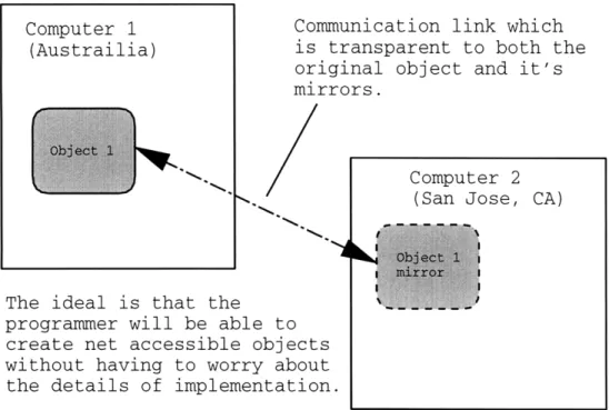
Figure 3-2: An illustration of the Mirror Paradigm.
hosted on a different computer that ideally provides a mirror copy of the original site, and with which a user can interact directly as if it were the original site. Why not provide the same type of service for individual objects rather than just entire web sites? The idea is this: Create a way to have an object instantiated on run machine, and then interact with it transparently on another machine just as if it was running locally. This turns out to be a powerful paradigm because it potentially (and ideally) allows the interaction with systems to be transparent to where the system is actually running. For instance, if in a robotic system there was a JointController object instantiated to control a specific joint of the robot, a mirror of that object could be brought up on any computer in the world with network access, and allow the user (or program) to interact with that object as if it were running on the local computer. The user would be able to change controller gains, modify simulated time delays, etc. The changes made in the mirror would be reflected back to the original, and visa-versa.
Of course there is still the issue of arbitration of conflicting commands. In the last implementation, the trouble of deciding what access to allow or disallow became burdensome. How is this system any different from that one? The difference is