CRASH BEHAVIOR OF THREE DIMENSIONAL
THIN-WALLED STRUCTURES
UNDER COMBINED LOADING
byHeung-Soo Kim
B.S. Mechanical Design and Production Engineering, Seoul National University, 1994 M.S. Mechanical Design and Production Engineering, Seoul National University, 1996
Submitted to the Department of Ocean Engineering in Partial Fulfillment of the Requirement for the Degree of
Doctor of Philosophy in Applied Mechanics at the
MASSACHUSETTS INSTITUE OF TECHNOLOGY June 2001
@ Massachusetts Institute of Technology 2001. All rights ri
Author ...
IsUT HUSETTS INSTITUTE OF TECHNOLOGY JUL 11 ?001 LIBRARIES
BARKER
Heung-Soo Kim April 2001 Certified by .. 'Tomasz Wierzbicki Professor of Applied Mechanics Thesis Supervisor/
Accepted by ...
Henrik Schmidt Professor of Ocean Engineering Chairman, Department Committee on Graduate Studies
CRASH BEHAVIOR OF THREE DIMENSIONAL
THIN-WALLED STRUCTURES UNDER COMBINED LOADING
Heung-Soo Kim
Submitted to the Department of Ocean Engineering
in April 2001, in partial fulfillment of the requirement for the degree of Doctor of Philosophy in Applied Mechanics
ABSTRACT
For the weight efficient and crashworthy design of the structural body of a transportation system, a thorough understanding of crushing behavior of thin-walled structural members such as spot-welded sheet metal beams or extruded aluminum beams must be gained. In the present thesis, the complex crushing process of three-dimensional thin-walled structures subject to combined loading is solved analytically and numerically. Also, several new design concepts of strengthening "S" shaped frame with regard to weight efficiency and energy absorption are proposed.
The mechanics of biaxial bending collapse and the collapse under combined bending and compression of thin-walled prismatic member are formulated and initial and subsequent shrinking interaction curves between the loading components are constructed. All the analytical derivations show close correlations with the results of the accompanying finite element analysis. Based on these two complex crushing mechanisms, the analytical derivation of the crushing resistance of three-dimensional "S" shaped frame is presented.
Extensive study on the strengthening of the three-dimensional "S" shaped frame is performed with two types of internal reinforcing member, diagonally positioned sheet metal stiffener and ultralight metallic foam-filler. The optimization process involving varying the cross-sectional shape and the type of reinforcing member for both aluminum-extruded member and spot-welded hat-type cross-section member is developed. Using the analytical closed form expression of the crushing force of "S" shaped frame, the optimization process was performed based on Sequential Quadratic Programming. As a more realistic application, a front side rail and subframe structure of a mid size passenger car is analyzed. The combinational optimization process of "Design of Experiment" and "Response Surface Method" is carried out with the objective of weight minimization while maintaining the same or higher level of crash energy absorption. Both methods of internal reinforcement show high increase in the energy absorption and weight efficiency. The gain in terms of the specific energy absorption varies from 37% to 267% depending on the method. The proposed theoretical understanding and the design methodologies could be used as crash oriented early-stage component design tools.
Thesis Supervisor: Tomasz Wierzbicki Title : Professor of Applied Mechanics
Acknowledgements
First and foremost, I would like to express my deepest gratitude to my advisor, Professor Tomasz Wierzbicki. His guidance, encouragement, and inspiration throughout my studies were invaluable. Not only did I earn my doctoral degree from MIT, but I also obtained an example from him for how I should live my life. Furthermore, I would like to thank the members of my doctoral thesis committee, Professor Mary Boyce and Professor Nicholas Patrikalakis, for their comments and advice in completing this thesis. I am also indebted to Professor Frank McClintock for his valuable comments on my research.
I would like to express my gratitude to the Safety Optimization and Robustness Group at Ford Motor Company - especially Dr. Ren-Jye Yang and Mr. Cheng-Ho Tho - for their support and kindness during my time there as a summer intern and for their continued assistance in the optimization part of my work. Also, I greatly appreciate the financial support provided by the Joint MIT/Industry Consortium on the Ultralight Metal Body Project.
Many thanks are due to the members of the MIT Impact & Crashworthiness Laboratory. I have been very fortunate to work with such intelligent and cooperative members. In particular, I would like to thank Dr. Sigit Santosa, Dr. Weigang Chen, Dr. Mulalo Doyoyo, Dr. Osamu Muragishi, Mr. Yingbin Bao, and Mr. Dirk Mohr.
I am also indebted to my former group members in the Advanced Machine Element Design Laboratory at Seoul National University. I will never forget their willingness to assist with my research and constant encouragement. I would like to express thanks to my former advisor, Professor Dong-Chul Han, and the Structure Analysis Group -Professor Shin-You Kang, Dr. Shin-Hee Park, Mr. Hong-Wook Kim. My special gratitude goes to Mr. In-Hyuk Lee at ESI Korea for his kind teaching and help with my research.
I wish to thank my friends for their continuous encouragement and for providing refreshment throughout my studies at MIT. Special thanks are due to Dr.Shin-Suk Park, Mr. Peter U. Park, Mr. Andy S. Kim, and Mr. Hyun-Gyu Kim. I would like to express my deep gratitude for my dearest old friends, Mr. Jae-Hong Kim and Gaette, Mr. Jin-Wook Jung, Mr. Won-Shik Shinn, Mr. Jae-Won Song, and Mr. Jin-Young Jung.
Finally, and most importantly, I would like to express my warmest gratitude to my family, my father and mother, my brother and sister-in-law, and my sister and brother-in-law. I feel profoundly indebted to them for their continuous support, encouragement, and prayer.
Contents
1. Introduction ... 20
1.1 Research Objective and Scope ... 22
1.2 Thesis Structure ... 24
1.3 G eneral Form ulation ... 25
1.4 Dynamic Effect on the Crash Resistance ... 36
2. Biaxial Bending Collapse of Thin-walled Beams ... 39
2.1 Formulation of the Problem and Finite Element Modeling ... 40
2.2 Results : Moment - Rotation Angle ... 46
2.3 Development of Moment Interaction Curve ... 49
2.3.1 Initial Failure Locus ... 49
2.3.2 Shrinking of the Failure Locus and Normality Rule ... 56
2.3.3 Formulation of Generalized Interaction Curve with Softening .... 60
3. Crush Behavior of Thin-walled Prismatic Columns under Combined Bending and Compression ... 65
3.1 Formulation of the Problem and Finite Element Modeling ... 65
3.2 Results : Axial Force and Bending Moment Response ... 71
3.3 Construction of the First Failure Locus ... 76
3.4 Shrinking of Failure Locus ... 83
3.4.2 A nalytical R esults ... 86
4. Analysis of Crushing Response of S shaped Frame ... 93
4.1 One-hinge Pin-pin Supported Model ... 94
4.2 Planar S Shaped Frame ... 99
4.2.1 Peak F orce ... 100
4.2.2 Load-Deflection Relation ... 106
4.3 Three-Dimensional S Shaped Frame ... 110
4.3.1 Finite Element Modeling ... 110
4.3.2 Determination of the Bending Axis ... 112
4.3.3 Calculation of Crushing Force of Three-Dimensional S Frame ... 117
5. Strengthening of Three-Dimensional S Shaped Frame ... 119
5.1 Effect of the Cross-Sectional Shape on Crash Behavior of a Three Dimensional "S" Frame ... 122
5.1.1 Formulation of the Problem and Finite Element Modeling ... 122
5.1.2 R esults ... 125
5.1.2.1 Empty Column ... 125
5.1.2.2 Analytical Prediction ... 127
5.1.2.3 Effect of Different Reinforcing Member ... 128
5.1.2.4 Effect of Foam Strength ... 132
5.1.2.5 Partial Foam-Filling ... 135
5.1.2.6 New Design of Diaphragm Type 2 ... 136
5.1.2.7 Effect of Imperfection ... 139
5.1.3 D iscussion ... 144
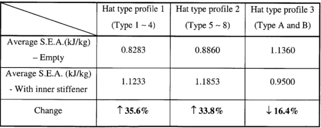
5.2 Effect of the Cross-sectional Shape of Hat-type Cross-sections on Crash Resistance of an "S"-frame ... 145
5.2.1 Formulation of the Problem and Finite Element Modeling ... 145
5.2 .2 R esults ... 149
5.2.2.1 Empty Model ... 149
5.2.2.2 Model with Inner Stiffening member ... 152
5.2.2.3 Specific Energy Absorption ... 156
5.2.2.4 Aluminum Foam-filled Model ... 158
5.2.2.5 Model with varying orientation of the inner stiffener ... 160
5.2.2.6 Effect of trigger and partial internal stiffener ... 163
5.2.2.7 Specific Energy Absorption ... 165
5.2.3 D iscussion ... 166
5.3 Optimization of the Aluminum Foam-filled Three Dimensional "S" Shaped F ram e ... 16 8 5.3.1 Optimization Formulation ... 168
5.3.2 Crash Reponses and Energy Absorptions of S-Frames ... 169
5.3.3 Solution Algorithm ... 172
5.3.4 C ase Study ... 173
5.4 Numerical Optimization of Aluminum Foam-filled Front Side Rail ... 176
5.4.1 Overview of the Model ... 178
5.4.3 Description of Foam-Filled Model ... 181
5.4.4 Numerical Optimization ... 183
5.4.5 Optimization Results ... 187
5.4.6 Weight Efficiency ... 191
6. Conclusions and Recommendations ... 194
6.1 C onclusions ... 194
6.2 Future R esearch ... 196
B ib liograp h y ... 197
A p p en d ix ... 205
List of Figures
1-1 Simplified crash pulse of a passenger car ... 23
1-2 Crash pulse of 1998 Nissan Altima [32] ... 23
1-3 Conceptual cut of the zone of plastic deformation ... 26
1-4 Cross-section deformation mode of the plastic hinge ... 28
1-5 Comparison of the components of moment ... 28
1-6 Energy equivalent flow stress ... 31
1-7 Bending about non-principal axis ... 32
1-8 The interaction curve between two normalized bending moment components ... 34
1-9 Stress distribution for combined bending and compression (fully plastic state),where Od is the position of neutral axis ... 34
1-10 Interaction curve between axial force and bending moment ... 35
2-1 Global coordinate system and the specimen subjected to biaxial bending ... 41
2-2 Relation between the components of the bending moment vector in the global coordinate system and local coordinate system ... 42
2-3 Constraint and loading conditions ... 43
2-4 Finite elem ent m esh ... 44
2-5 Stress-strain curve used for BS 1775 ERWi 1 steel ... 45
2-6 Resultant moment vs. rotation of a rectangular section 1 ... 47
2-7 Resultant moment vs. rotation of a rectangular section 2 ... 47
2-8 Resultant moment vs. rotation of a square section ... 47
2-10 Initial failure loci of Rectangle 1 ... 50
2-11 Initial failure loci of square section ... 50
2-12 Distribution of axial strain at the plastic hinge resulting from independently applied increm ental rotation ... 51
2-13 Distribution of total strain increment and tensile/compressive stresses over the beam
circum ference ... 51
2-14 Example of the first yield locus ... 52
2-15 Plots of the normalized failure locus predicted by Eq.(2-1 1) and obtained from FE
resu lts ... . ... 53
2-16 Two deformation modes in biaxial bending collapse ... 54
2-17 Critical orientation angle W, of analytical prediction and obtained from FE
calculation ... ... 55
2-18 Direction of increment of rotation versus loading ... 58
2-19 Derivation of trajectory from the interaction curve ... 59
2-20 Trajectory of top end node predicted analytically and FE simulation results .... 59
2-21 Distribution of axial strain at the plastic hinge resulting from independently applied incremental rotation in the post-buckling range ... 60
2-22 Distribution of total strain and stress over the circumference in the post-buckling ran g e ... 6 0
2-23 Determination of peak moment ... 63
2-24 Analytical prediction of uniaxial bending collapse, square section, t=0.7mm ... 63
2-25 Analytical prediction of failure locus in biaxial bending square section, t=0.7mm
... . . .. 6 4
2-26 Analytical prediction of failure locus in biaxial bending, with exact moment-rotation
characteristics in uniaxial bending ... 64
3-1 Configuration of the model ... 66
3-2 Displacement vector and the dimensionless yield locus ... 69
3-3 Relation between rate of translation and rotation ... 69
3-4 AA 6063 T7 stress-strain curve ... 71
3-5 Moment generated by the axial force ... 72
3-6 The effect of axial force to the bending moment ... 72
3-7 Translational velocity generated in pure bending (t=1.6) ... 73
3-8 D eform ed shapes ... 74
3-9 Axial force (b/t=50) ... 75
3-10 Bending moment (b/t=33.3) ... 75
3-11 Position of the neutral axis ... 76
3-12 Stress distribution in Case (a) ... 77
3-13 Stress distribution of Case (b) ... 79
3-14 Analytically constructed first failure locus ... 81
3-15 Initial failure locus (b/t = 50) ... 82
3-16 Initial failure locus (b/t = 33.3) ... 82
3-17 Norm of displacement vector ... 84
3-18 Shrinking of failure locus (b/t=50) ... 85
3-19 Shrinking of failure locus (b/t=33.3)... 85
3-20 Failure locus for circular dented tube by Wierzbicki and Suh [28] ... 86
3-22 Force-displacement behavior of spring ... 87
3-23 Deformation of springs ... 88
3-24 Possible cases for Shanley spring model ... 90
3-25 Comparison between analytical prediction and numerical results (b/t=50) ... 92
3-26 Comparison between analytical prediction and numerical results (b/t=33.3) .... 92
4-1 Idealized front end of a car ... 93
4-2 One-hinge pin-pin supported model ... 94
4-3 Free body diagram of the column ... 96
4-4 Division of a plastic hinge into two pairs of compression and bending ... 98
4-5 Comparison of Eq.(4-6),(4-7), and (4-17) ... 99
4-6 Planar S shaped frame with three plastic hinges ... 100
4-7 Elastic response of S shaped frame with the external force ... 100
4-8 Equilibrium of force and moment for each component of S frame ... 101
4-9 Change of the tip angle ... 102
4-10 Deformation of springs in Shanley spring model... 104
4-11 Peak spring force ... 105
4-12 Pairs of the compression and bending in the planar S shaped frame ... 107
4-13 Crushing force of S frame ... 109
4-14 Three dimensional S shaped frame ... 110
4-15 Finite element mesh of a three-dimensional S frame ... 111
4-16 Deformed shape of 3-D S frame (a/b = 1.0 : square cross-section) ... 111
4-17 Deformed shape of 3-D S frame (a/b = 1.3) ... 111
4-18 Deformed shape of 3-D S frame (a/b = 1.4) ... 111
4-19 Deformed shape of 3-D S frame (a/b = 2.0) ... 112
4-20 Orientation angle of bending axis ... 112
4-21 Normalized fully plastic bending moment ... 114
4-22 Front view of the deformation ... 115
4-23 Sectional collapse modes in three plastic hinges (a/b = 2.0) ... 116
4-24 Contribution of the torsion to the total magnitude of the sectional moment (alb = 2 .0 ) ... 116
4-25 Comparison of crushing force of square cross-section S frame : Analytical prediction vs FE results ... 118
4-26 Comparison of crushing force of rectangular cross-section S frame : Analytical prediction vs FE results ... 118
5-1 Cross-sectional collapse at the plastic hinge under uniaxial bending ... 119
5-2 Cross-sectional collapse at the plastic hinge under biaxial (diagonal) bending ... 119
5-3 Comparison of crushing resistance - constant M0 and decaying function of M(0) ... 1 19 5-4 Configuration of the model. All dimensions are in mm ... 123
5-5 L oading condition ... 123
5-6 Various cross-sectional shapes considered ... 124
5-7 Finite elem ent m odel ... 124
5-8 AA 6063 T7 stress-strain curve ... 125
5-9 Force response of empty member ... 126
5-10 Deformed shape of empty member ... 126
5-12 A construction paper model of square S-frame. The member can be completely
flattened out with bending deformation only without membrane tension ... 127
5-13 Various cross-sectional types ... 128
5-14 Sectional force response ... 129
5-15 E nergy absorbed ... 129
5-16 D eform ed shapes ... 130
5-17 Comparison of Specific Energy Absorption ... 131
5-18 Force response of foam-filled member ... 133
5-19 Energy absorbed by foam-filled member ... 133
5-20 Comparison of Specific Energy Absorption ... 134
5-21 Deformed shapes of foam-filled model ... 134
5-22 Partially foam-filled model ... 135
5-23 D eform ed shapes ... 135
5-24 Force response of partially foam-filled model ... 136
5-25 New design of diaphragm type 2 ... 137
5-26 Deformed shapes of new diaphragm type 2 ... 137
5-27 Comparison of force response for two types of diaphragm 2 ... 138
5-28 Comparison of energy absorbed for two types of diaphragm 2 ... 138
5-29 Im perfection type 1 ... 139
5-30 Im perfection type 2 ... 139
5-31 Deformed shapes at displacement = 150mm ... 140
5-32 Force response - Imperfection type 1 and imperfection type 2 ... 140 5-33 Deformed shapes of model with new diaphragm type 2 and imperfection type 1
... 14 1
5-34 Deformed shapes of model with new diaphragm type 2 and imperfection type 2
... 14 1
5-35 Force response ... 142
5-36 E nergy absorbed ... 143
5-37 Comparison of Specific Energy Absorption ... 143
5-38 Configuration of the model. ( all dimensions are in mm ) ... 146
5-39 Loading condition ... 146
5-40 Various cross-sectional shapes considered ... 147
5-41 Finite elem ent m odel ... 148
5-42 Stress-strain curve of the material used in this study ... 148
5-43 Force response of Type 1-4 ... 150
5-44 Force response of Type 5-8 and Type A, B ... 150
5-45 Energy absorbed by various cross-sections (refer to Fig.5-40) ... 151
5-46 Deformed shapes of the various empty models ... 152
5-47 Force response of Type 1-4 with inner stiffener ... 153
5-48 Force response of Type 5-8 and Type A and B with inner stiffener ... 153
5-49 Energy absorbed by various cross-section model with inner stiffener ... 154
5-50 Deformed shapes of various models with inner stiffener ... 155
5-51 Comparison of Specific Energy Absorption: Empty model ... 157
5-52 Comparison of Specific Energy Absorption: Model with inner stiffener ... 157
5-53 Force response of foam-filled model ... 159
5-55 Varying internal stiffener ... 160
5-56 Change of orientation angle c ... 161
5-57 S-frame with varying inner stiffener ... 161
5-58 Im perfection type 1 ... 161
5-59 Im perfection type 2 ... 161
5-60 Force response of the member with varying inner stiffener ... 162
5-61 Deformed shapes of the model with varying inner stiffener ... 162
5-62 Type 6 with new design of internal stiffener and trigger ... 163
5-63 Force response of the various cases of Type 6 model ... 164
5-64 Deformed shapes of various cases of Type 6 model ... 165
5-65 Specific energy absorption ... 166
5-66 A foam-filled square cross-section ... 171
5-67 The specific energy absorptions of optimized foam-filled and empty sections .. 175
5-68 General Procedure of the Crash Optimization ... 177
5-69 Front side rail and subassembly structure ... 178
5-70 Wall force response of original front rail structure ... 179
5-71 Deformed shape of original model with trigger ... 179
5-72 Elastic buckling mode shape of the cross-section ... 180
5-73 Front end parts for quasi-static crushing ... 180
5-74 Force response of crushing of front end parts ... 181
5-75 Aluminum foam-filled front side rail ... 182
5-76 Mechanical properties of aluminum foam (compression) ... 182
5-77 The approximate optimization process ... 187
5-78 Wall force response of Optimized aluminum foam-filled front side rail ... 191
5-79 Comparison of the specific energy absorption: original design vs foam-filled optim um designs ... 192
5-80 Relation between weight and energy absorbed ... 192
A-1 Case 1 : Both Compression ... 205
A-2 Case 2 :
fi
- Compression, f2 - tension, subcase 1 ... 206List of Tables
2-1 Geometry of the cross sections ... 43
5-1 Table.5-1 Properties of aluminum foam used ... 132
5-2 Summary of the Specific energy absorption ... 156
5-3 Optimum solutions for empty and foam-filled S-frames ... 174
5-4 Optimal LHS design matrix and FE results summary ... 185
5-5 Design variable and design space ... 188
5-6 Optimum Designs ... 188
5-7 Result summary for Optimum Design 1 ... 189
5-8 Result summary for Optimum Design 2 ... 189
5-9 Result summary for Optimum Design 3 ... 190
Nomenclature
Rate of external work
W . Rate of energy dissipation
f, Velocity vector
e Strain rate
H half-length of the local plastic fold
@k
rate of rotation vectorF external force
M moment
c-, yield stress
O energy equivalent flow stress
K curvature
Nap membrane force
Map bending moment of the shell
V volume
A area
No fully plastic sectional force
Mo fully plastic bending moment
N normalized sectional force
M normalized bending moment
W orientation angle of the cross-section in biaxial bending
Wcr critical orientation angle in biaxial bending
Mres resultant bending moment
Ms bending moment about strong principal axis
M, bending moment about weak principal axis
ms normalized bending moment about strong principal axis
mW normalized bending moment about weak principal axis
Q
first moment of inertia0 rotation in bending
M pre-buckling bending moment
M"' post-buckling bending moment
k norm of the displacement component
11 rate between rate of the rotation and the rate of transration
Mp fully plastic bending moment per unit length
EI bending rigidity
beff effective width
SEA specific energy absorption
Chapter 1. Introduction
Responding to an increasing public awareness about safety of transportation systems such as cars, trucks, airplanes, trains and ships, the industry is putting crashworthiness as a high priority feature [1-5]. The body of a vehicle is considered crashworthy if it deforms under prescribed force and preserves sufficient survival space around the occupants to limit bodily injury during an accident [6]. Controlling the deceleration within the distance available requires controlling forces and moments, given the mass and other constraints of the rest of the structure. Weight efficient and crashworthy car body is composed of thin-walled prismatic members, such as spot-welded sheet metal beams or extruded aluminum beams. The application of the thin-walled prismatic members into the structure of vehicle has stimulated the study on plastic collapse behavior under large axial and bending deformations.
The crushing response of axially compressed box beams has been extensively studied in connection with the lumped mass-spring model which was a dominant tool to calculate the crash response of the automotive structure in 1970's and early 1980's. Efforts were made to model the major structural components which absorb most of crash energy with nonlinear springs. For this purpose, Ohkubo [7] developed a simplified expression for the mean crushing force of closed-hat section members and Masanori and Funahashi [8] presented a simple equations to calculate peak and mean crushing force of spot-welded box column with hat-type cross-section. Mahmood and Paluszny [9] investigated the contribution of buckling of each component column wall to the crushing resistance of whole box column. Meng et al [10] carried out an experimental study on the axial
crushing of square tubes made of PVC, aluminum and mild steel. Abramowicz and Jones developed an approximate theoretical prediction for the axial progressive crushing of square and circular columns in the series of their studies [11-15]. The first comprehensive analytical solution for axial crushing of thin-walled prismatic box columns was published by Wierzbicki and Abramowicz [16]. The subsequent publication of Abramowicz and Wierzbicki [17] extended this theory to the multi-coiner prismatic
members. A more recent work by Wierzbicki et al [18] showed a way to calculate local
distribution of stresses at a given cross-section of the column, subject to axial crushing.
Abramowicz [19] and Kecman [20] addressed the problem of a deep bending collapse of open and closed section, respectively. Both authors followed the so-called kinematic approach to plasticity, and the method involved a determination of a suitable folding mechanism with stationary and/or moving plastic hinges. Cimpoeru and Murray [21] presented empirical equations of the moment-rotation relation of a square thin-walled tube subject to bending collapse. Similar approach was taken by Kecman et al [22]
through the numerous bending crush tests of the simplified thin-walled single cell section members. Mahmood et al [23] developed so-called "strip" method to solve the bending strength and collapse mode of vehicle structural members. Wierzbicki et al [24] developed a much simpler closed-form solution for bending collapse by generating first a numerical solution using commercial finite element code ABAQUS, analyzing the stress and displacement fields.
Based on the results published to date, the crushing response of thin-walled member subject to either axial crushing or bending collapse can be well predicted analytically, but these results cannot be applied directly to the structure under combined compression and bending, or bending with two bending axes. In real world applications, many structural members of the transportation systems are subject to a combined loading, and do not collapse in a planar way. Several approaches were made to attack this subject by Civil Engineering literature [25,26,27], but they did not provide the comprehensive understanding of complex crushing mechanisms. The only well documented work on the interaction between bending and compression was published by Wierzbicki and Suh [28]. They carried out plastic analysis of tubular members subjected to local denting under combined loading for offshore applications and developed a simplified model of a circular tube and constructed a failure locus on a purely theoretical basis.
Development of simplified tools for crash calculations to predict the crash response without use of the finite element tool or experiments is the ultimate goal in the field of
crash mechanics. Drazetic et al [29] analyzed a planar "S" shaped frame using nonlinear
springs by dealing with axial compressive collapse and bending collapse separately. A similar approach was taken by Kim et al [30] to calculate the crash response of full scale automotive structure as well as the occupant behavior. Park [31] applied this method in the crash analysis of aluminum space frame car. However, the interacting behavior of the compression and bending or bending between two different axes was neglected in their studies. The present author was involved in these studies during his work at the Seoul National University in Korea before coming to MIT. Clearly, these early analyses without the interaction effects have overpredicted the resulting crash forces. However, because no tests were made the inaccuracies have not been detected. To develop a simplified tool for crashworthiness analysis of complex thin-walled structures, the analytical solution of the crushing resistance under combined loads must be derived. The design of weight efficient and crashworthy structure of vehicle will be far more difficult without understanding of the complex crushing behaviors under combined loading.
1.1 Research Objective and Scope
The main objective of the present thesis is to develop a theoretical basis for predicting the crushing resistance of three-dimensional thin-walled structures subjected to combined loading. Based on this theory, several new design concepts of strengthening three-dimensional S frame with regards to weight efficiency and energy absorption are proposed.
The theory is developed in three steps. First, the limiting cases of axial compression and planar bending are constructed analytically and numerically to serve as reference solution for more complicated loading cases. Then the numerical analyses using nonlinear finite element code PAM-CRASH are carried out to learn about a nature of the complex interaction between the components of generalized cross-sectional forces and moments. Next, simplified solutions for the interactions between biaxial bending, and axial force and bending moment are developed and compared to the exact numerical solutions. The
analytical expression of crushing resistance of three-dimensional "S" frame is derived on those theoretical bases. Methods of strengthening of the S frame are studied extensively. Various types of cross-section and new idea of reinforcing "S" shaped frame with diagonally positioned internal members as well as the ultralight metallic foam-filling are investigated. As a systematic way of the design of thin-walled frame structures, the application of numerical optimization process into the S frame and a front side rail structure of mid size passenger car is carried out. The optimized crashworthy design of each structure is determined with regards to weight efficiency and energy absorption. The generalized crash pulse of a passenger car subject to frontal collision is shown in Fig.1-1 and compared with the crash pulse of a real passenger car (Fig.1-2) [32].
Deceleration ,
G2 ---
---G 1 ..---L2
Time or Deformation
Fig. 1-1 Simplified crash pulse of a passenger car
&umpr Effec 7 ZEnrie apke, Igd
Elfectim Psk .cceetion & tkm ; ... ... . .J' U PU l e iJ .QU 0.0 010 . deio nir
U. DAD 0.020 U. 40 0. 60 O.AK M.OO 0.120 0.140 Time (s)
Fig. 1-2 Crash pulse of 1998 Nissan Altima [32]
Mahmood and Aouadi[32] and Motsumoto et al [33] studied the relation between the injury level of occupants and the shape of the crash pulse. It was shown that to lower the injury level, GI should be increased and G2 lowered. Also, increasing GI yields lowering G2. The front side rail plays the most important role in L2 range. Considering the three-dimensional "S" shaped frame can be regarded as an idealized front side rail structure, the scope of this thesis will be focused on L2 region. However, as the G1 and G2 levels are related to each other, the results of the current study cover the overall characteristics of the crash pulse.
1.2 Thesis Structure
The mechanics of bi-axial bending collapse will be revealed in Chapter 2. The computational model used in this study follows the test program conducted by Brown and Tidbury [34]. Prismatic thin-walled beams with square and rectangular cross-section are subjected to bending collapse about two different axes. Two different loading conditions are used :
1) Prescribed axis of bending deformation 2) Prescribed axis of bending moment
The physical tests are replicated using nonlinear finite element method. Based on the careful observations of the finite element analysis results, the analytical expressions for the first and subsequent failure locus are developed. The collapse mode and the normality rule in plasticity will also be analyzed.
In Chapter 3 the initial and subsequent failure locus in combined bending and compression is generated numerically. This is followed by analytical derivation. A square cross-section beam with two different aspect ratios is chosen as a representative structure. The beam is subject to combined bending and compression by changing the ratio between the rate of prescribed translational displacement and rotational displacement. The first failure locus is derived analytically considering the stress distribution over the
cross-section, which depends on the position of the neutral axis. The subsequent shrinking of failure locus, which is expected as the deformation progresses, is constructed analytically using the concept of "Superbeam Element" and Shanley Spring model [35,36]. All the analytically predicted failure loci are compared with the results of finite element analysis.
The analytical derivation of the crushing resistance of three-dimensional "S" shaped frame is presented in Chapter 4 on the basis of the results developed in the previous two chapters. The model used in this chapter can be considered as the simplified front side rail commonly used in the automotive structure. The computational model is developed in three stages with increasing levels of complexity: A simple one-hinge pin-pin supported prismatic thin-walled column with square cross-section, planar "S" shaped frame, and finally three dimensional "S" shaped frame. In each case the finite element analysis is carried out to verify the analytical prediction of the crushing response.
The problem of weight efficient and crashworthy design of thin-walled structures under complex loading situation is formulated and solved in Chapter 5. The structure considered is the same three-dimensional "S" shaped frame. An extensive study on strengthening of the structure is performed. Two types of internal reinforcing member are introduced : 1) diagonally positioned sheet metal stiffener and 2) ultralight metallic foam-filler. The optimization process involves varying the cross-sectional shape and the type of reinforcing member for both aluminum extruded member and spot-welded hat-type cross-section member. Using the analytical expression of the crushing force of S frame, the optimization process based on "Sequential Quadratic Programming" (SQP) is carried out. As a more realistic application, a front side rail and subassembly structure of a mid size passenger car is analyzed, and the combinational optimization process of "Design of Experiment" (DOE) and "Response Surface Method" (RSM) is carried out with the objective of weight minimization while maintaining the same or higher level of crash energy absorption.
Finally, a summary of the new results is presented and discussed in Chapter 6. Recommendations for future studies are given.
1.3 General Formulation
The general expression of the equilibrium of a single structural element can be given in the form of the global balance between the rate of energy dissipation and the rate of external work[37].
where Wex, is the rate of external work, and *in is the instantaneous rate of energy dissipated at the plastically deforming region. u is the velocity vector and t is the strain rate resulting from
n.
It has been observed experimentally [11,13,20] that the plastic collapse or large shape distortion of prismatic members is localized over relatively narrow zones while the remainder of the structure undergoes a rigid body motion or elastic deformations. The assumption of a localized zone of plastic deformation enables one to describe the mechanics of the crushing process at the local level, which is used throughout in this thesis.X2
M2 X1
P
Fd
Fig. 1-3 Conceptual cut of the zone of plastic deformation
An illustration of a conceptual cut which contains the zone of plastic deformation is shown in Fig. 1-3. Consider a section of a prismatic member of length 2H, where H is the half-length of the local plastic fold. Inside of the two cuts, the arbitrary large
zone. The relative rates of translation and rotation vectors of the rigid part are noted as u0 and yY0, respectively. Thus, the rate of work done by the external force F and moment
M is expressed as,
Wext = F60 + M @0 (1-2)
Or in the expanded form
Wext = F1 1i + F2 2 +F3d3 +Mif +M2Vf2 +M3V3 (1-3)
The coordinate system used is shown as attached to a centroid of the conceptual cut. Shown in Fig.1-4 is the cross-sectional deformation mode of a center cut through the "plastic hinge" of the 3-D "S" shaped member. At the same time the relative transverse displacement and rotations of the end sections of the plastic hinge are vanishingly small, so that the deformation producing shear is very small.
0 =0 = 0 (1-4)
u2
3a
=At the same time the reaction shear forces F1 and F2 are non-zero from equilibrium. However, the shear work is small and will be neglected in the present study [38,39].
The plot of three components of the bending moment (M1, M2, and M3) taken from the
clamped end of 3-D "S" shaped member with square cross-section is given in Fig.1-5. These are the results of finite element analysis using PAM-CRASH. The magnitude of twisting moment (M1) is negligible compared to other moment components, thus
MI =0 (1-5)
Also, there is a negligible relative rotation on both sides if the plastic hinge.
VI = 0 (1-6)
Therefore, the contribution to the work from the shear and twisting moment are neglected.
Fig. 1-4 Cross-section deformation mode of the plastic hinge E E 0 2000 1500 1000 500 0 -500 -1000 -1500 -2000 0 50 100 150 200
Displacement of moving end (mm)
Fig. 1-5 Comparison of the components of moment
F2 0 = F30 = M Ifl = 0
Consequently, the components of the velocity vector considered in this study are
t0 = ao, 0, 0
(1-7)
(1-8)
0" = to, o2", #
1
(1-9)Accordingly, vectors of generalized loading should have the following non-vanishing components. F ={F, F2, F3} (1-10) - M (Twisiting moment) -- --- M2 (Bending moment) .--- M3 (Bending moment) --- ---- -. -. -. -. -. -. -. -. -. -. -. -. -. -. -. -. -. -. -. -. -. -. . ...
M =
{0,M
2,M3}
where F1 = F is the axial force and M2 and M3 are magnitudes of bending moment about two orthogonal cross-sections.
The rate of external work is expressed as follow.
Wet = Fa0 + M2V2 + M 3V3' +J p vidS (1-12)
where the last term on the right-hand side of Eq.(1-12) includes both distributed and concentrated transverse loads and v is the transverse velocity, i.e. ii = I 2 or W = 3
-Assuming that the rate of displacement is constant over the cross-section '= 8, the last term on the right-hand side of Eq.(1-12) becomes,
Js
pwdS = P$ (1-13)where P is the total lateral load acting on the transverse velocity 8.
With these assumptions, the final formula for the rate of external work is
S=Fa
+M 2 2/4 +MAO + PS (1-14)The rate of internal energy dissipation for a general shell of volume V is defined as
Eq.(1-15).
Wint =afl taIdV =
I
Ji oatagdA dL (1-15) The components of the stress tensor are related by the yield condition. The Von-Mises yield condition in plane stress takes the form [40]O(U" a ai Ca/
2
1 e a -2|= 0
2
where t is the uniaxial yield stress.
The strain rate tl. is obtained from the associated flow rule
29
(1-16) (1-11)
tafl
=, ao
au-
a (1-17)Using Love-Kirhihoff's hypothesis,
' # = '6" + zka) (1-18)
where z is the local through-thickness coordinate.
The rate of energy dissipation per unit area is expressed as,
Wnt per unit area = ta
r
O'a-dz + ka8 f,O-a
zdz=ta/Na +ka Ma
(1-19)
where membrane force NO and bending moment MOg are defined as,
Na =
j
adz/MaI = 6Aaa/zdz
(1-20)
(1-21) Considerable simplifications can be obtained for prismatic beams for which the only stress component is the direct stress a-= ai with the Euler-Bernoulli assumption for a beam E = g0 + K2X2+ K3X3 and dV = Adx (1-22) (1-23) Eq.(1-15) for the rate of internal work can be transformed to
2H 2H 2H
'it = JF tdx + JM2k 2dx + JM ksdx1
0 0 0
where
F = Jho-d' (1-25) r
M2 = Jhox2d' (1-26)
r
M3 = Jh-x3dF (1-27)
Assuming that the generalized forces are approximately constant within the plastic hinge, the integration with respect to xi can be easily performed to give
W* = Fai +M2 2 + M3 3 (1-28)
which is a special case of Eq.(1-2).
In this thesis the material is considered to be rigid-perfectly plastic with the flow stress ao defined as an average stress over a given strain range (0, Ef), following the theory by Abramowicz and Wierzbicki [17].
o = -(e)d (1-29)
This is illustrated in Fig.1-6, which shows the equivalence of the product GOFa to the actual value of the dissipated energy. Consequently, ao given by Eq.(1-29) is referred to as an energy equivalent flow stress and used as a nominal value of the stress in the plastic range in rigid perfectly plastic shells.
e f Fig. 1-6 Energy equivalent flow stress
Interaction curves for solid cross-sections
When a solid prismatic member with rectangular cross-section is subjected to the bending about non-principal axis, the general configuration is given in Fig. 1-7. This is a textbook problem both in the elastic and plastic range [41,42]. However, a simple derivation is presented here as an illustration with more complex cases of thin-walled members.
Zero stress axis
b M zb -a 0X 70 b a a
Fig.1-7 Bending about non-principal axis
From the figure the axis of the applied bending moment M makes an angle 0 with O ,while the zero-stress axis for full plasticity is assumed to make an angle cc with the principal axis O, where, from the figure,
b
tan a = - z (1-30)
a
By taking moments about O and Oy, the components M and My of the bending moment M are given by
MX = M cosO = 2ab2ao(1_ 1- z2 (1-31)
Note that these expressions hold for -1 z 5 1, that is, for the value of tan cc less than
b/a. Normalizing M, and My with the fully plastic bending moment about O (M,o, =
2ab 2), M - 1 - z2 (1-33) M 3 M 2~~ M - MY - az (1-34) M 3 By eliminating parameter z, m, =1- 3b M2 (1-35)
For the square cross-section member,
M = 3 4Y-M2 (1-36)
Similarly, for I z|> ,
mY = 3( -{j2
M (1-37)
For the square cross-section member,
32
mY =1 m2 (1-38)
4
The interaction curve between two bending moments components for solid square cross-section member of Eq.(1-36) and (1-38) are plotted in Fig.1-8. The normal at the point P is shown. The slope of the normal at P is -dmx/dmy, and from Eq.30), 33) and (1-34), this slope is tan a. Thus the normal at P forms an angle a with the direction of the axis mx. The normality rule is clearly satisfied in this case. Also note that in the above derivation the cross-section is constant and equal to the original cross-section. The case of collapsing section is treated in the next chapter.
-1 iI
SI -11
III
x
Fig. 1-8 The interaction curve between two normalized bending moment components
As a second example consider the solid prismatic member subjected to the combined bending and compression. The fully plastic stress distribution is illustrated as in Fig.1-9.
b GO d 2a. Pd d
Fig. 1-9 Stress distribution for combined bending and compression (fully plastic state) ,where Pd is the position of neutral axis
Then the axial force N and bending moment M are calculated as,
N = 2fibdo- = 3N0, M =bd (1-39) (1-40) y 1
where N and M, are fully plastic axial force and bending moment, respectively, defined by No = 2bdo MO =bd2 O (1-41) (1-42) By normalizing N and M N n = N No (1-43) (1-44) M m=1-fl 2
Eliminating the parameter 0 between the above equations, the normalized axial force and bending moment are simply related by,
m+n2
=1 (1-45)
Eq.(1-45) is plotted in Fig.1-10.
N/N
0
-1 0
Fig. 1-10 Interaction curve between axial force and bending moment
35
The initial yield locus in the form of the interaction curve between the loading components for solid cross-section is derived using classical plastic theory. In this thesis, this approach is generalized for the thin-walled structures. Furthermore, the analysis will be carried out up to deep collapse range, and this will place a solid basis for the derivation of complex crushing behavior of a three dimensional structure.
1.4 Dynamic Effect on the Crash Resistance
A dynamic collapsing process in the thin-walled structures involves many interacting effects which are not present in static collapse [43,44,83]. There are two most important factors identified in dynamic collapse under the impact velocity in the most of crash accidents where the strain rates are below 102 sec-. The first is the strain rate effect which is a material property whereby the yield or flow stress is raised. The second factor is the inertia effect developed within the structure by the rapid accelerations during the collapse
[45].
While the inertia effects were shown to be responsible for peak magnitudes of the instantaneous resisting forces and therefore do not contribute the crash energy dissipation, many studies have been conducted on the strain rate effect empirically or analytically yielding the simple equations relating the dynamic crash resistance and the static crush resistance. Ohkubo et al [7] suggested an empirical formula for dynamic load factor in closed-hat axially compressed columns. By fitting experimental data a ratio of dynamic to static crushing force was approximated by a straight line,
1d
=+0.0668Vo (1-46)
PS
where Pd is the dynamic crash force, P, is the static crushing force, and Vo is the initial
impact velocity. A different empirical formula was obtained by Wimmer [46] for square mild steel columns,
L= 1+ 0.07 V0082 (-47) PS
The Cowper-Symons equation [47] is used widely to relate the dynamic flow stress (o) to the static flow stress (a-).
d (N1Iq
"d =I+ -- (1-48)
a- D)
0
where t is the strain rate and D and q are material constants to be determined from the dynamic tensile tests on the material.
Based on the strain rate sensitivity on the yield stress of material, Masanori and Funahashi [8] derived the following equation for mild steel structure by simply applying the Cowper-Symonds equation with one-dimensional uniform deformation assumption.
Pd +245 04L0.2 (1-49) P, 2.475 x10~4L where L is the crushing distance.
Wierzbicki and Akerstr6m [48] derived the following equation with the consideration of complex folding mechanism of axially compressed mild steel box column.
d =1+0.11V0 7 14 " (1-50)
P,
Most recently Jones [15] suggested the following equations of mean dynamic crushing forces for top-hat (Eq. 1-51) and double-hat (Eq. 1-52) section members.
Pd =32.89M,(p/t)1/3 .3 (1-51)
Pmd = 52.20M,(P It) 1 ( 6+
jf")}(1-52)
where p is the total width of the cross-section, t is the thickness, D and q are the constants in Cowper-Symonds equation, and Mp is the fully plastic bending moment per unit length.
For impact velocities used in crash barrier tests the dynamic correction factor is in the range of Pd/Ps = 1.2-1.4. This of course applies to unitized steel body structures. Aluminum alloy have no or very little strain rate sensitivity. For all practical purposes no dynamic correction factor has to be introduced in all aluminum car bodies.
It was observed from the comparison of static and dynamic tests of crushing of thin-walled structures that the deformation patterns of sheet metal components differ little between static and dynamic loading conditions [48]. Thus the analytical derivations mostly on the static loading conditions obtained in this thesis could be easily applied to the actual crash calculation for practical purpose. However, the elevation of the crushing resistance in the dynamic cases should be considered using the equations given above.
Chapter 2. Biaxial Bending Collapse of Thin-walled Beams
Biaxial bending is defined as the bending about the non-principal axis. For example, a rectangular section beam bent along the diagonal line of the cross-section is considered to be subject to biaxial bending. Biaxial bending of cold-formed profiles has been studied in the Civil Engineering literature with regards to stiffness, buckling, and ultimate strength (Razzaq and William [25], Zhou and Chen [26], Liew and et al [27]).
Todorovska-Azievska and Kecman [49] carried out the theoretical and experimental analysis of the multi-axial collapse modes in rectangular section tubes, and showed that multi-axial hinge collapse characteristics can be derived from the uniaxial (bending and/or torsion) moment - rotation curves. The only well documented experimental study on this topic known to the author was reported by Brown and Tidbury [34].
The most important result of this chapter is a construction of the interaction curve between two principal bending moments. Brown and Tidbury distinguished between two cases of loading : 1) prescribed plane of bending and 2) prescribed direction of moment applications. Tests were run on mild steel prismatic beams with a square and rectangular cross-section. The empirically determined failure locus will be used to validate a part of our own numerical and analytical solutions. Brown and Tidbury tests were arranged to measure only the resistance of the beam near the peak moment.
The "uniaxial" bending collapse of thin-walled structures was studied by several authors [19-24]. A comprehensive analytical study of a deep bending collapse of thin-walled beam was reported by Wierzbicki et al [24]. The approach taken was to generate first a numerical solution (ABAQUS code was used), then analyze the stress and displacement fields and on that basis develop a much simpler closed-form solution.
A similar strategy was adopted in the present paper. Here the nonlinear computer program PAM-CRASH is used as a convenient tool to study a complex response of thin-walled square and rectangular beams subjected to a biaxial cantilever bending. A number of important questions were asked in the study.
* What is the peak load under the action of two mutually orthogonal bending moments?
* How the yield locus shrinks with hinge rotation?
* What is the effect of the aspect ratio and loading conditions on the evolution of the yield surface?
* How well the 'normality' rule is preserved in this problem with structural softening?
* How the folding mode in the hinge depends on the orientation of the bending moment application with respect to the principal inertia axes?
The performed numerical simulation (94 computer runs 14 hours each) gave an exhaustive answer to all of the above questions. Based on the general formulations described in the previous chapter, simple formulas were derived and closely followed numerical results.
2.1 Formulation of the Problem and Finite Element Modeling
Consider a thin-walled beam with a rectangular cross-section axbxt where a and b are widths of two sides and t is the wall thickness. The length of the beam is denoted by 1,
Fig.2-1. The bottom end of the beam is fully clamped, (for example encastred in a concrete foundation, Kecman [20]). The top end is laterally displaced and the vertical displacement is unrestricted. In this formulation the axial force is zero. Of interest in this study is the resisting force P and the resulting bending moments described by the components of the bending moment vector Mi, i=1,2,3.
Two rectangular Cartesian coordinate systems were introduced in the analysis. One is the global, laboratory coordinate system (x, y, z) in which the load is always applied parallel to the x-axis. The other is a local coordinate system (s, w, z) aligned with the principal moment of inertia axes of the cross-section. Referring to the moments of inertia I, and I,
the subscripts 's' means the 'strong' direction and 'w' the 'weak' direction. In general the above coordinate systems are rotated with respect to one another by the angle W about the column z axis, Fig.2-2. In the present paper V was a parameter of the orientation which was constant in each experiment and was varied in the range of 0 <W 90 in increments of 150. The components of the bending moments in the two coordinate systems are
related by the linear transformation
[M,] cosY sin1f] M 1
MW --siny cosqfMy I (2-1)
where the twisting moment M3= M, is the same in both systems.
Load z a t 1 y
Fig.2-1 Global coordinate system and the specimen subjected to biaxial bending
In order to compare the present numerical calculation with the available experimental results, the beam was loaded in the same way as in the Brown and Tidbury [34] tests. Thus, two types of loading conditions were considered:
Loading case 1 : Prescribed plane of bending
Loading case 2 : Prescribed direction of loading, no constraints on the beam deformations
41
y
I I I - X SM
In both cases the velocity boundary conditions were applied. The center of the top cross-section was pulled in the global x-direction causing the member to collapse with a generalized plastic hinge formed at the root of the cantilever beam.
Mres
-My Y
MX
-- WMes
(a) Loading case 1
X CC=J Mres Y - x ~' ~44 (b) Loading case 2
Fig.2-2 Relation between the components of the bending moment vector in the global coordinate system and local coordinate system
Loading case 1
In the Brown and Tidbury [34] experiments the test member HB, oriented at the desired axis angle V was constrained by two side stays (DB and BG) connected between the cantilever tip B, and spherical anchor-joints at D and G (refer to Fig.2-3 (a)). The anchors were arranged to the line on the horizontal straight line DHG passing through the encastered base H of the test piece. Hence, the axis of hinge rotation was constrained parallel to the global y direction. In the finite element modeling, the displacement u, of the top cross section was constrained to represent the experimental condition explained above. The bottom of the beam was clamped. In the above loading configuration the
Y
Y
reaction force develops in the side stays and the resulting bending moment vector Mres
forms an angle o to the x axis which is different from W. (see Fig.2-2 (a))
Loading case 2
The constraint imposed on the top cross-section was removed. The load was applied in the global x direction. Hence, the axis of moment exerted on the member was constrained as global y direction. Consequently cc=i. This situation is explained in Fig.2-2(b).
Three different cross-sections were selected for the analysis. The specifications are given in Table 2-1. The rectangular section 1 and a square section are chosen to compare the results with those by Brown and Tidbury. In addition, the rectangular section 2 with
45x30 (mm) was also considered. The aspect ratio (a/b) of rectangular section ranging
from 1:1 to 2:1 covers most of profiles encountered in practical applications. Two different thickness were considered for each case.
Table 2-1. Geometry of the cross sections
I a b thickness alb [mm] [mm] [mm] [mm] Rectangular section 1 306 51 25.4 1.2, 0.7 2 Rectangular section 2 270 45 30 1.2, 0.7 1.5 Square section 228 38 38 1.2, 0.7 1 z y Load B W B Y Load
(a) Loading case 1 (b) Loading case 2
Fig.2-3 Constraint and loading conditions
The geometrical model was established using the mesh generator program HYPERMESH. The finite element model was then completed with the pre-processor PAM-GENERIS. Actual calculations were performed on a SILICON GRAPHICS 02 workstation with
R-10000 processor using the explicit finite element code PAM-CRASH. The post-processor PAM-VIEW was used for visualization.
Following Wierzbicki et al [24], the width of the expected bending hinge (the folding wavelength 2H) can be calculated from
2H =.3V (2-2)
where c = (a+b)/2 for a rectangular section. Using the values from Table 1, the width of
the hinge was predicted to be equal to 2H = 30mm. The length of the beam segment with a finer mesh l should be larger than 2H. In the present analysis the localized length was taken as 1, = 40mm. Outside the localized plastic hinge the beam is deforming elastically. A coarse mesh with 5-8 elements per side is sufficient. The mesh density is doubled in the localized area.
(a) Rectangle 1 (b) Rectangle 2
Fig.2-4 Finite element mesh
![Fig. 1-2 Crash pulse of 1998 Nissan Altima [32]](https://thumb-eu.123doks.com/thumbv2/123doknet/14512484.529913/23.918.226.612.489.695/fig-crash-pulse-nissan-altima.webp)