Publisher’s version / Version de l'éditeur:
Polymer (United Kingdom), 55, 6, pp. 1317-1326, 2013-09-25
READ THESE TERMS AND CONDITIONS CAREFULLY BEFORE USING THIS WEBSITE.
https://nrc-publications.canada.ca/eng/copyright
Vous avez des questions? Nous pouvons vous aider. Pour communiquer directement avec un auteur, consultez la
première page de la revue dans laquelle son article a été publié afin de trouver ses coordonnées. Si vous n’arrivez pas à les repérer, communiquez avec nous à [email protected].
Questions? Contact the NRC Publications Archive team at
[email protected]. If you wish to email the authors directly, please see the first page of the publication for their contact information.
NRC Publications Archive
Archives des publications du CNRC
This publication could be one of several versions: author’s original, accepted manuscript or the publisher’s version. / La version de cette publication peut être l’une des suivantes : la version prépublication de l’auteur, la version acceptée du manuscrit ou la version de l’éditeur.
For the publisher’s version, please access the DOI link below./ Pour consulter la version de l’éditeur, utilisez le lien DOI ci-dessous.
https://doi.org/10.1016/j.polymer.2013.09.030
Access and use of this website and the material on it are subject to the Terms and Conditions set forth at Structural influence of hydrophobic diamine in sulfonated poly(sulfide sulfone imide) copolymers on medium temperature PEM fuel cell
Lee, Kang Hyuck; Lee, So Young; Shin, Dong Won; Wang, Chenyi; Ahn, Sang-Hyun; Lee, Kee-Jung; Guiver, Michael D.; Lee, Young Moo
https://publications-cnrc.canada.ca/fra/droits
L’accès à ce site Web et l’utilisation de son contenu sont assujettis aux conditions présentées dans le site LISEZ CES CONDITIONS ATTENTIVEMENT AVANT D’UTILISER CE SITE WEB.
NRC Publications Record / Notice d'Archives des publications de CNRC: https://nrc-publications.canada.ca/eng/view/object/?id=9bd4f3f5-99e0-4418-ac42-b10f7778d98c https://publications-cnrc.canada.ca/fra/voir/objet/?id=9bd4f3f5-99e0-4418-ac42-b10f7778d98c
1
Structural influence of hydrophobic diamine in sulfonated
1
poly(sulfide sulfone imide) copolymers on medium temperature PEM
2
fuel cell
3 4
Kang Hyuck Lee a, So Young Lee a, Dong Won Shin a, Chenyi Wang a, Sang-Hyun Ahn b, 5
Kee-Jung Lee b, Michael D. Guiver a,c and Young Moo Lee a,b,* 6
7
a
WCU Department of Energy Engineering, Hanyang University, Seoul, 133-791, Republic 8
of Korea 9
b
Department of Chemical Engineering, Hanyang University, Seoul, 133-791, Republic of 10
Korea 11
c
National Research Council, Ottawa, Ontario, K1A 0R6, Canada 12 13 14 15 16 17 18 19 20 *
Corresponding author: Young Moo Lee, Tel. +82-2-2220-0525, Fax. +82-2-2291-5982, 21 E-mail: [email protected] 22 23 24 25 Manuscript
2
Abstract
1
Sulfonated poly(sulfide sulfone imide) copolymers containing flexible sulfide bond and 2
six-membered imide ring were synthesized by random polycondensation. Two types of 3
membranes were prepared by using different non-sulfonated diamines to investigate the 4
effects of the hydrophobic component. IECw values were controlled to 1.51 1.94 meq.g-1
5
depending on the degree of sulfonation (DS) which was in the range of 50 to 80%. The 6
membrane series showed good thermal stability (Td 5%: > 310 oC) and mechanical properties
7
(tensile strength > 30 MPa). Dimensional stabilities of the membranes were excellent with 8
23 35% increases, even at 100 oC. Proton conductivities of two types of membranes 9
composed of different hydrophobic diamines display a relatively good correlation with water 10
content, morphology. In fuel cell tests, the S-PSI60 membrane shows relatively high current 11
density of 250 mA cm-2 at 0.6 V and maximum power density of 175 mW cm-2 at 120 oC, 12
35% RH, 1.5 atm. 13
14
Keywords: Medium temperature PEMFC, polymer electrolyte membrane, sulfonated
15
polyimide, poly(phenylene sufide sulfone imide), hydrophobic component 16 17 18 19 20 21 22 23
Introduction
243
Much attention has been paid to polymer electrolyte membrane fuel cells (PEMFC)s as 1
promising alternative power sources due to advantages such as high power density, high 2
efficiency and zero emission. Consequently, PEMFCs are being considered as potential 3
energy sources for stationary, automotive and mobile devices [1-4]. While perfluorosulfonic 4
acid ionomers (PFSA) like Nafion® have been widely used in practical fuel cell applications 5
in the past few decades due to their high proton conductivity, good mechanical strength and 6
chemical stability, they suffer from well-recognized drawbacks of high cost, low application 7
temperatures ( 100 oC) and high fuel permeability [5, 6]. 8
Recent research has focused on the development of PEMFCs that operate at medium high 9
temperature (100 200 oC) [7-12]. The medium high temperature PEMFCs offer several 10
advantages, such as reduced catalyst poisoning by CO, higher reaction efficiencies, more 11
effective heat management, high fuel diffusion rate and lower cost. However, the relatively 12
low glass transition temperature (Tg 111 oC for H+ form), susceptibility to dehydration and
13
conductivity loss of Nafion® limits operating it in the medium high temperature range [5, 14
13]. As replacements for ionomers, sulfonated hydrocarbon membranes, acid-doped 15
polybenzimidazole (PBI) membranes, inorganic additive composite membranes, pore-filling 16
reinforced membranes and blend membranes have been studied for medium high 17
temperature PEMFCs [9, 14, 15]. 18
Recently, sulfonated hydrocarbon membranes have been studied for medium temperature 19
applications (100 oC 120 oC), to overcome the performance degradation of PFSA 20
membranes and the concerns about acid leakage of acid-doped PBI membranes. Various 21
hydrocarbon membranes such as sulfonated polymers derived from poly(phenylene oxide), 22
poly(sulfone), poly(arylene ether sulfone), poly(phenylene sulfide sulfone), poly(ether ether 23
ketone), poly(arylene ether nitrile) and polyimide have been studied [7, 9, 10]. Common 24
4
characteristics of these polymers are good mechanical strength, thermal stability, chemical 1
resistance and low cost. However, these polymer membranes rely on water as a proton carrier, 2
so water uptake and retention properties are important issues. In addition, sufficient proton 3
conductivity and control of dimensional changes at medium temperature remain challenges. 4
As previously reported, aromatic sulfonated polyimide (SPI) membranes are promising 5
candidates for use in medium temperature PEMFC (MT-PEMFC) applications, because they 6
possess good thermal and mechanical properties, excellent dimensional stability, thermo-7
oxidative stability, and superior solvent resistance [16-20]. In particular, dimensional stability 8
is an essential property for MT-PEMFC [11]. However, SPI membranes have several 9
drawbacks, such as low hydrolytic stability. To overcome these drawbacks, several 10
approaches have been studied. One approach is to incorporate a crosslinkable amine 11
monomer like tris-amine into SPI membranes [21, 22], which showed better hydrolytic 12
stability after crosslinking. Another approach to enhance SPI membrane stability is by 13
introducing a flexible sulfonic acid side chain group to reduce hydrolysis of the main chain 14
[23]. In this case, the water surrounding sulfonic acid groups exists distant from the polymer 15
main chain. Thus, hydrolytic stability of the membranes is enhanced. Similar in concept to 16
the side chain type sulfonic acid groups is the introduction of spacer groups [24, 25]. The 17
existence of a spacer group within the main chain between sulfonic acid groups and imide 18
linkage improves resistance to imide hydrolysis. 19
In our previous study, sulfonated poly(phenylene sulfide sulfone nitrile) (SPSSN) was 20
synthesized [26-28]. The sulfide groups can be oxidized to sulfone groups during the PEM 21
operation by reaction with hydroxyl radicals. This change can improve the oxidative stability 22
and long term stability [26, 29-31]. Using this concept, we designed copolymers with sulfide 23
linkage and spacer groups. In order to compare morphological effects, two types of 24
copolymer structures were prepared from two different hydrophobic diamines, 4,4'-25
5
diaminodiphenyl sulfide (TDA) and 4,4'-bis(4-aminophenylthio)diphenylsulfone (BAPTPS). 1
In the present study, sulfonated poly(sulfide sulfone imide) copolymers containing flexible 2
sulfide linkages and six-membered imide rings were synthesized. The effects of membrane 3
morphology and polymer chain structure due to different hydrophobic monomers were 4
characterized. It is our goal to evaluate this copolymer membrane as polymer electrolyte 5
membranes for medium temperature (120 oC, 35% RH). 6 7 8 9 10 11 12 13 14 15 16 17 18 19 20 21 22
Experimental section
23 Materials 246
1,4,5,8-Naphthalenetetracarboxylic dianhydride (NTDA), 4,4'-diaminodiphenyl sulfide 1
(TDA), 4-aminothiophenol, 4,4'-dichlorodiphenyl sulfone (DCDPS), m-cresol, 1-methyl-2-2
pyrrolidinone (NMP), dimethyl sulfoxide (DMSO), dimethylacetamide (DMAc), isopropanol 3
(IPA), triethylamine (TEA), benzoic acid, toluene, and potassium carbonate were purchased 4
from Sigma Aldrich Co. 3,3'-Disulfonate-4,4'-dichlorodiphenyl sulfone (SDCDPS) was 5
synthesized by sulfonation of DCDPS with fuming sulfuric acid (30% free SO3, Sigma
6
Aldrich, WI, USA) as previously reported [32]. NTDA, SDCDPS and potassium carbonate 7
were dried at 120 oC in a vacuum oven for 24 h before use. Other reagents were used as 8
received. 9
4,4'-Bis(4-aminophenylthio)diphenylsulfone-3,3'-disulfonic acid (BAPTPSDS) as 10
hydrophilic sulfonated diamine and 4,4'-bis(4-aminophenylthio)diphenylsulfone (BAPTPS) 11
as hydrophobic diamine monomers were prepared by substitution reaction of 4-12
aminothiophenol with SDCDPS or DCDPS according to previous literature, respectively [33, 13
34]. 14
Synthesis of sulfonated polyimide copolymers
15
The synthetic procedure for the sulfonated poly(sulfide sulfone imide) copolymers was 16
similar to that of SPIs, as reported in previous studies [16-18, 22-24]. For convenience in this 17
study, the PSI refers to a copolymer composed of NTDA, BAPTPSDS and TDA, and S-18
PSFI refers to one composed of NTDA, BAPTPSDS and BAPTPS. The S-PSI50 is given as a 19
representative example, where 50 refers to DS. To a 100 mL three-neck flask equipped with a 20
mechanical stirrer, and a cooling condenser, 1.56 g (2.5 mmol) of BAPTPSDS and 15 mL of 21
m-cresol were added under nitrogen atmosphere. After adding 2.1 mL (15 mmol) of TEA, the 22
reaction mixture became clear due to the formation sulfonic acid TEA salt. Then, 0.54 g (2.5 23
mmol) of TDA, 1.56 g (5 mmol) of NTDA, 1.22 g (10 mmol) of benzoic acid and an 24
additional 15 mL of m-cresol were added, successively. The reaction mixture was heated to 25
7
80 oC for 6 h and 180 oC for 20 h and then cooled to room temperature. The viscous brown 1
mixture was precipitated into acetone. The resulting fiberlike precipitate was washed with 2
acetone several times. The obtained S-PSI50 copolymer was dried under vacuum at 80 oC for 3
24 h. S-PSI60 and 70 copolymers were prepared by controlling the DS by the monomer feed 4
ratio. S-PSFI60, 70 and 80 copolymers composed of BAPTPS were also obtained using the 5
same synthetic route. 6
Membrane preparation
7
The SPIs in their TEA salt form were dissolved in DMSO to 12 wt% concentration. The 8
polymer solutions were filtered with a 0.45 µm PTFE syringe filter. The two series of SPI 9
membranes were fabricated by casting the polymer solutions onto clean glass plates followed 10
by heating at 80 oC for 12 h, and dried in vacuum at 100 oC for 2 h, 120 oC for 2 h and 200 oC 11
for 2 h to remove solvent and anneal the membranes. The obtained membranes were acidified 12
in 1.0 N hydrochloric acid at room temperature for 2 days, then washed with deionized water 13
until the pH value was 7. The resulting proton form membranes were dried in vacuum at 100 14
o
C for 12 h. The thickness of the membranes were ~ 60 . 15
Measurements
16
The structure of SPIs was analyzed by 1H nuclear magnetic resonance spectra (NMR, 17
Mercury Plus 300 MHz, Varian, USA) with dimethyl sulfoxide-d6 (DMSO-d6) as a solvent.
18
The molecular weights of SPI series were measured by gel permeation chromatography (GPC, 19
Waters, MA, USA) with Styragel® columns and Waters 2414 refractive index detector with 20
NMP containing 0.05 M LiBr as an eluent. Molecular weights were calculated against 21
polymethylmethacrylate (PMMA) standard. 22
The thermal stability of the membranes was performed under nitrogen flow using 23
thermogravimetric analysis (TGA, Q500, TA Instrument, DE, USA). Thermogravimetric 24
experiments were carried out at a heating rate of 10 oC/min to 850 oC. Differential scanning 25
8
calorimetry (DSC, Q20, TA Instrument, DE, USA) was used for determining glass transition 1
temperature (Tg) and the thermal properties. The membranes density of proton form was
2
measured after they were dried completely. 2,2,4-Trimethylpentane (density = 0.692 gcm-3) 3
was used as the measurement solvent. The tensile strength and elongation of membranes were 4
measured using universal testing machine (Shimazu, AGS-500NJ, Tokyo, Japan) following 5
ASTM (ISO37-4). Dried and hydrated membranes were measured several times, and the 6
average value was taken. Under hydrated condition, samples were supplied with 7
humidification continuously. 8
Transmission electron microscopy (TEM) was used to investigate morphology of 9
membranes. The membranes were stained with lead ion (Pb 2+) by immersing in 0.5 M 10
lead(II) acetate aqueous solution, and rinsed several times with deionized water, and then 11
dried completely under vacuum. The stained samples were embedded in epoxy resin, 12
sectioned to 70 nm thickness with a RMCMTX Ultra microtome, and placed on copper grids. 13
TEM images were obtained using a Carl Zeiss LIBRA 120 energy-filtering transmission 14
electron microscope operating at an accelerating voltage of 120 kV. 15
The molecular structure of SPIs was simulated using the Material Studio program (Accelry, 16
San Diego, CA, USA) to confirm three-dimensional (3D) structures of the PSI and the S-17
PSFI copolymers. Molecular simulation was carried out using the COMPASS force field. 18
This method is suitable for estimation of polymer structure and conformational properties. 19
After constructing hydrophilic and hydrophobic repeating units, S-PSI and S-PSFI random 20
copolymers were built according to DS values and molecular weight. Energy minimization 21
was performed to eliminate any energy artifacts of the repeating units and polymer chain 22
matrix. 23
Oxidative stability and hydrolytic stability
24
The oxidative stability of membranes was determined by the following procedure. Small 25
9
pieces of membrane samples with weight of approximately 0.02 g were soaked in Fenton's 1
reagent (2 ppm FeSO4 in 3 wt% H2O2) at 80 oC for 1 h. The residual weight change of
2
samples was measured. In addition, the dissolution time at room temperature ( ) was 3
recorded when the membranes were dissolved completely. The hydrolytic stability was 4
evaluated by treating the membrane samples (1 4 cm) in water (100 oC) until their 5
mechanical properties were lost. The soaking time was recorded when each membrane was 6
broken by the bending on the both end sides of samples. 7
Water uptake, retention and dimensional stability
8
Water uptake (WU) and water retention were determined by measuring the weight of 9
proton form membranes before and after hydration. Before measurement, the membranes 10
were dried under vacuum at 120 oC for 12 h to measure the weight of dry membranes (Wdry).
11
For the weight of hydrated membranes (Wwet), the membranes were immersed in deionized
12
water for 24 h to reach equilibrium at given temperature (30 oC and 100 oC). Weight-based 13
water uptake (WUw) and volumetric water uptake (WUv) were calculated using the following
14
equations. Volumetric water uptake (WUv) was determined with density of water ( ) and
15
dried membranes ( ). 16
17
18
In addition, the water retention measurement was carried out in order to confirm the water 19
contents amount and desorption behavior [35, 36]. The fully hydrated samples at 100 oC were 20
maintained for 2 h at 100 oC under 35 % RH in the chamber and were weighed (Wwet, 2h).
21
Water retention was calculated by the following equation. 22
10
Dimensional stability of membranes was determined by measuring area (in-plane swelling) 1
and thickness (through-plane swelling) changes in the membranes at the same conditions of 2
water uptake. 3
4
5
Where Adry and Awet are the area of dried and wet membranes and ldry and lwet are the
6
thickness of dried and wet membranes, respectively. 7
Ion exchange capacity and proton conductivity
8
The weight-based ion exchange capacity (IECw) of membranes was determined by
acid-9
base titration. The proton form membrane samples were soaked in a 1.0 M NaCl solution for 10
24 h to exchange H+ ions with Na+ ions, and then released H+ ions were titrated by 0.01 M 11
NaOH solution using phenolphthalein as an indicator. Volumetric IEC values of dried 12
membranes (IECv(dry)) were calculated by multiplying the IECw and the membrane density.
13
The IEC values of hydrated membranes (IECv(wet)) were calculated based on measured water
14
uptake using the following equations. 15
16
17
The proton conductivity of each membrane sample (size: 1 cm × 4 cm) was characterized 18
at 80 oC under 100% RH, 100 oC under 85% RH, and 120 oC under 35% RH in a two-probe 19
type conductivity cell by using alternating current (AC) impedance spectrometer (Solartron 20
1260, Farnborough, Hampshire, UK). The temperature and RH were controlled by Fuel cell 21
station (CNL, Seoul, Korea) under nitrogen flow. Furthermore, the conductivity cell was back 22
pressurized at 1.5 atm to maintain hydrated status. All the membrane samples were measured 23
11
for in-plane and through-plane conductivity, respectively. The proton conductivity ( ) was 1
calculated from the following equation. 2
3
Where L is the distance between the counter electrodes and the working electrode, R is the 4
impedance of membrane and S is the cross-sectional surface area of membrane samples 5
(cm2). 6
MEA preparation and single cell performance
7
Membrane electrode assemblies (MEAs) were fabricated by a catalyst coated substrate 8
(CCS) method. Nafion® ionomer solution (20 wt% in IPA and water, DuPont, DE, USA) and 9
20 wt% Pt/C (Johnson Matthey Fuel Cell, London, UK) were mixed in water. The catalyst 10
slurry was coated on gas diffusion layers (GDLs) both anode and cathode sides until the 11
weight of Pt loading reached 0.5 mg cm-2. MEAs were fabricated by sandwiching the 12
membranes between the anode and cathode electrodes and hot pressed at 130 oC under a 13
pressure of 50 bar for 7 min. The prepared MEAs were tested in a single-cell fixture (with an 14
active area of 5 cm2). The PEMFC test was performed on test station (Won-A-Tech, 15
SMART1, Seoul, Korea). Electrochemical performances of S-PSI and S-PSFI series were 16
evaluated by following conditions. H2 and airwere fed at a flow rate of 100 mL min-1 at 80 oC
17
under 100% RH, 100 oC under 85% RH, and 120 oC under 35% RH respectively. In addition, 18
all operation conditions were back pressurized in the same way as conductivity measurements. 19
20 21
Results and discussion
22
Synthesis of monomers and copolymers
23
The synthetic procedure for sulfonated poly(sulfde sulfone imide) copolymers is shown in 24
12
Scheme 1. Two types of copolymers with various DS composed of hydrophobic diamine 1
monomers TDA or BAPTPS were synthesized in m-cresol with TEA as base and benzoic acid 2
as acid catalyst for carbonyl group in NTDA. Molar percentage of BAPTPSDS was targeted 3
as 50, 60 and 70 for S-PSI copolymer and 60, 70 and 80 for S-PSFI copolymer in order to 4
compare between S-PSI (containing TDA) and S-PSFI (containing BAPTPS) copolymers as 5
a function of similar IECw.
6
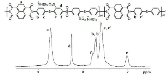
The structure of synthesized SPI copolymers series (TEA salt form) was confirmed by 1H 7
NMR spectroscopy, as shown in Figure 1. The aromatic proton signals of S-PSI and S-PSFI 8
copolymers were assigned. The signals corresponding to NTDA appeared at 8.75 ppm, and 9
the Hd, He and Hf signals were observed at 8.23, 7.02 and 7.78 ppm, respectively. The S-PSFI
10
copolymer showed two additional signals when compared with that of the S-PSI copolymer. 11
Signals at 7.43 ppm (Hg) and 7.92 ppm (Hh) were observed by influence of the sulfone group
12
in BAPTPS. 13
All the SPI copolymers were obtained as brown fiberlike solids. The high molecular 14
weights were measured by GPC and are shown in Table 1. The weight-average molecular 15
weights (Mw)of SPI copolymers were higher than 77 kDa, and the polydispersity indices
16
(PDI) were lower than 3. The SPI copolymer membranes were fabricated by solution casting 17
and were ultimately treated at 200 oC for 2 h for thermal annealing. In previous studies [27, 18
37, 38], it was observed that thermally annealed polymer electrolyte membranes showed 19
effective morphology for proton conduction and exhibited better electrochemical 20
performance and dimensional stability. 21
Thermal and mechanical properties
22
In the thermal stability tests of SPI membranes (proton form), the first degradation step 23
was observed at around 320 330 oC due to thermal degradation of sulfonic acid groups and 24
the polymer main chain decomposed at around 500 580 oC, as shown in Figure 2. All the 25
13
membranes exhibit good stabilities with high Td 5% (The 5 % weight loss temperature) in the
1
range of 313 320 oC. In addition, the Tgs of SPI membranes were investigated by DSC, and
2
the values were dependent on the DS. Note that the S-PSI membranes show higher Tg
3
(30 310 oC) than S-PSFI membranes (286 289 oC). 4
The mechanical properties of the S-PSI and S-PSFI membranes under dry and wet 5
conditions are summarized in Table 1. Under dry conditions, the S-PSFI membranes exhibit 6
higher maximum tensile strength than the S-PSI membranes, in the range of 42.2 56.8 MPa, 7
whereas the S-PSI membranes show slightly higher elongation at break than S-PSFI 8
membranes, in the range of 17 21 %. Under wet conditions, the elongation of S-PSFI 9
membranes was significantly increased, but the S-PSFI membranes exhibit lower tensile 10
strengths than the S-PSI membranes. Note that in both the dry and wet conditions, the two 11
different copolymer structures (S-PSI and S-PSFI), derived from the hydrophobic diamine 12
monomers TDA and BAPTPS respectively, affect the polymer chain matrix, morphology, and 13
ion clusters. Thus, the mechanical properties under dry and wet conditions display different 14
behavior. In summary, the S-PSI and S-PSFI series show good tensile strength but low 15
elongation when compared with Nafion® 212. 16
Oxidative stability and hydrolytic stability
17
The oxidative stability of the SPI PEMs was evaluated in Fenton’s reagent at 80 oC for 1 h 18
by measuring their weight changes after exposure. Fenton’s test provides an indication of 19
relative durability of PEM from free radical attack under fuel cell operating conditions [5]. 20
The dissolution times ( ) were also measured at 30 oC, and are listed in Table 1. All the 21
samples except S-PSFI80 showed a slight weight gain as a result of oxidation from S to 22
SO and SO2 [26, 29-31]. At the same time, membranes with high DS values
23
exhibited a faster degradation trend, as expected. Furthermore, the dissolution time ( ) of SPI 24
14
membranes occurred after more than 100 h, except for S-PSFI80. In general, the S-PSI series 1
were comparatively more stable in oxidative conditions than the S-PSFI series. 2
The stability of SPI membranes in water is one of the key issues, because the imide linkage 3
is relatively easy to hydrolyze at elevated temperature and humidity [39-41]. In previous 4
studies [24, 25, 33, 42], use of in-chain spacer groups between sulfonic acid groups and imide 5
linkages demonstrated improved stability in water. The six-membered imide ring has higher 6
hydrolytic stability than five-membered imide ring [39]. For these reasons, the copolymers 7
were designed with six-membered dianhydride (NTDA) and sulfonated diamine containing p-8
aminothiophenyl spacer groups (BAPTPSDS). The hydrolytic stabilities of S-PSI and S-PSFI 9
membranes were tested in water at 100 oC, and the time to membrane breakage when both 10
ends of samples were bent are listed in Table 1. The stability of membranes appeared to be 11
closely affected by DS and IEC values. The S-PSI70 and S-PSFI80 were broken after 53 h 12
and 48 h, respectively. However, the S-PSI50, 60 and the S-PSFI60, 70 exhibited relatively 13
good properties (87 112 h) compared to other SPI membranes [16, 19, 25]. 14
Membranes morphology and molecular simulation
15
In order to observe nano-phase separation of membranes, transmission electron 16
microscopy (TEM) images were taken as shown in Figure 3. Although both PSI and S-17
PSFI are random copolymers, well separated hydrophilic/hydrophobic morphology was 18
observed, unlike common random copolymers. The two types of membrane confirmed an 19
increasing trend of hydrophilic domain (dark area) with DS values. In particular, S-PSI60, 70 20
and S-PSFI70, 80 (IECw 1.73 meq cm-2) showed connected hydrophilic ionic clustered
21
morphology (S-PSI60 8 nm, S-PSI70 12 nm, S-PSFI70 13 nm and S-PSFI80 22
15 nm channel widths). Well-connected hydrophilic clusters with 8 nm size of the S-PSI60 23
should be helpful to have capillary water retention effect, as discussed in our previous 24
research [36]. S-PSI membranes showed more closely linked hydrophilic clusters compared 25
15
with S-PSFI membranes, despite having similar IECw values. The distance between formed
1
hydrophilic clusters in S-PSIs and S-PSFIs are 10 17 nm, 13 nm, respectively. 2
The three-dimensional (3D) polymer chain structures of the S-PSI60 and the S-PSFI70 3
copolymers were visualized by molecular simulation as shown in Figure 4. The hydrophobic 4
repeating unit of S-PSI (containing TDA) showed a torsional angle of 83o whereas the 5
repeating unit of S-PSFI (containing BAPTPS) showed a torsional angle of 23o. Chain length 6
of SPI series was controlled with number of repeating unit (RU , which corresponded 7
to minimum weight average molecular weight (Mw 70 kDa) of synthesized polymer, as
8
shown in Table 1. The S-PSI60 copolymer containing TDA as hydrophobic diamine showed a 9
comparatively ordered helical structure, whereas the S-PSFI70 copolymer exhibited slightly 10
entangled helical structure. These results might be influenced by differences of torsional 11
angle between S-PSI60 and S-PSFI70. Molecular simulation data was largely consistent with 12
the experimental data. A well-ordered helical structure could be helpful to facilitate dense 13
packing of hydrophilic domains, as identified in the TEM images. Thus the S-PSI60 14
membranes exhibited higher Tg, lower water uptake and better dimensional stability than
15
those of the S-PSFI70 membranes. 16
Water uptake, retention and dimensional stability
17
Water uptake and dimensional stability of PEMs are typically a function of IECw due to DS.
18
Water uptake and dimensional stability of sulfonated hydrocarbon membranes, when water is 19
primarily the proton carrier, are particularly important, unlike acid-doped PBI membranes 20
and ionic liquid composite electrolyte membranes. Furthermore, at medium temperature (100 21
o
C 120 oC) PEMFC operation conditions, water retention properties and good dimensional 22
stability of membranes are essential [7, 9, 14]. 23
Table 2 compares the density, IEC, water uptake and water retention of fabricated SPI 24
membranes. As expected, water uptake of both S-PSI and S-PSFI membranes increased with 25
16
temperature, IECw, and IECv(dry), due to the increased DS. All the membranes showed similar
1
water uptake behavior between weight% and volume% due to their density (1.45 1.48 g cm -2
3
). Also the volume-based IECv showed a very similar trend as the weight-based IECw. The
S-3
PSI70 and S-PSFI80 samples exhibited the highest water uptake in weight% and volume% 4
(40 wt% and 59 vol%) at 100 oC among all the samples. In general, the S-PSFI membrane 5
series exhibited higher water uptake than S-PSI. For example, with the same IECw of 1.73
6
meq cm-2, S-PSFI70 showed a larger water uptake (38 wt% and 55 vol%) than S-PSI60 (35 7
wt% and 52 vol%). In contrast to the water uptake, the S-PSI membranes showed superior 8
water retention than the S-PSFI membranes when compared to samples having similar IECw
9
values. Among them, the S-PSI60 retained about 5.3% after a water retention test, although 10
slightly lower than Nafion® 212 (5.7%). Considering these points, the S-PSI membranes have 11
more favorable morphology to retain water than the S-PSFI membranes at medium 12
temperature ( 100 oC) and low humidity operation conditions. 13
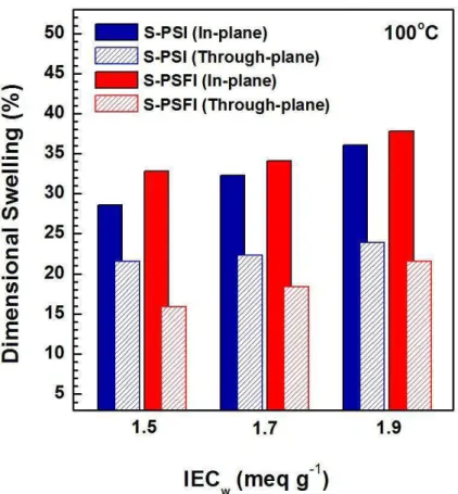
Figure 5 compares the IECw dependence of dimensional swelling ratio and relationship
14
between in-plane and through-plane changes at 100 oC for S-PSI and S-PSFI membranes. As 15
expected, the dimension of two types of PEM membranes was swelled by increasing IECw.
16
For all the samples, in-plane changes were larger than through-plane changes. However, the 17
PSI membranes exhibited a smaller gap between in-plane and through-plane than the S-18
PSFI membranes. Despite the S-PSFI membranes showing larger in-plane swelling, the 19
through-plane swelling of the S-PSI membranes was higher than the S-PSFI membranes. This 20
indicates that the S-PSI membranes have more efficient water channel in the through-plane 21
directions. In addition, all the fabricated SPI membranes achieved excellent dimensional 22
stability (in-plane: < 38% and through-plane: < 24%) in comparison with many sulfonated 23
hydrocarbon PEMs [14]. Accordingly, good dimensional stability of synthesized SPI 24
membranes could be obtained for medium temperature fuel cell operation. 25
17
Proton conductivity
1
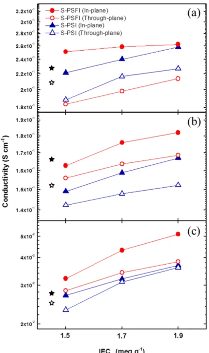
Proton conductivity is the most significant characteristic of fuel cell performance. Figure 6 2
shows the in-plane ( //) and through-plane ( ) conductivity of S-PSI and S-PSFI membranes
3
as a function of IECw at 80 oC under 100% RH, 100 oC under 85% RH and 120 oC under 35%
4
RH. For comparison, Nafion® 212 data are included as a reference. A conductivity cell fixture 5
was used to control temperature and hydration conditions by connecting into the fuel cell 6
stations. In addition, conductivity cell was back pressurized to 1.5 atm, and the relative 7
humidity (RH) was calculated and controlled by the temperature of the humidifier. N2 was
8
supplied at flow rate 0.1 mL min-1 in order to prevent any extraneous chemical reactions. 9
Proton conductivities decreased with increasing temperature above 80 oC. // of all the
10
membranes was higher than . The S-PSFI membrane series showed higher conductivity 11
than S-PSI membranes series. From these results, it is clear that the water uptake, IEC, and 12
proton conductivity are closely related. However, at 120 oC under 35% RH, the numerical 13
differences between the S-PSI and the S-PSFI series were reduced. In particular, different 14
polymer structure from hydrophobic diamines (TDA and BAPTPS) resulted in a decrease of 15
the conductivity gap between // and . Among them, the S-PSI60 and the S-PSI70
16
membranes exhibited isotropic conducting behavior at 120 oC under 35% RH. Furthermore, 17
the membranes with high IECw (1.7 and 1.9) were observed to have better proton
18
conductivity than Nafion® 212. The S-PSFI80 membrane showed the highest values ( //
19
0.051 S cm-1, 0.038 S cm-1) at 120 oC among all the samples. 20
Single cell performance
21
The achievement of superior performance of polymer electrolyte fuel cells is predicated on 22
a combination of PEM material properties such as high proton conductivity, appropriate 23
water uptake, good dimensional stability, mechanical properties, and chemical resistance [4, 24
43]. In particular, at medium temperature operation conditions, the role of dimensional 25
18
stability is essential [44]. As water is a proton carrier, moisture retention ability as well as the 1
amount of water uptake is also important. 2
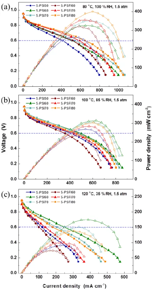
All single cells were assembled using the same methodology and electrode composition for 3
a fair comparison as reported before [45]. Figure 7 shows the current voltage polarization 4
curves of the S-PSI and the S-PSFI membranes, obtained at 80 oC, 100 oC and 120 oC, 5
respectively. In typical fuel cell operating conditions (80 oC, 100% RH, 1.5 atm), single cell 6
performance of all the membranes depends on proton conductivity, which is a function of 7
IEC and DS. The S-PSFI membranes were observed to have higher current density (520 8
649 mA cm-2) than the S-PSI membranes (415 540 mA cm-2) measured at 0.6 V. Note that 9
the morphology of the S-PSFI membranes is more efficient for proton transfer through the 10
membranes having high water uptake and relatively large ion clusters (13 20 nm). 11
However, when the operation temperature was increased to 100 oC and RH was reduced to 12
85 %, the tendency was quite reversed when comparing between the two PEM series having 13
similar IECw. For example, the S-PSI60 showed higher performance (current density (at 0.6
14
V) 498 mA cm-2 and maximum power density 314 mW cm-2) than that of S-PSFI70 15
(current density (at 0.6 V) 435 mA cm-2 and maximum power density 284 mW cm-2) 16
at 100 oC, 85% RH which is inverted from the results of 80 oC, 100% RH. 17
When the cell temperature and RH were changed from 100 oC and 85% RH to 120 oC and 18
35% RH, the difference was even more pronounced. Single cell performances of SPI 19
membranes series at 0.6 V were considerably decreased except S-PSI60. For example, current 20
density and maximum power density of the S-PSI70 decreased from 477 mA cm-2 and 305 21
mW cm-2 to 206 mA cm-2 and 151 mW cm-2, and also those of the S-PSFI80 decreased from 22
462 mA cm-2 and 303 mW cm-2 to 181 mA cm-2 and 138 mW cm-2, respectively. Interestingly, 23
in the case of S-PSI60, the extent of reduction of performance was comparatively low, and 24
achieved good cell performance at 120 oC under 35% RH (current density (at 0.6 V) 250 25
19
mA cm-2 and maximum power density 175 mW cm-2). These results indicate that a 1
moderate level of DS is one of the key factors and water moisture retention ability as well as 2
water uptake in membranes is considerably important. In particular, efficient morphology of 3
the membrane to allow proton transport and moisture retention capability due to narrow ion 4
clusters plays a significant role on the PEM performance at medium temperature, which is 5
probably controlled by different hydrophobic monomers. 6
7
Conclusions
8
A series of sulfonated poly(sulfide sulfone imide) copolymers (S-PSI and S-PSFI) were 9
successfully synthesized by facile polycondensation. All the membranes showed good 10
thermal stability and high mechanical strength as well as excellent dimensional stability of 11
membranes even at 100 oC. Two types of copolymer membranes composed of different 12
hydrophobic diamines (TDA and BAPTPS) displayed different morphology, evidenced by 13
TEM images and molecular dynamics simulation, due to polymer chain arrangement. This 14
correlated well with dimensional stability and mechanical properties. In particular, the 15
dimensional swelling ratio between in-plane and through-plane directions is closely related to 16
proton conductivity. In this regard, efficient ion clustered morphology in the through-plane 17
directions is controlled by polymer chain structure. In addition, to improve the fuel cell 18
performance, moderate IEC values as well as efficient morphology are essential. The amount 19
of water uptake is also important but the capacity to retain moisture is significant at medium 20
temperature (100 oC 120 oC). Considering fuel cell operation conditions, the S-PSI60 is a 21
promising candidate for MT-PEMFC due to its closely packed morphology and suitable 22
narrow conducting clusters (8 nm). In comparison with other sulfonated hydrocarbon 23
membranes, the S-PSI60 membrane achieved the expected cell performances at 120 oC under 24
20
35 % RH (current density (at 0.6 V) 250 mA cm-2 and maximum power density 175 1
mW cm-2 at 0.6 V), and showed the possibility of further applications. 2
3
Acknowledgements
4
This work was supported by the Joint Research Project funded by the Korea Research 5
Council of Fundamental Science & Technology (KRCF), Republic of Korea, as a part of the 6
“development and mechanism study of high performance and durable components for high-7
temperature PEMFCs” and Nano Material Technology Development Program through the 8
National Research Foundation of Korea (NRF) funded by the Ministry of Education, Science 9
and Technology. (2012M3A7B4049745). 10
11 12 13 14
21 1
References
2
1. Carrette L, Friedrich KA, and Stimming U. Fuel Cells 2001;1(1):5-39. 3
2. Hickner MA and Pivovar BS. Fuel Cells 2005;5(2):213-229. 4
3. Hickner MA, Ghassemi H, Kim YS, Einsla BR, and McGrath JE. Chemical Reviews 5
2004;104(10):4587-4612. 6
4. Zhang H and Shen PK. Chem Rev 2012;112(5):2780-2832. 7
5. Chen C, Levitin G, Hess DW, and Fuller TF. Journal of Power Sources 8
2007;169(2):288-295. 9
6. Sethuraman VA, Weidner JW, Haug AT, and Protsailo LV. Journal of The 10
Electrochemical Society 2008;155(2):B119-B124. 11
7. Li Q, He R, Jensen JO, and Bjerrum NJ. Chemistry of Materials 2003;15(26):4896-12
4915. 13
8. Einsla ML, Kim YS, Hawley M, Lee H-S, McGrath JE, Liu B, Guiver MD, and 14
Pivovar BS. Chemistry of Materials 2008;20(17):5636-5642. 15
9. Bose S, Kuila T, Nguyen TXH, Kim NH, Lau K-t, and Lee JH. Progress in Polymer 16
Science 2011;36(6):813-843. 17
10. Shao Y, Yin G, Wang Z, and Gao Y. Journal of Power Sources 2007;167(2):235-242. 18
11. Zhang J, Xie Z, Zhang J, Tang Y, Song C, Navessin T, Shi Z, Song D, Wang H, 19
Wilkinson DP, Liu Z-S, and Holdcroft S. Journal of Power Sources 2006;160(2):872-20
891. 21
12. Chandan A, Hattenberger M, El-kharouf A, Du S, Dhir A, Self V, Pollet BG, Ingram A, 22
and Bujalski W. Journal of Power Sources 2013;231:264-278. 23
22
13. de Almeida SH and Kawano Y. Journal of Thermal Analysis and Calorimetry 1
1999;58(3):569-577. 2
14. Park CH, Lee CH, Guiver MD, and Lee YM. Progress in Polymer Science 3
2011;36(11):1443-1498. 4
15. Rozière J and Jones DJ. Annual Review of Materials Research 2003;33(1):503-555. 5
16. Fang J, Guo X, Harada S, Watari T, Tanaka K, Kita H, and Okamoto K-i. 6
Macromolecules 2002;35(24):9022-9028. 7
17. Yin Y, Fang J, Watari T, Tanaka K, Kita H, and Okamoto K-i. Journal of Materials 8
Chemistry 2004;14(6):1062-1070. 9
18. Lee CH, Park CH, and Lee YM. Journal of Membrane Science 2008;313(1-2):199-10
206. 11
19. Saito J, Tanaka M, Miyatake K, and Watanabe M. Journal of Polymer Science Part A: 12
Polymer Chemistry 2010;48(13):2846-2854. 13
20. Park CH, Lee CH, Sohn J-Y, Park HB, Guiver MD, and Lee YM. The Journal of 14
Physical Chemistry B 2010;114(37):12036-12045. 15
21. Asano N, Aoki M, Suzuki S, Miyatake K, Uchida H, and Watanabe M. Journal of the 16
American Chemical Society 2006;128(5):1762-1769. 17
22. Yin Y, Hayashi S, Yamada O, Kita H, and Okamoto K-I. Macromolecular Rapid 18
Communications 2005;26(9):696-700. 19
23. Fang J, Zhai F, Guo X, Xu H, and Okamoto K-i. Journal of Materials Chemistry 20
2007;17(11):1102-1108. 21
24. Einsla BR, Hong Y-T, Seung Kim Y, Wang F, Gunduz N, and McGrath JE. Journal of 22
Polymer Science Part A: Polymer Chemistry 2004;42(4):862-874. 23
25. Einsla B, Kim Y, Hickner M, Hong Y, Hill M, Pivovar B, and McGrath J. Journal of 24
Membrane Science 2005;255(1-2):141-148. 25
23
26. Phu DS, Lee CH, Park CH, Lee SY, and Lee YM. Macromol Rapid Commun 1
2009;30(1):64-68. 2
27. Lee SY, Kang NR, Shin DW, Lee CH, Lee K-S, Guiver MD, Li N, and Lee YM. 3
Energy & Environmental Science 2012;5(12):9795. 4
28. Shin DW, Lee SY, Kang NR, Lee KH, Guiver MD, and Lee YM. Macromolecules 5
2013;46(9):3452-3460. 6
29. Lee JK and Kerres J. Journal of Membrane Science 2007;294(1–2):75-83. 7
30. Dai H, Zhang H, Luo Q, Zhang Y, and Bi C. Journal of Power Sources 8
2008;185(1):19-25. 9
31. Zhao D, Li J, Song M-K, Yi B, Zhang H, and Liu M. Advanced Energy Materials 10
2011;1(2):203-211. 11
32. Sankir M, Bhanu VA, Harrison WL, Ghassemi H, Wiles KB, Glass TE, Brink AE, 12
Brink MH, and McGrath JE. Journal of Applied Polymer Science 2006;100(6):4595-13
4602. 14
33. Guo X, Zhai F, Fang J, Laguna MF, López-González M, and Riande E. The Journal of 15
Physical Chemistry B 2007;111(49):13694-13702. 16
34. Yang Y, Zhang G, Liu J, Long S, Wang X, and Yang J. Polymer 2011;52(4):1013-1018. 17
35. Yan X-M, Mei P, Mi Y, Gao L, and Qin S. Electrochemistry Communications 18
2009;11(1):71-74. 19
36. Lee SY, Shin DW, Wang C, Lee KH, Guiver MD, and Lee YM. Electrochemistry 20
Communications 2013;31(0):120-124. 21
37. Hensley JE, Way JD, Dec SF, and Abney KD. Journal of Membrane Science 22
2007;298(1–2):190-201. 23
38. Lee CH, Lee K-S, Lane O, McGrath JE, Chen Y, Wi S, Lee SY, and Lee YM. RSC 24
Advances 2012;2(3):1025. 25
24
39. Genies C, Mercier R, Sillion B, Petiaud R, Cornet N, Gebel G, and Pineri M. Polymer 1
2001;42(12):5097-5105. 2
40. Aoki M, Asano N, Miyatake K, Uchida H, and Watanabe M. Journal of The 3
Electrochemical Society 2006;153(6):A1154. 4
41. Yin Y, Suto Y, Sakabe T, Chen S, Hayashi S, Mishima T, Yamada O, Tanaka K, Kita H, 5
and Okamoto K-i. Macromolecules 2006;39(3):1189-1198. 6
42. Watari T. Journal of Membrane Science 2004;230(1-2):111-120. 7
43. Kim YS, Einsla B, Sankir M, Harrison W, and Pivovar BS. Polymer 8
2006;47(11):4026-4035. 9
44. Peckham TJ and Holdcroft S. Advanced Materials 2010;22(42):4667-4690. 10
45. Hwang DS, Park CH, Yi SC, and Lee YM. International Journal of Hydrogen Energy 11 2011;36(16):9876-9885. 12 13 14 15 16 17 18 19 20 21 22 23 24 25
25 1
Scheme 1. Synthetic procedure of Sulfonated poly(sulfide sulfone imide) copolymers 2 3 4 5 6 7 8 9 10 11 12 13 14 15 16 17
26 1
Figure 1. 1H-NMR analysis of (a) S-PSI and (b) S-PSFI copolymers (DMSO-d6) 2 3 4 5 6 7 8 9
27
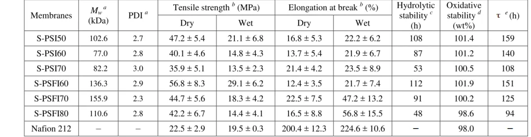
Table 1. Molecular weight, mechanical properties, hydrolytic and oxidative stability of S-PSI and S-PSFI membranes 1 Membranes Mw a (kDa) PDI a Tensile strength b
(MPa) Elongation at break b (%) Hydrolytic stability c (h) Oxidative stability d (wt%) e (h)
Dry Wet Dry Wet
S-PSI50 102.6 2.7 47.2 ± 5.4 21.1 ± 6.8 16.8 ± 5.3 22.2 ± 6.2 108 101.4 159 S-PSI60 77.0 2.8 40.1 ± 4.6 14.8 ± 4.3 13.7 ± 5.4 21.9 ± 6.7 87 101.2 140 S-PSI70 82.2 3.0 35.9 ± 5.1 13.5 ± 2.3 21.4 ± 4.2 23.5 ± 8.9 53 100.5 108 S-PSFI60 136.3 2.9 56.8 ± 8.3 29.1 ± 6.2 12.4 ± 3.5 21.7 ± 7.4 112 101.9 151 S-PSFI70 155.9 2.3 44.7 ± 5.6 18.3 ± 4.2 22.5 ± 7.5 47.2 ± 13.2 91 100.2 125 S-PSFI80 110.6 2.8 42.2 ± 6.7 14.4 ± 4.1 16.5 ± 8.8 56.8 ± 15.5 48 98.6 94 Nafion 212 22.5 ± 2.9 19.5 ± 0.3 200.4 ± 12.3 224.6 ± 10.6 98.0 2 a
Determined by GPC using NMP with 0.05 M LiBr. b Measured at 30 oC. c The time of membranes maintain mechanical properties at 100 oC 3
in water. d Retained weight percent of membranes after Fenton`s test. e The time at which the membranes dissolved completely in Fenton`s 4 reagent at 30 oC. 5 6 7 8 9 10 11
28 1
Figure 2. TGA curves of S-PSI and S-PSFI copolymers under N2 atmosphere
2 3 4 5 6 7 8 9 10 11 12 13
29 1
Figure 3. TEM phase images of S-PSI and S-PSFI membranes 2 3 4 5 6 7 8 9 10 11 12 13 14
30 1
Figure 4. Chemical structure and 3D models of (a) S-PSI60 and (b) S-PSFI70 copolymers 2
with 60 repeating units 3 4 5 6 7 8 9 10 11 12 13 14 15
31
Table 2. Density, ion exchange capacity (IEC), water uptake and retention of S-PSI and S-PSFI membranes 1
Membranes Density
a
(g cm-3)
IECw (meq.g-1) IECv (meq.cm-3) WU(wt%) WU(Vol%) Water
retention (%) cal b tit c dry wet 30 oC 100 oC 30 oC 100 oC
S-PSI50 1.45 1.53 1.49 2.17 1.67 20.9 29.3 30.2 42.5 3.49 S-PSI60 1.47 1.73 1.71 2.51 1.84 24.6 35.4 36.2 52.0 5.31 S-PSI70 1.48 1.91 1.87 2.77 1.97 27.3 40 40.4 59.2 4.91 S-PSFI60 1.45 1.51 1.47 2.13 1.63 21.2 34.9 30.7 50.5 3.25 S-PSFI70 1.46 1.73 1.70 2.48 1.82 24.8 37.9 36.2 55.3 3.85 S-PSFI80 1.46 1.94 1.89 2.76 1.97 27.7 40.3 40.4 58.8 4.14 Nafion 212 1.97 0.92 0.98 1.93 1.28 21.6 42.6 5.69 2 a
Measured at 30 oC. b Calculated ion exchange capacity (IEC) values. c Determined by titration. 3 4 5 6 7 8 9
32 1
Figure 5. IECw dependence of dimensional swelling ratio and relationship between in-plane
2
and through-plane changes at 100 oC 3 4 5 6 7 8 9 10 11 12 13 14 15
33 1
Figure 6. In-plane and through-plane proton conductivity of S-PSI and S-PSFI membranes as 2
a function of IECw at 80 oC , 100 % RH (1.5 atm), (b) 100 oC, 85% RH (1.5 atm) and (c) 120
3
o
C, 35% RH (1.5 atm), (ღ,ყ indicates in-plane and through-plane conductivity of Nafion 4 212 respectively) 5 6 7 8 9
34 1
Figure 7. H2/air Single cell performances of S-PSI and S-PSFI membranes as a function of
2
the current density at various temperature and RH 3


![[PDF] Cours SECURI ITE RESEAUX en PDF | Cours informatique](data:image/gif;base64,R0lGODlhAQABAIAAAP///wAAACH5BAEAAAAALAAAAAABAAEAAAICRAEAOw==)