HAL Id: hal-01619256
https://hal.archives-ouvertes.fr/hal-01619256
Submitted on 30 Mar 2018
HAL is a multi-disciplinary open access
archive for the deposit and dissemination of
sci-entific research documents, whether they are
pub-lished or not. The documents may come from
teaching and research institutions in France or
abroad, or from public or private research centers.
L’archive ouverte pluridisciplinaire HAL, est
destinée au dépôt et à la diffusion de documents
scientifiques de niveau recherche, publiés ou non,
émanant des établissements d’enseignement et de
recherche français ou étrangers, des laboratoires
publics ou privés.
Oxidative pyrolysis of wood chips and of wood pellets in
a downdraft continuous fixed bed reactor
Elias Daouk, Laurent Steene, Frederic Paviet, Éric Martin, Jeremy Valette,
Sylvain Salvador
To cite this version:
Elias Daouk, Laurent Steene, Frederic Paviet, Éric Martin, Jeremy Valette, et al.. Oxidative pyrolysis
of wood chips and of wood pellets in a downdraft continuous fixed bed reactor. Fuel, Elsevier, 2017,
196, pp.408-418. �10.1016/j.fuel.2017.02.012�. �hal-01619256�
Oxidative pyrolysis of wood chips and of wood pellets in a downdraft
continuous fixed bed reactor
Elias Daouk
a,b,c,⇑, Laurent Van de Steene
a, Frederic Paviet
c, Eric Martin
a, Jeremy Valette
a, Sylvain Salvador
baCIRAD – UR BioWooEB, 73 Avenue Jean-François Breton, 34398 Montpellier Cedex 5, France bRAPSODEE, CNRS UMR 5203, Mines-Albi, Campus Jarlard, 81013 Albi Cedex 09, France
cGEPEA, UMR 6144 CNRS, Université de Nantes, Ecole des Mines de Nantes, ENITIAA, DSEE, 4 rue Alfred Kastler, BP 20722, 44307 Nantes Cedex 3, France
h i g h l i g h t s
!A counter-current oxidation zone was stabilized inside a downdraft reactor. !Detailed mass balance including char, permanent gases and tar yields. !The fed air flow rate and the fuel (wood) density were varied. !Insights acquired on the shape and stability of the oxidation zone.
Keywords: Oxidative pyrolysis Fixed-bed Biomass Smoldering Yields of products
a b s t r a c t
In air staged gasification and advanced carbonization processes, oxidative pyrolysis occurs in downdraft continuous fixed bed reactors. An oxidation zone separates the virgin fuel from the resulting char and propagates upward. Here, the oxidation zone was stabilized at a fixed elevation in a 20 cm I.D. fixed bed reactor using wood chips or wood pellets. In controlled continuous operating mode, we investigated the impact of air flux and bed bulk density on the behavior of the oxidation zone in terms of wood con-sumption, and yields of char, gas and tars. An air:wood mass ratio of 0.7 was measured and in our oper-ating conditions, and was not sensitive to air mass flux and bed density. With oxidative pyrolysis, yields of organic condensates were lower than with allothermal pyrolysis, whereas the production of pyrolysis water and permanent gases increased. Finally, the oxidation zone was shown to be flat and horizontal in a wood pellet bed but inclined in a wood chip bed.
1. Introduction
Thermochemical biomass conversion, i.e. combustion, gasifica-tion, and pyrolysis, can convert a biomass into useful energy such as heat, electricity, or liquid fuel. Although biomass combustion has clearly reached the commercial development stage, the trajec-tories of the two other routes are quite different.
Pyrolysis was widely developed for charcoal production, also called carbonization, in the past, but in most cases, the technolo-gies remain simple and robust and not always adapted to the need
for efficiency and environmental constraints today[1].
Neverthe-less thanks to the awareness of some constructors, but also due to the new interest in charcoal as reducing agent, fertilizer, or
active carbon, the technologies have been significantly improved in recent years.
Research and development programs on gasification have been underway for many years; some commercial demonstrations exist, but the technology positioning in the market remain fragile and
the success stories still limited[2]. Nevertheless, a wide range of
reactors have been developed varying mainly in their feedstocks and applications. Usually, a simple classification is proposed based on the size of the installation: entrained flow, fluidized bed, and fixed bed reactor, for large, medium and small reactors, respec-tively. Fixed bed reactors are widely acknowledged to be the best solution for low power production because of their greater simplic-ity and lower production cost.
In many of the above mentioned carbonization and small scale staged gasification processes, biomass pyrolysis occurs in a specific continuous downdraft fixed bed configuration. But in the same way as in any thermochemical conversion processes, pyrolysis plays a major role as it produces char and pyrolysis gases that ⇑Corresponding author at: CIRAD – UR BioWooEB, 73 Avenue Jean-François
Breton, 34398 Montpellier Cedex 5, France.
are subsequently converted. Moreover, partial oxidation can be a simple and efficient way to sustain pyrolysis, by providing the energy needed for heating, drying, and endothermic reactions of the conversion, and to allow the process to be autothermal: it is thus referred here as oxidative pyrolysis.
During pyrolysis in continuous downdraft reactors, the biomass and air are fed into the top of the reactor and char and pyrolysis gases are removed from the bottom. We define the oxidation zone as the reactive zone inside the packed bed where major changes in
temperature and gas composition take place (Fig. 1). This zone
sep-arates the unreacted biomass from the char and is the location of several complex and coupled transformations or reactions. The first to occur is drying. When the temperature increases, oxidative pyrolysis occurs, which can be defined as a combination of biomass
oxidation and biomass pyrolysis[3]. Then, oxidation of some light
and heavy pyrolysis gases, and of char, provides the energy to the system, and thus allows the propagation of the oxidation zone.
The stabilization of the oxidation zone inside the bed is of par-ticular interest for operators because (i) the top of the bed is main-tained at a low temperature, thereby facilitating control of the process and limiting the production and deposition of tar, and (ii) a higher temperature zone is created that favors tar cracking when crossing it.
The upward propagation of the oxidation zone towards the vir-gin biomass can be controlled by removing char from the bottom of the reactor, which causes a downward movement of the whole bed. The propagation of an oxidation zone in a porous medium, called smoldering, has been studied in many contexts, including
forest fires and tree trunk combustion[4,5], home fires and
burn-ing of polymeric foams or tissue[6], propagation of underground
fires in coal mines[7]or in oil shale exploitation[8], organic waste
incineration[9,10], and also during combustion of cigarettes[11].
These configurations differ in several respects. In particular the
two first examples[4–6]refer to natural smoldering, as opposed
to forced smoldering [7–11], which describes situations where
the air flow is forced to cross the porous media, as in packed bed incineration and oil shale combustion. Moreover, forced smolder-ing is classified as reverse (counter-current) or forward (co-current) depending upon the relative directions of the air and of the propagation of the oxidation zone in the porous medium.
In forward smoldering[7,8,11]the oxidation zone moves in the
same direction as the air flow. In reverse smoldering, it propagates in the opposite direction to that of the air mass flux, meaning that
air first crosses the unreacted carbonaceous material[9,10,12–14].
The oxidative pyrolysis of wood chips in a continuous fixed bed investigated here involves forced reverse smoldering because oxi-dation zone propagates upwards, in opposite direction to wood
and air flows[15].
In smoldering, the oxidation zone can be described by several specific features: - its propagation rate; - its temperature; - its geom-etry, thickness and shape; - its yield of char, gases, and tar, and the composition of these outputs. These features can be observed experimentally using the appropriate research equipment. Their prediction remains a real challenge for researchers, as they require the elaboration of complex models combining a description of chemical reactions with heat and mass transfer phenomena.
Among these features, the propagation rate of the oxidation zone has been widely investigated in the literature on reverse
smoldering[10–15]. It should be noted here that when referring
to propagation rate or velocity, the terms ‘‘front” or ‘‘ignition front” are more commonly used by authors than oxidation zone. The propagation rate, which is controlled by combustion and heat and mass transfers, depends on: - air flow-rate; - fuel properties like size, density, thermal conductivity, moisture, volatile matter, ash, and elemental composition; - and bed properties, such as porosity and density. However, as mentioned by Mahapatra and
Dasappa[12], not all of these parameters are independent
vari-ables and most are interrelated, so that drawing conclusions about the dependence of each separate parameter on the behavior of the oxidation zone is very difficult.
Nevertheless, there is a consensus in the literature that air mass flux is the parameter that has the most influence on the propaga-tion rate. This point has been checked on more than 10
carbona-ceous feedstocks with significantly different properties [13,16].
Regarding the influence of the air mass flux, the propagation rate inside a wood packed bed initially increases as the air mass flux increases until it reaches a peak. A further increase in the air mass flux then results in a decrease of the propagation rate. Three differ-ent regimes are usually iddiffer-entified in reverse smoldering applied to the combustion process, which are determined by the main pro-cess controlling the propagation of the front: oxygen-limited,
reac-tion limited and quenching by convecreac-tion[13,16,17].
Air mass flux does not only influence the propagation rate, but also the other features of the oxidation zone. It has been shown that peak temperature in the zone increases with an increase in the air flux until a maximum is reached in the sub-stoichiometric
condi-tions of the combustion regime[13]. An increase of about 100!C
in temperature has been reported when air mass flux fed through a wood downdraft batch gasifier was increased from 0.12 to
0.14 kg m"2s"1[12]. In these studies, these maximum
tempera-tures match the maximum propagation rates of the oxidation zone. Regarding geometry, some authors have attempted to measure the thickness of the ignition zone in counter current combustion processes. It has been reported to be in the same order of
magni-tude as particle size[14,16], and is said not be sensitive to the
air flux[14].
The influence of the biomass or bed properties has been more rarely investigated. But the few studies that did showed that front
propagation velocity was higher when: - particle size[13,16,17]
or water content[10,13,17]or ash content[13]was low; or - when
the heating value[13,17]was high. Moreover, ignition front speed
was shown to be inversely proportional to bed bulk density[16,18].
From the previous literature on reverse smoldering, the follow-ing remarks can be made. First, most of the studies focused on understanding the propagation rate. Other specific features of the oxidation zone received less attention, in particular, the geometry of the oxidation zone and yields and the composition of all the products leaving this zone. Second, very little information is avail-able on the influence of operating parameters and fuel/bed proper-ties on the features of the whole oxidation zone, and more
quantitative results would be useful to enhance our understanding. And finally, all previous works mentioned here were performed
under batch conditions, and, all except one[12], involve a
down-draft movement of the oxidation zone. Thus, reverse smoldering in a continuous downdraft fixed bed reactor has never been specif-ically investigated.
This research report focuses on the oxidative pyrolysis of wood in a continuous fixed bed reactor, characterized by a downward reverse smoldering configuration. The objective of the study was to quantify the impact of two parameters of major importance: the air mass flux and the bulk density of the packed bed, on the fea-tures of the oxidation zone. We focus on the measurement and observation of the following specific features of the oxidation zone: - yields and the composition of char, gas, and tar produced; - and its shape.
Results of this study give a new insight on reverse smoldering in continuous downdraft fixed bed reactors. Data provided could be useful for researchers for the validation or development of CFD models. Regarding applicability, the works presented provide a better understanding of the behavior of the oxidative pyrolysis stage in staged fixed-bed gasification or carbonization processes and may support constructors and operators in optimization of their process design and operation.
The experimental results presented in this paper were obtained in a stationary regime. The oxidation zone was stabilized at a given elevation in a continuous downdraft fixed bed reactor with differ-ent air mass fluxes and bed densities. The air mass fluxes were selected in a range appropriate for the oxidative pyrolysis step of air staged gasifiers. We tested two types of wood, chips and pellets, which differ considerably in particle size and density, both of which are of major interest for different applications.
2. Experimental device and procedures 2.1. Description of the reactor
A continuous fixed bed reactor (CFiBR) developed by CIRAD was used for this study. This reactor was originally designed to study
char gasification[19–21]. Later on, Milhé et al.[15], adapted the
reactor to study the auto-thermal and allothermal pyrolysis of
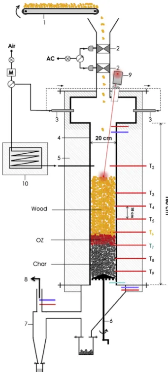
wood chips.Fig. 2shows the experimental setup. It is mainly
com-posed of the reactor tube, the feeding system and the extraction system. The reactor tube, made of refractory stainless steel, has an internal diameter of 20 cm and is 160 cm long. It is equipped with eight tapping pipes with 1 mm thermocouples fitted length-wise to the reactor at 10 cm intervals. A sampling pipe is located in the lower part of the reactor to collect gases at the outlet. Wood particles are supplied through the top of the reactor via a 2 m long conveyor belt and two pneumatic valves that act as an airlock. Wood particles are supported by a grid at the bottom of the reactor to form a fixed bed at a height of about 80 cm. The height of the bed is controlled by a laser beam device connected to the feeding system. Energy to support front propagation is supplied by air injected through the top of the reactor to feed the oxidation zone (OZ) in the bed. Wood is converted to char, tars and gases. Char is removed from the bottom of the reactor manually using a scra-per, while all the gases flow through a heated pipe to a post-combustion chamber via a cyclone to separate the fines.
2.2. Sampling train
Fig. 3shows the sampling train designed to measure the tar and
the permanent gas flow rates together with their compositions. The sampling train is connected to the reactor via the sampling pipe located below the grid supporting the fixed bed. Gaseous
products first flow through a series of 6 impingers. The first two are empty and at ambient temperature; the water can condensate to prevent plugging due to water freezing in the cold bath. The fol-lowing three are immersed in a bath cooled to about "20 !C. The first contains isopropanol; the second also contains isopropanol but is also equipped with quartz frit, while the third is only pro-vided with a quartz frit. The last impinger is filled with silica gel to trap the last traces of water and to protect the downstream gas analyzer. The gas then successively passes through the pump, the gas flow meter, and a micro-gas chromatography system (micro-GC). The latter is equipped with two columns to measure the concentrations of permanent gases (N2, O2, CO, CO2, H2, CH4, C2H4 and C2H6) at the gas outlet.
Fig. 2. Schematic diagram of the CFiBR. (1) Conveyor, (2) airlock, (3) fresh air supply, (4) reactor tube, (5) insulation, (6) char removal device, (7) cyclone, (8) to post combustion, (9) laser, (10) air preheater.
2.3. Operating mode 2.3.1. Starting step
In autothermal pyrolysis experiments, the heat necessary to dry and pyrolyze the wood chips is supplied by combustion in the so called ‘‘oxidation zone” in the fixed bed. First, the oxidation zone is ignited at the surface of a thin layer char bed at the bottom of the reactor by an external energy source and ambient air is injected at the top of the reactor at a sufficiently high flow rate to maintain combustion. In our experiment, the external energy source con-sisted in some burning barbecue-lighter particles dropped onto the surface of the layer of charcoal. After ignition of the oxidation zone, the air flow rate from the top of the reactor was reduced to the value to be investigated in the test, and the reactor was filled with wood chips or wood pellets to a height of about 80 cm from the bottom grate. The oxidation zone then spreads upward. The rise in the OZ is monitored by observing the increase in the temperature measured along the bed. When the OZ reaches the height required for the test, it is maintained more or less still, as described below. 2.3.2. Control of the oxidation zone inside the fixed bed
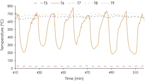
The main challenge of this type of experiment is keeping the oxidation zone at a fixed elevation while continuously feeding wood and removing char. In our case, we chose an oxidation zone close to the middle of the total height of the solid bed, i.e. 35 cm above the grid holding the bed, where thermocouple T6 was
posi-tioned (Fig. 4). When the temperature recorded by T6 increased
and reached the same value as the thermocouple positioned 10 cm below (T7), we manually extracted char from the bottom of the reactor. The OZ then descended a few millimeters in the
reactor due to the downward movement of the fixed bed. Thermo-couple T6 recorded a sudden drop when it again came into contact with cold biomass. Next, the OZ rose again in the reactor. When the temperature recorded by T6 again reached the same value as T7, we extracted more char. Temperatures T7 to T9 varied slightly
between 650!C and 700 !C. Temperature T5, in the wood chips,
remained constant at close to room temperature.
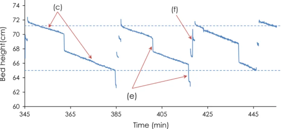
Because char is extracted and the bed compacted, total bed height decreases. The reactor has to be filled regularly to maintain a constant total bed height. To make this possible, a laser device was installed above the reactor to continuously measure the height
of the bed.Fig. 5shows the impact of bed compaction, char
extrac-tion, and wood reloading on the bed height during the course of the experiment. In this case, total bed height was between 65 and 72 cm. Wood reloading stopped automatically when the bed height reached the appropriate height and started again when the level dropped too low.
2.3.3. Mass balance
Nitrogen from the introduced air ( _mN2;i) was used as a tracer to
calculate the total mass flow rate of permanent gases ( _mpg) at the
outlet of the reactor according to Eq. (1):
_ mpg¼
_ mN2;i
YN2;o ð1Þ
YN2;o, which represent the nitrogen mass fraction in the
perma-nent gases produced, was determined using the fraction measured
by the micro-GC. The mass flow rates of each component ( _mj;o) in
the permanent gases in the outlet was calculated using the Eq. (2):
Fig. 3. Sampling train. (1) heated conduit, (2) empty impingers, (3) isopropyl alcohol impingers, (4) quartz frit impinger, (5) silica gel impinger, (6) cold bath at "20 !C (7) pump, (8) flow meter, (9) gas meter, (10) micro-GC.
0 100 200 300 400 500 600 700 800 410 430 450 470 490 510 Temperature (° C) Time (min) T5 T6 T7 T8 T9
_
mj;o¼ Yj;om_pg j ¼ N2; O2; H2; CO; CO2; CH4; C2H4; C2H6 ð2Þ
After sampling for about an hour, the impingers were weighed and the mass flow rate of sampled tars was calculated, assuming that the ratio of the tars to the permanent gas is the same in the total outlet gas as in the sampled gas (Eq. (3)):
_
mt;o¼ _mpg mm__t;o pg ! "
samp: ð3Þ
The water mass fraction in the tars was determined using the Karl-Fischer technique.
Repeatability tests were performed for the experiment with an
air flux of 0.022 kg m"2s"1. The mass balances for the three
exper-iments are listed inTable 1. A comparison of the mass flow-rates
for each component of the three tests shows that repeatability was good. In addition, the mass balances were satisfactory. A max-imum difference of 7% was measured between the masses of incoming and outgoing products. We can therefore consider that the methods used to determine the different mass-flow rates were reliable.
2.4. Characteristics of the wood chips and wood pellets
Wood chips and wood pellets of maritime pine (Pinus pinaster)
with bark were used for the experiments.Table 2shows the results
of proximate and ultimate analyses measured in compliance with standards. The wood chips and wood pellets can be considered similar in terms of composition. The bulk density for wood chips
was 220 kg/m3 and around 690 kg/m3 for the wood pellets. The
size distribution of the wood chips was determined by the horizon-tally oscillating screen method according to EN15149-1. Around 80 wt% of the wood chips were within the 1–8 mm size range. The cylindrical wood pellets were homogeneous in size, with a diameter of 6 mm of diameter and a length of around 20 mm.
3. Results and discussion 3.1. Mass balances and yields
Results obtained in the reference conditions, i.e., wood chips as
feedstock and an air flux of 0.022 kg m"2s"1, are presented in this
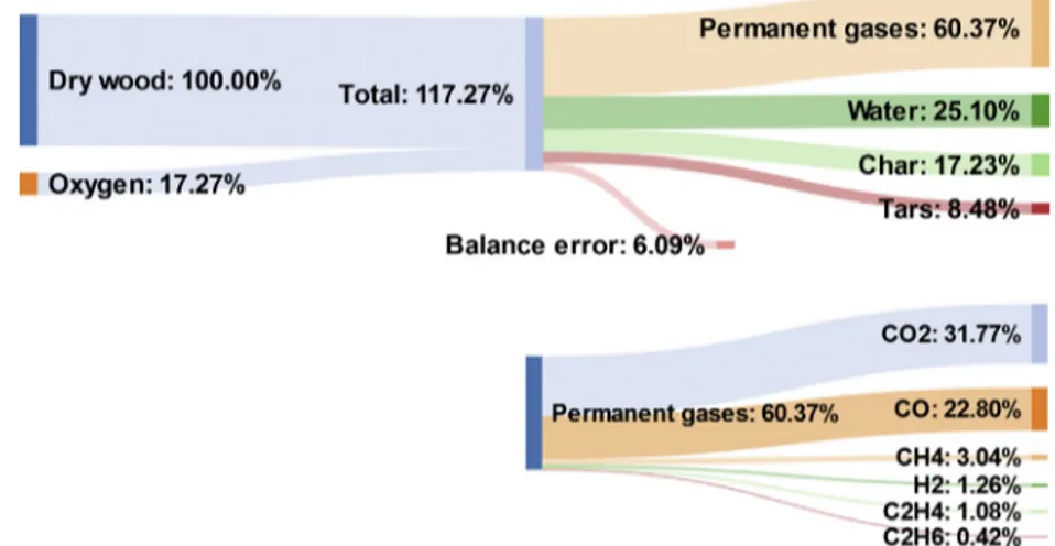
section. The mass balance and the distribution of the products between permanent gases, water, char and tars at the outlet are
shown in Fig. 6, along with the composition of the permanent
gases. The yield of each product was estimated as a percentage of the initial mass flow rate of dry wood chips. The total of mea-sured yields is thus >100%, as the oxygen mass introduced at the top of the reactor reacts in the bed and was recovered in the prod-ucts. As the results are presented relative to initial dry wood, dry-ing water was not included in the mass balance of outgodry-ing products. Nitrogen, as an inert gas, was also removed from the mass balances.
In general, the mass balance at closure was satisfactory. The slight difference (around 6%) between the inlet and the outlet
60 62 64 66 68 70 72 74 345 365 385 405 425 445 Bed hei ght( cm) Time (min)
(e)
(c) (f)Fig. 5. Changes in bed height over the course of an experiment. (c) bed compaction, (e) char extraction, (f) wood filling.
Table 1
Repeatability of the mass balance for the experiment with wood chips and an air flux of 0.022 kg m"2s"1. The difference is calculated relative to the inlets.
Flow rate (kg/h) Test 1 Test 2 Test 3
Inlets Wood 3.720 3.780 3.618 Air 2.630 2.630 2.630 Total 6.350 6.410 6.248 Outlets Char 0.570 0.582 0.572 Permanent gases 4.122 4.048 4.033 Tars 0.297 0.247 0.304 Water 1.263 1.111 1.250 Total 6.252 5.988 6.159 Difference 1.54% 6.58% 1.42% Table 2
Ultimate and proximate analyses of the wood chips and wood pellets.
Wood chips Wood pellets Moisture (wt%, w.b.) 9.8 8 Proximate analysis (wt%, d.b) Ash 0.4 0.4 Volatile matter 83.7 83.3 Fixed carbon 15.9 16.3 Ultimate analysis (wt%, d.b.) C 49 51.7 H 7.2 7.1 N 0.1 0.1 O (by difference) 43.7 41.1 LHV (MJ/kg, d.b.) 18.3 19.1
can be attributed to errors in the calculation of flow rates for the solids, permanents gases, and tars.
In the case of wood chips, considering an air flux of
0.022 kg m"2s"1, the corresponding wood flux is 0.030 kg m"2s"1.
The resulting yields of outgoing products were 17.2 wt% char, 25.1 wt% water, 8.5 wt% tars, and 60.4 wt% permanent gases.
These results show that the yield of tar from oxidative pyrolysis, 8.5 wt%, is very low compared to pyrolysis in inert atmosphere. In a
previous study by the same research team[15], a tar yield of 31 wt
% was measured during inert atmosphere pyrolysis at 575!C in the
same fixed bed reactor. The low yields of tar during oxidative pyrolysis can be attributed to several reactions that may occur:
– Thermal cracking and oxidation in the oxidation zone, where
the temperature is higher (700!C for an air flux of
0.022 kg m"2s"1) than in the one during inert pyrolysis
(575!C).
– Tar cracking in the char bed zone, where heterogeneous and homogeneous reactions on the surface of the char take place. Naturally, such cracking reactions are effective only if tempera-ture and residence time of tars are high enough. Here, the resi-dence time of tars in the oxidation and char zones bed was about
three seconds, and temperatures varied between 650!C and
700!C. Previous studies have shown that above 500 !C and with
a residence time of tar around 2–3 s, heterogeneous cracking reac-tions of tars are significant and result in a higher yield of
perma-nent gases and a lower yield of condensable vapors[15,22].
Finally,Fig. 6shows that the yield of pyrolysis water was higher
here (25 wt% for an air flux of 0.022 kg m"2s"1) than during inert
allothermal pyrolysis (15 wt%). This can be attributed to oxidation and/or cracking reactions in the oxidation zone and char bed zone. 3.2. Product analyses
In this section, the analyses of the products from the
experi-ments with wood chips and an air flux of 0.022 kg m"2s"1 are
detailed. 3.2.1. Char
The results of ultimate and proximate analyses of the char
pro-duced during the experiment are summarized in Table 3. The
resulting char contained more than 94% of carbon.
Volatile matter (VM) content of chars is of particular interest for gasifier optimization. As the char produced during pyrolysis is gasi-fied in the subsequent step of the process, it is extremely important
that the VM content remains as low as possible in order to avoid the release of organic compounds in the syngas. From this point of view, the char produced by oxidative pyrolysis is of particular interest. The main reason is the higher temperature reached during pyrolysis due to in-situ oxidation. Indeed, a previous study by the same authors
[15]showed that the influence of the oxidation reaction on char
quality was not significant and that the temperature was the param-eter that had the most influence. This low VM content is also respon-sible for the high LHV measured on the resulting char.
3.2.2. Permanent gases
The mass yields of permanent gases during the experiment are
presented inFig. 6. The composition of the gas calculated on the
basis of dry wood was 31.8% CO2, 22.8% CO, 1.3% H2, 3% CH4, 1%
C2H4, and 0.4% C2H6. The yields of CO, CO2, and H2 measured
dur-ing oxidative pyrolysis were higher than those measured durdur-ing
inert pyrolysis[15,23].
On a permanent gas volume basis (including nitrogen), the
composition of the gases at the outlet was 47.5% N2, 15.8% CO2,
17.6% CO, 13.8% H2, 4.1% CH4, 0.9% C2H4, and 0.3% C2H6.
3.2.3. Tars
To date, several definitions of tars can be found in the literature
[24]. Tars are composed of hundreds of condensable organic
com-pounds. Today, it is not possible to identify and to quantify all the molecules because many of them are only present in trace
amounts. Devi et al.[23]defined tars as a complex mixture of
con-densable hydrocarbons, containing one to several aromatic rings and other oxygenates and polycyclic aromatic hydrocarbons (PAHs). Tars are very frequently classified in three categories
[24–28]:
Fig. 6. Mass flow diagram of the experiment with wood chips and an air flux of 0.022 kg m"2s"1. Yields are expressed in wt% relative to the initial dry wood.
Table 3
Proximate and ultimate analysis of the char produced during the experiment with wood chips and an air flux of 0.022 kg m"2s"1.
Proximate analysis (wt%, d.b) Ash 1.2 ± 0.2 Volatile matter 4.2 ± 0.5 Fixed carbon 94.6 ± 0.7 Ultimate analysis (wt%, d.b.) C 94.9 ± 0.5 H 1.9 ± 0.25 N 0.55 ± 0.05 O (by difference) 2.65 ± 0.75 LHV (MJ/kg, d.b.) 34 ± 0.12
! Primary products: cellulose-derived products, hemicellulose-derived products and lignin-hemicellulose-derived products (levoglucosan, hydroxyacetaldehyde, furfurals, methoxyphenols). These tars
are produced at low temperatures (400–500!C) with a short
residence time.
! Secondary products: phenolics and olefins. These products are
produced at moderate temperatures (600–700!C) with a
med-ium residence time.
! Tertiary products: methyl derivatives of aromatics (methyl ace-naphthylene, methylnaphthalene, toluene and indene), and polycyclic aromatic hydrocarbons (PAHs) (benzene, pyrene, naphthalene, acenaphthylene, anthracene, phenanthrene).
These tars are produced at high temperatures (800–900!C)
with a longer residence time.
More than 70 organic compounds were identified and quanti-fied using the GC–MS. Despite our team’s experience in condensate analysis, only about 40 wt% of the organic condensates were quan-tified in the collected samples. This can be due to the existence of a huge number of minor compounds that are either co-eluted with similar molecules, or present at too low concentrations to be iso-lated in the chromatograph. Furthermore, pyrolytic lignin can be present in the sampled tars and is not quantified by
chromatogra-phy. Dufour et al.[28]obtained similar results by quantifying up to
40 species in the pyrolysis condensates produced in a batch fixed-bed reactor. These species represented 40 and 43 wt% of the
organic condensates produced at final temperatures of 325!C
and 625!C respectively.
Condensates from oxidative pyrolysis of wood chips are listed
inFig. 7. Some quantified compounds were grouped in the
follow-ing chemical families: phenols, guaiacols, furans, and PAHs. They are shown as a percentage of the mass of the dry wood chips. From the detected organic compounds in the tars, we observed that 57 wt% of them belong to primary group and the rest, 43 wt%, belong to secondary and tertiary groups. Compared with the
liter-ature[29,30], the majority of the organic compounds detected in
inert atmosphere belong to the group of primary tars when they are extracted directly after the devolatilization of the biomass.
For example, Milhé et al. [15] found that for inert pyrolysis at
475!C, more than 98 wt% of the detected tars belong to primary
group. We can thus confirm the occurrence of tar cracking and oxi-dation reactions during our experiments, resulting in more sec-ondary tars and fewer primary tars than during inert pyrolysis. It is noteworthy that tertiary tars (PAHs), the most stable, accounted
only for a minor part. This is due to the temperature (<800!C) in
the bed that does not allow the formation of heavier tertiary aromatics.
3.3. Effect of air flux
As mentioned above, air flux is known to be the most influential parameter in the front propagation rate. Indeed, the literature on
reverse smoldering [13,16,17], cited three different regimes,
depending on the main process controlling the propagation: oxygen-limited, reaction limited and quenching by convection.
These regimes are clearly illustrated inFig. 8by the plot of wood
chip flux versus air flux from the study of Porteiro et al.[13]. First
there was a linear increase in the fuel flux with an increase in the air flux. Next, in the second zone, variations in the air flux did not influence the wood flux. Last, beyond a certain air flux, the wood flux decreased significantly until extinction of the front due to cooling of the reaction front by convective heat transfers.
The influence of air flux on the wood flux was investigated using both wood chips and wood pellets. Three air fluxes were
tested: 0.014 kg m"2s"1, 0.022 kg m"2s"1, and 0.029 kg m"2s"1.
Fig. 9shows the results in terms of the wood flux as a function
of air flux. Fig. 8 [13]shows that our study was in the
oxygen-limited regime as the relation between the wood and air mass fluxes was almost linear. In industrial applications, smoldering regime must be in the oxygen-limited zone in order to control
0.0% 0.1% 0.2% 0.3% 0.4% 0.5% 0.6% 0.7% Yi eld (wt .% of dry wood )
Fig. 7. Yields of organic condensates produced during the experiment with wood chips and an air flux of 0.022 kg m"2s"1.
the input fuel power of the process by a simple regulation of the air flux.
The air: wood mass ratio is an essential parameter for process operation and optimization. With wood chips, this ratio was 0.61,
0.73, and 0.73 for air fluxes of 0.014, 0.022 and 0.029 kg m"2s"1
respectively (Table 4). With wood pellets, the ratio was
respec-tively 0.54, 0.68, and 0.67 for the three air fluxes considered. These results show that these ratios were lower with the low air flux, and remained constant with the two higher air fluxes. Thus, it appears that less air is consumed for a given progress of the oxidation zone when the injected air flux is low. The lower temperatures mea-sured in that case may lower the oxidation kinetics and could be a first explanation. But comprehensive understanding cannot be stated only based on this experimental study. Indeed the progress of the oxidation zone is controlled by many phenomena, including chemical reactions, mechanical compaction, heat and mass trans-fers. Only a modelling approach to separate the impact of each phenomenon could provide answers. Nevertheless, the air: wood mass ratios were all between 0.54 and 0.73 in our operating condi-tions. Given that in stoichiometric conditions, this ratio is about 5.4 kg/kg, we can conclude that in our autothermal experiments, the oxidation zone consumes between 10% and 13.5% of the stoi-chiometric air to convert wood into char and gas.
Regarding the distribution of the products leaving the reactor, char yields decreased with an increase in the air flux. As can be
seen inTable 4, increasing the air flux from 0.014 to 0.029 kg m"2
-s"1char reduced the yield from 19.8% to 16.3%, for wood chips, and
from 20.9% to 16.5% for wood pellets. The char yield in wood
pyrol-ysis depends on many factors[31]. The most important factors in
our case are the heating rate and the final temperature.
Table 4also shows that the higher the air flux, the higher the
temperature of the OZ: it increased by about 100!C when the air
flux was increased from 0.014 to 0.029 kg m"2s"1. Anca-Couce
[31] showed that higher temperatures achieved in the reactor
reduce the char yield. Moreover, it is likely that the rising in tem-perature and the acceleration of the OZ observed tend to increase the wood heating rate, which is also known to lower the char yield
[28].
3.4. Effect of wood bulk density
The effect of wood density was investigated by comparing wood chips (WC) and wood pellets (WP). These two most common types of processed wood differ significantly in their bulk densities:
220 kg/m3for WC and 690 kg/m3for WP, i.e. a ratio of more than 3.
In the previous section (Fig. 9), it was shown that, despite the
marked difference in the two wood densities, the difference in the air: wood ratio between wood chips and wood pellets is not so high. The yield distribution of the products of the two types of
wood (Table 4) was also similar, except for water and some
perma-nent gases yields (mainly CO, CO2, CH4, and H2) whatever the air
flux used. For the same air flux, the temperatures in the reactor were higher with WP than with WC. For example, with an air flux
of 0.022 kg m"2s"1, the mean OZ temperature was 680 and 700!C
respectively for WC and WP. This could be attributed to the struc-ture of the OZ which depends on wood density. This temperastruc-ture difference between WC and WP affects directly the kinetics of many reactions involved during pyrolysis, char gasification, oxida-tion (of wood, char, gas and tars), and water-shift. Thus, further explanation on the correlation between OZ temperature and yields of gases and water would require a detailed modelling approach.
The main difference between wood chips and wood pellets in the experiments was the upward velocity of the oxidation zone, which was much higher with wood chips than with wood pellets. We calculated the velocity of the oxidation zone during our exper-iment from the measurement of the wood mass flux and the wood bulk density as follows:
v
OZ¼/q
w w ð4Þ 0 0.01 0.02 0.03 0.04 0.05 0 0.005 0.01 0.015 0.02 0.025 0.03 W oo d fl ux( kg.m -2s -1 Air flux (kg.m-2s-1) PF Gran. WC WP (Fig. 9. Wood flux as a function of air flux for the two types of wood, wood chips (WC) and wood pellets (WP). Dashed line is for stoichiometry condition.
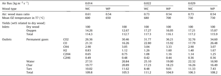
Table 4
Air: wood ratio, OZ temperature, and product yields for the two types of wood and three differen4t air fluxes.
Air flux (kg m"2s"1) 0.014 0.022 0.029
Wood type WC WP WC WP WC WP
Air: wood mass ratio 0.61 0.54 0.73 0.54 0.73 0.54
Mean OZ temperature in T7 (!C) 600 650 680 700 730 730 Yields (wt% related to dry wood)
Inlets Dry wood 100 100 100 100 100 100
Oxygen 14.26 12.67 17.27 16.05 17.21 15.87
Total 114.3 112.7 117.3 116.1 117.2 115.9
Outlets Permanent gases CO2 26.36 30.46 31.77 36.21 32.76 34.60 CO 21.31 16.26 22.80 15.92 17.79 26.48 CH4 2.90 3.05 3.04 3.33 2.90 3.07 H2 0.83 1.12 1.26 1.60 1.40 1.67 C2H4 0.65 0.75 1.08 1.16 1.14 1.25 C2H6 0.49 0.48 0.42 0.44 0.36 0.36 Water 27.51 20.84 25.10 19.00 22.32 16.90 Char 19.77 20.89 17.23 18.23 16.26 16.49 Tars 10.02 11.62 8.48 9.01 11.33 7.43 Total 109.8 105.5 111.2 104.9 106.3 108.2
where /w[kg m"2s"1] is the wood mass flux and
q
w[kg/m3] is thewood bulk density.
The oxidation zone velocity was inversely proportional to the wood bulk density. This was to be expected since we obtained the same wood mass flux with wood chip and wood pellet
feed-stocks. For example, with an inlet air flux of 0.022 kg m"2s"1, the
oxidation zone velocity was 0.82 cm/min for wood chips and 0.26 cm/min for wood pellets. The same results have been reported by other authors who studied the effect of density on the velocity
of oxidation zone in batch mode reactors[8,11].
Concerning the practical operation of the reactor, it should be noted that maintaining the oxidation zone at a fixed bed elevation using temperature measurements is more difficult with low density wood chips than with high density wood pellets. This can be explained by the differences in the structure of the oxidation zone with these two feedstocks, as discussed in the following section.
3.5. Structure of the oxidation zone
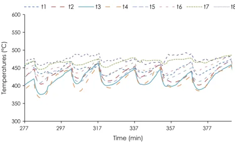
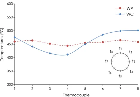
Information on the physical structure of the oxidation zone (OZ) during the experiments was obtained thanks to the measurements recorded by the eight thermocouples installed around the wall of the reactor at the same elevation as the OZ (i.e. 30 cm from the
bot-tom grate).Figs. 10 and 11show changes in the temperature over
time during experiments in continuous mode, for wood chips and wood pellets. The temperatures fluctuate because the OZ oscillates downward when extracting the char from the bottom of the reac-tor and upward due to its propagation towards virgin wood. The repeatability of the measurements throughout the different cycles of the experiments remained good. It is noteworthy that tempera-tures around the OZ were much more dispersed in the case of
wood chips, where temperature differences of more than 100!C
were measured. These results are confirmed by Fig. 12, which
shows wall temperatures around the OZ at a fixed time (357 min for wood chips and 285 min for wood pellets) after char was
extracted, when the temperatures were at their lowest.Figs. 10–
12clearly show that with wood chips the oxidation zone was not
horizontal, whereas with wood pellets, the differences between the wall temperatures were very slight, meaning the oxidation zone was horizontal. A probable explanation of this difference in behavior is that solid flow is more uniform with wood pellets and is comparable with a piston flow due to high gravity force. The heterogeneous size and shape of wood chip particles results in a non-homogeneous flow of the reacting particle in the reactor, explaining why the shape of the OZ in a continuous operating mode is not flat. This is also why maintaining the oxidation zone at a fixed elevation in the reactor, based on bed temperature mea-surements, as mentioned previously, is more difficult with wood chips than with wood pellets.
300 350 400 450 500 550 600 277 297 317 337 357 377 Temperatures (°C) Time (min) t1 t2 t3 t4 t5 t6 t7 t8
Fig. 10. Changes in temperatures around a section near the oxidation zone during the experiment with wood chips.
300 350 400 450 500 550 600 212 232 252 272 292 312 332 352 Temperature (° C) Time (mins) t1 t2 t3 t4 t5 t6 t7 t8
A new insight is proposed here to better interpret the observed air: wood mass ratios. In the literature, the air: wood mass ratio in a batch reactor in an oxygen limited zone is always higher than 1.5
[12–17]. In some experiments we conducted in batch mode (not
shown in this paper) we observed ratios higher than 1.3. In contin-uous mode, this ratio was around 0.7. This means that the oxida-tion zone velocity is much higher in the continuous mode studied here than in batch modes. The explanation we propose is that in the batch mode studies, the reactor is initially at ambient temperature, and when OZ propagates inside a cold reactor, the transfer of heat from the OZ to the reactor wall is very intense, which slows down the propagation of the oxidation zone. In con-tinuous mode, once the steady state regime is reached, the OZ remains in a preheated reactor zone, and the transfer of heat between the OZ and the wall is very low.
4. Conclusion
The aim of this work was to investigate the behavior of oxida-tive autothermal pyrolysis of wood in a downdraft continuous fixed bed reactor. This mode of operation consists in maintaining a stable oxidation zone (OZ) inside the bed. The zone tends to prop-agate upward - opposed to wood and air flows - but can be kept at a fixed elevation by removing char at the bottom.
Such operating conditions were achieved using temperature measurement as an indicator of the elevation of the front. In a 20 cm I.D. insulated reactor, the resulting air: wood mass ratio of 0.7 was measured using an air flux in the range of 0.014–
0.029 kg m"2s"1. The propagation of the oxidation zone consumes
about 12% of the stoichiometric combustion air to provide energy for the autothermal pyrolysis process.
In stable continuous fixed bed conditions, oxidative pyrolysis of woodchips produced about 17% char, 10% tars, 25% water, and 55% permanent gases. This distribution differed slightly from that obtained with wood pellets, except for water yields. Air flux was shown to mainly affect char yield: a decrease of about 20% was measured when the air flux was doubled.
Overall, the air: wood ratio measured in our continuous operat-ing mode was only slightly influenced by wood bulk density and air flux. But it is noteworthy that this ratio is 2–4 times lower than the ratios reported in batch mode experiments. In our opinion, this
underlines the importance of heat losses in the smoldering process as well as the advantage of the continuous pyrolysis process to optimize thermal efficiency.
Wood density was shown to significantly influence the velocity and the shape of the oxidation zone. Velocity was inversely propor-tional to the wood bulk density. In a bed made from dense wood pellets, the oxidation zone is almost flat and horizontal, whereas when wood chips are used, it is somewhat inclined. These results are linked to the impact of wood properties on particles flowing along the fixed bed, i.e. ‘‘piston” type for dense wood pellets, less homogenous and faster for wood chips.
This work was carried out using two wood samples both with about 9% moisture content. Future work will focus on the impact of this parameter on the behavior of the front.
Acknowledgements
This research was partly funded by CIRAD (French agricultural research center) and Mines-Nantes (French graduated school of engineering), in collaboration with Mines-Albi.
References
[1]Antal MJ, Grønli M. The art, science, and technology of charcoal production. Ind. Eng. Chem. Res. 2003;42(8):1619–40.
[2]Handbook biomass gasification. Biomass technology group (BTG). The Netherland: Knoef HAM; 2012.
[3]Anca-Couce A, Zobel N, Berger A, Behrendt F. Smouldering of pine wood: kinetics and reaction heats. Combust Flame 2012;159(4):1708–19. [4]de Souza Costa F, Sandberg D. Mathematical model of a smoldering log.
Combust Flame 2004;139(3):227–38.
[5]Carvalho ER, Gurgel Veras CA, CarvalhoJr JA. Experimental investigation of smouldering in biomass. Biomass Bioenergy 2002;22(4):283–94.
[6]Ohlemiller TJ. Modeling of smoldering combustion propagation. Prog Energy Combust Sci 1985;11(4):277–310.
[7]Nolter MA, Vice DH. Looking back at the Centralia coal fire: a synopsis of its present status. Int J Coal Geol 2004;59(1–2):99–106.
[8]Martins MF, Salvador S, Thovert J-F, Debenest G. Co-current combustion of oil shale – Part 2: Structure of the combustion front. Fuel 2010;89(1):133–43. [9]Yang YB, Phan AN, Ryu C, Sharifi V, Swithenbank J. Mathematical modelling of
slow pyrolysis of segregated solid wastes in a packed-bed pyrolyser. Fuel 2007;86(1–2):169–80.
[10]Yang YB, Sharifi VN, Swithenbank J. Effect of air flow rate and fuel moisture on the burning behaviours of biomass and simulated municipal solid wastes in packed beds. Fuel 2004;83(11–12):1553–62.
[11]Rostami A, Murthy J, Hajaligol M. Modeling of a smoldering cigarette. J Anal Appl Pyrolysis Jan. 2003;66(1–2):281–301.
300 350 400 450 500 550 600 1 2 3 4 5 6 7 8 Temperatures (°C) Thermocouple Gran. PF
WP
WC
[12]Mahapatra S, Dasappa S. Experiments and analysis of propagation front under gasification regimes in a packed bed. Fuel Process Technol 2014;121:83–90. [13]Porteiro J, Patiño D, Collazo J, Granada E, Moran J, Miguez JL. Experimental
analysis of the ignition front propagation of several biomass fuels in a fixed-bed combustor. Fuel 2010;89(1):26–35.
[14]Porteiro J, Patiño D, Miguez JL, Granada E, Moran J, Collazo J. Study of the reaction front thickness in a counter-current fixed-bed combustor of a pelletised biomass. Combust Flame 2012;159(3):1296–302.
[15]Milhé M, van de Steene L, Haube M, Commandré J-M, Fassinou W-F, Flamant G. Autothermal and allothermal pyrolysis in a continuous fixed bed reactor. J Anal Appl Pyrolysis 2013;103:102–11.
[16]Ryu C, Yang YB, Khor A, Yates NE, Sharifi VN, Swithenbank J. Effect of fuel properties on biomass combustion: Part I. Experiments—fuel type, equivalence ratio and particle size. Fuel 2006;85(7–8):1039–46.
[17]Shin D, Choi S. The combustion of simulated waste particles in a fixed bed. Combust Flame 2000;121(1–2):167–80.
[18]Saastamoinen JJ, Taipale R, Horttanainen M, Sarkomaa P. Propagation of the ignition front in beds of wood particles. Combust Flame 2000;123(1– 2):214–26.
[19]Teixeira G. Gazéification de charbon de granules de bois : comportement thermochimique et mécanique d’un lit fixe continu. Toulouse, INPT; 2012. [20]Mermoud F. Gazéification de charbon de bois à la vapeur d’eau : de la particule
isolée au lit fixe continu. Toulouse, INPT; 2006.
[21]Van de steene L, Tagutchou JP, Escudero Sanz FJ, Salvador S. Gasification of woodchip particles: experimental and numerical study of char–H2O, char– CO2, and char–O2 reactions. Chem Eng Sci 2011;66(20):4499–509. [22]Anis S, Zainal ZA. Tar reduction in biomass producer gas via mechanical,
catalytic and thermal methods: a review. Renew Sustain Energy Rev 2011;15(5):2355–77.
[23]Devi L, Ptasinski KJ, Janssen FJJG, van Paasen SVB, Bergman PCA, Kiel JHA. Catalytic decomposition of biomass tars: use of dolomite and untreated olivine. Renew Energy 2005;30(4):565–87.
[24]Devi L, Ptasinski KJ, Janssen FJJG. A review of the primary measures for tar elimination in biomass gasification processes. Biomass Bioenergy 2003;24 (2):125–40.
[25]Han J, Kim H. The reduction and control technology of tar during biomass gasification/pyrolysis: an overview. Renew Sustain Energy Rev 2008;12 (2):397–416.
[26]Li C, Suzuki K. Tar property, analysis, reforming mechanism and model for biomass gasification—an overview. Renew Sustain Energy Rev 2009;13 (3):594–604.
[27]Elliott DC. Relation of reaction time and temperature to chemical composition of pyrolysis oils. Pyrolysis oils from biomass. American Chemical Society; 1988. p. 55–65. vol. 376, 0 vols.
[28]Dufour A, Girods P, Masson E, Normand S, Rogaume Y, Zoulalian A. Comparison of two methods of measuring wood pyrolysis tar. J Chromatogr A 2007;1164 (1–2):240–7.
[29]Boroson ML, Howard JB, Longwell JP, Peters WA. Product yields and kinetics from the vapor phase cracking of wood pyrolysis tars. AIChE J Jan. 1989;35 (1):120–8.
[30] Baumlin S, Broust F, Ferrer M, Meunier N, Marty E, Lédé J. The continuous self stirred tank reactor: measurement of the cracking kinetics of biomass pyrolysis vapours. Chem Eng Sci Jan. 2005;60(1):41–55.
[31]Anca-Couce A. Reaction mechanisms and multi-scale modelling of lignocellulosic biomass pyrolysis. Prog Energy Combust Sci 2016;53:41–79.
![Fig. 8. The different regimes of smoldering relative to the air: wood ratio [13].](https://thumb-eu.123doks.com/thumbv2/123doknet/14021385.457394/8.892.203.677.876.1141/fig-different-regimes-smoldering-relative-air-wood-ratio.webp)