Blood Oxygenation by Photocatalysis
byARCHIVES
Tania UllahS.B. Mechanical Engineering
Massachusetts Institute of Technology, 2007
SUBMITTED TO THE DEPARTMENT OF MECHANICAL ENGINEERING IN PARTIAL FULFILLMENT OF THE REQUIREMENTS FOR THE DEGREE OF
MASTER OF SCIENCE IN MECHANICAL ENGINEERING AT THE
MASSACHUSETTS INSTITUTE OF TECHNOLOGY MASSACHUSETTS INSTITTE
OF TECHNOLOGY
JUNE 2009
JUN
16 2009
© 2009 Massachusetts Institute of Technology.All rights reserved
LIBRARIES
Signature of Author:
SDepartment
of Mechanical EngineeringMay 8, 2009
Certified by:
Todd Th rsen Associate Professor of Mechanical En eering s r Supervisor
Certified by:
Richard Gilbert Visiting Scientist, De ~p ent of Mecbanjeal Engineering
. ,' - -A1/fo heM pervisor
Accepted by:
_-David Hardt Graduate Officer, Department of Mechanical Engineering
Blood Oxygenation by Photocatalysis
by
Tania Ullah
Submitted to the Department of Mechanical Engineering on May 8, 2009 in Partial Fulfillment of the Requirements for the Degree of Master of Science in Mechanical
Engineering
Abstract
Recent statistics provided by the American Lung Association assert that over 400,000 Americans die every year from lung disorders and more than 35 million are now living with symptoms of lung disease. Mortality rates of heart disease and certain cancers have declined in recent years partly due to improvements in diagnostic testing and the development of targeted medical technologies. Such improvements have not translated over to the treatment of lung disease and lung cancer. The goal of the artificial respiration project is to create a self-contained, mobile oxygen supply that is suitable for implantation and that can potentially replace acute or chronically disabled lungs.
A novel microfluidic device for the oxygenation of whole blood has been developed. The device couples a semiconductor, titanium dioxide (TiO2), thin film that generates oxygen through photocatalysis with a microfluidic network that facilitates diffusion of the dissolved oxygen to red blood cells. While true pulmonary respiration relies on passive diffusion of oxygen gas from the environment to the blood, the proposed device differs in that it generates oxygen directly from the water in blood plasma. This thesis focuses on the work done to fabricate and characterize the semiconductor photocatalyst, design the integrated microfluidic chip, and validate its capacity to oxygenate blood in real-time.
Blood oxygenation experiments show that the microfluidic device exhibiting the best performance produced 4.06 mL of oxygen per 100 mL of blood, nearly two-thirds of the oxygen transferred in the lung. The flux of oxygen at the photocatalyst surface was 1.11 x
10-3 mmol 02/ (cm2 - min). The 02 flux is nearly two orders of magnitude larger than that
of any other fluidic device for blood oxygenation to date. The results from the proof-of-concept microfluidic device are promising and are a step towards the realization of a photocatalytic artificial lung.
Thesis supervisor: Todd Thorsen
There are many friends and colleagues I would like to thank for helping me throughout my years here at MIT. The Institute has exposed me to the most productive, brilliant, inspiring, creative and fun-loving individuals I know, and for that I am very grateful.
I would first like to thank my thesis advisors, Todd Thorsen and Richard Gilbert, for their invaluable support as I explored the many directions in which this project took me and attempted to find my niche in a field entirely new to me. I am especially appreciative of the patience you two exhibited as I encountered the inevitable stumbling blocks of experimental research.
I also extend my thanks to the other members of the Thorsen Group. Marco Rasponi, you were instrumental in defining the direction the artificial respiration project would take and taught me a great deal about how to conduct quality research. Chien Chih Huang and Raymond Lam, you two were great sources of information and help when I felt as though I was really stuck with my work. Sumeet Kumar, thanks for your friendship and advice, and the fun times we had in the lab.
I cannot forget to thank the members of Professor Caroline Ross's group who answered all my questions about metal oxide film deposition, Kurt Broderick of the Microsystems Technology Laboratories staff who became my fab guru, and the countless other brains I have picked over the last two years. It is amazing how much one can learn from one's colleagues.
Last, but certainly not least, I would like to thank my dear parents and siblings who have supported me throughout my journey at MIT. I really could not have done this without you!
Abstract ... 3
Acknowledgements ... 5
C ontents ... 7
List of Tables and Figures...9
1. Introduction ... ... 11
1.1 Overview of the Microfluidic Device for Photocatalytic Blood Oxygenation ... 13 1.2 Organization...15 2. Background... 17 2.1 Respiration... 17 2.1.1 Pulmonary Respiration ...17 2.1.2 Blood Oxygenation ... 21 2.2 Photocatalysis... 23 2.2.1 Semiconductor Photocatalysis ... 24 2.2.2 Electron-hole Recombination... 26 2.2.3 Photoelectrochemical Cells...28 2.3 Microfluidics ... 30
3. Film Fabrication and Characterization ... 33
3.1 Sol-gel...34
3.1.1 Experiments... ... 35
3.1.2 Results and discussion ... 37
3.2 Reactive D.C. magnetron sputtering ... 41
3.2.1 Experiments ... 42
3.2.2 Results and discussion ... 43
3.3 Conclusions ... 47
4. Microfluidic Device Design and Experimentation... ... 49
4.1 Photocatalytic cell (PC) design and fabrication ... 50
4.1.1 ITO/TiO2 thin film deposition ... 52
4.2 Testing oxidative capacity ... 57
4.2.1 Bias voltage experiments ... 58
4.2.2 Electrolysis experiments ... 62
4.3 Blood oxygenation ... 64
4.3.1 Blood oxygenation experiments... 66
4.3.2 Experimental observations and issues ... 69
4.3.3 UV light intensity experiments... 71
4.3.4 Film thickness experiments... 73
4.4 Conclusions... 75
5. Summary and Future work...77
A. Microfluidic device fabrication ... 81
A.1 ITO/TiO2 thin film deposition... ... 81
A.2 Electrode deposition... ... 83
A.3 Channel fabrication... ... ... 83
Figure 1.1: Age-adjusted Cancer Death Rates for Males in US, 1930-2004 ...12
Figure 2.1: Electron micrograph showing a pulmonary capillary in the alveolar wall...20
Figure 2.2: 02 dissociation curve...22
Figure 2.3: Illustration of the major processes occurring on a semiconductor particle following electronic excitation... ... 25
Figure 2.4: Schematic illustration of decomposition of acetic acid ... 27
Figure 2.5: Electrochemical cell employing TiO2 as an anode ... 29
Table 3.1: Sol-gel sample matrix, ratios of TIP:AcA:IPA:H20... 36
Figure 3.1: XRD patterns of sol-gel samples made in ratios 1:2:5:1 and 1:3:5:1 ... 38
Figure 3.2: XRD patterns of sol-gel samples 1:2:9:1, 1:2:10:1, 1:2:12:1 and 1:2:14:1 ....40
Figure 3.3: XRD patterns of sol-gel samples 1:3:9:1, 1:3:10:1, 1:3:12:1 and 1:3:14:1....41
Table 3.2: Test array for film deposition experiments ... 43
Figure 3.4: XRD patterns of sputtered samples of varying deposition pressure ... 44
Figure 3.5: XRD patterns of sputtered samples of varying sample temperature...46
Figure 3.6: XRD patterns of sputtered samples of varying oxygen content...47
Figure 4.1: Schematic and photo of assembled device ... 51
Figure 4.2: Schematic of patterned ITO and TiO2 thin films ... 52
Figure 4.3: Schematic view of fabrication steps to assemble the microfluidic device... 56
Figure 4.4: The molecular structure of methylene blue ... ... ... 58
Figure 4.5: Photo of experimental set-up with UV optical fiber ... 59
Figure 4.6: Effect of bias voltage on methylene blue degradation... 60
Table 4.1: Rate constants for methylene blue degradation under various bias voltages... 62
Figure 4.7: Effect of electrolysis on methylene blue degradation ... 63
Figure 4.8: Increase in blood oxygen content for various initial 02 saturation ... 67
Table 4.2: Comparison of oxygen flux from different PC designs ... 68
Figure 4.9: UV light guide ... ... 70
Figure 4.10: Photo of experimental set-up with UV LED...71
Chapter 1
Introduction
Every year, almost 400,000 Americans die from lung disease, and it is the number three killer in the country (behind heart disease and cancer), responsible for 1 in 6 deaths.' The lung disease death rate has been increasing over the last decade, while death rates due to other leading causes of death have been declining. Asthma and chronic obstructive pulmonary disorder (COPD) are the most common obstructive lung diseases, with more than 12 million people currently diagnosed with COPD and another 12 million who likely have the disease without knowing it.2 Additionally, the National Heart Lung and Blood Institute estimates that about 190,000 Americans are affected annually by acute
respiratory distress syndrome (ARDS) - a life-threatening condition in which normal gas exchange is compromised by severe buildup of fluid in both lungs.' Furthermore, lung disease and various forms of respiratory problems constitute one leading cause of death of babies under the age of one. These disheartening statistics, as well as the fact that lung disease costs the US economy approximately $154 billion in direct and in-direct health-care expenditures,1 provides us the incentive to develop solutions to address chronic and acute respiratory illnesses.
ix 1 PUlr- _...l
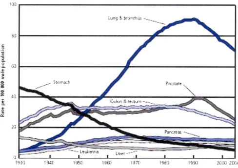
Figure 1.1: Age-adjusted Cancer Death Rates for Males in the US, 1930-2004. This
graph, reproduced from the American Cancer Society 2008 Cancer Facts & Figures Report, shows that cancer of the lung and bronchus remains one of the leading causes of cancer death.
Mortality rates of heart disease and certain cancers have declined in recent years partly due to improvements in diagnostic testing and the development of targeted medical technologies. Such improvements have not translated over to the treatment of lung disease and lung cancer. Current treatments include medication (e.g. corticosteroids to reduce inflammation in the airways and antibiotics to treat bacterial infections),
mechanical ventilation (e.g. neattive and positive pressure devices that increase the amount of air moving into the lungs), oxygen therapy (e.g. extracorporeal membrane oxygenation (ECMO)), and surgery (e.g. lung transplantation and lung reduction surgery to excise diseased tissue). Non-surgical treatments, although they provide brief respite from the symptoms of respiratory disease, are not sufficient standards of care for chronic sufferers. For example, in ECMO, a treatment technique in which cannulae are inserted into the large vessels in the body and blood is pumped through gas-permeable
membranes in order to facilitate oxygen and carbon dioxide exchange, there is a
significant risk to the patient of thrombosis (blood clotting), infection, and bleeding under anticoagulant medication.3Other downsides to ECMO, which has been used consistently
since the early 1970s, include the requirement of a large pumping power to flow the blood through the machine, biofouling on the machine's membranes due to protein and platelet adhesion, and high cost of operation.4
Select patients with end-stage lung disease, for whom conventional therapies will not improve life expectancy or alleviate symptoms, lung transplantation remains the only option. However, according to the Scientific Registry of Transplant Recipients, 14% of those on the national waitlist between 2007 and 2008 died before they could receive a lung. For those who received a graft, the survival rate 3 years after implantation
plummeted by 30%.5 Even in the case where lung transplant is successful, patients must take autoimmune drugs for the rest of their life.6 The transplanted lung is "foreign" to the
body and, as a result, there is the possibility of rejection. Patients who receive new lungs must take the autoimmune drugs to suppress the body's natural rejection process.
1.1 Overview of the microfluidic device for
photocatalytic blood oxygenation
This thesis discusses a novel approach to developing a device to oxygenate blood - an "artificial lung". As discussed earlier, current treatments for lung disease are not completely effective, nor are they sustainable in the long term. The goal of the artificial respiration project is to create a self-contained, mobile oxygen supply that is suitable for implantation and that can potentially replace acute or chronically disabled lungs. The device that is presented in this thesis has the potential of sustaining human respiration because no refillable tank of gas or pumping power is involved. The oxygenation of the blood works on the following principle: oxygen is generated in the fluid stream directly from the dissociation of water in the blood plasma.
The device couples a semiconductor titanium dioxide (TiO2) thin film that generates
oxygen through photocatalysis with a microfluidic network that facilitates diffusion of the dissolved oxygen to red blood cells. When the thin film semiconductor is irradiated with ultraviolet (UV) light (of wavelength X = 365 nm), electron vacancies, or holes, are
generated and migrate toward the surface to provide sites for oxidation. Blood flowing in the PDMS microchannel is in direct contact with the TiO2 photocatalyst and the water
present in blood is oxidized to aqueous oxygen, ready to bind to red blood cell hemoglobin. In this manner, the proposed implantable device will be capable of saturating flowing blood with oxygen in real-time. Real-time oxygenation means that with one pass through the device, blood can go from venous levels of oxygen saturation to arterial levels.
As this is a project that resides at the intersection of multiple disciplines, research in artificial respiration technology can lead in several directions. The breakdown of the areas in which we are looking to make developments are as follows:
1) Optimizing the function of the thin film semiconductor photocatalyst
The generation of oxygen from photocatalytic water dissociation needs to be
sufficient in order to sustain cellular respiration in the tissues of the body. Our goal is to maximize the oxidative potential of the photocatalyst by optimizing thin film processing.
2) Microfluidic channel scaling and geometry to improve mass transport
Previous studies have investigated microcapillary branching in channels molded in polydimethylsiloxane (PDMS), mimicking the architecture of pulmonary capillaries. The blood flow in these designs, however, is limited due to high rates of hemolysis and intraluminal clotting.4'7
3) Optics module to efficiently deliver UV light to semiconductor
The semiconductor is activated by light in a narrow band within the UV range (with a peak activation at X = 365 nm) and there is a maximum flux of photons needed to
generate electron holes continuously. An optics module needs to be developed in order to minimize the power required to operate the device and to efficiently relay the light to where it is needed (the photocatalyst) and shield the light from areas where it can potentially cause damage.
4) Integrated design of all components
The work discussed in this thesis encompasses goals (1) and (4). Experiments with our design have shown that (a) we can produce a constant flux of 02 from the photocatalyst over time thus allowing steady-state operation and (b) blood can be fully oxygenated in real time, although only at slow flow rates at present.
1.2 Organization
The thesis will be organized as follows:
Chapter 2 provides relevant background in order to understand how blood oxygenation occurs in vivo and how photocatalysts are employed to produce oxygen, as it relates to the design goals of the microfluidic device for artificial respiration.
Chapter 3 discusses the fabrication of the thin film photocatalyst and its characterization.
The goal is to develop a deposition protocol to produce a highly active film.
Chapter 4 proposes a design for a device that incorporates a highly active thin film
photocatalyst into a microfluidic chip, details its fabrication procedure and validates device function.
Chapter 5 presents a brief summary of the thesis, discusses ongoing work that is being
Chapter 2
Background
The microfluidic device for artificial respiration is the result of a complex integration of technologies from various fields. For the proper design of a microfluidic device, the requisite knowledge of biology, biochemistry, materials science, and micro- and nano-fabrication are necessary. For this project, in particular, a brief review of respiration, photocatalysis, and microfluidics is relevant.
2.1 Respiration
Respiration can be divided into two phases: internal and external. Internal, or cellular respiration, is the set of metabolic reactions that takes place in the cells once it has acquired dissolved oxygen gas to convert carbohydrates into biochemical energy. The mechanisms of cellular respiration are well known and are not studied in this work. External, or pulmonary, respiration is of interest at present because most patients of lung
disease suffer when pulmonary respiration is affected. The following is a brief, yet critical, overview of the fundamentals of respiration as it pertains to the issues addressed by the device for artificial respiration.
2.1.1
Pulmonary respiration
The function of the lungs is to facilitate gas exchange with the environment-oxygen to venous blood and carbon dioxide out of the body. Although the lungs have other
functions (metabolizing compounds and filtering unwanted materials from blood circulation, for example), the main purpose of the organ is to get oxygen to the blood
where it can be taken to the tissues of the body for cellular respiration and release the byproduct, carbon dioxide.
The exchange of oxygen and carbon dioxide relies on a pressure differential and simple gas diffusion through thin membranes. When one inspires, the volume of the thoracic cavity increases because of the displacement of the diaphragm and the rising of the ribs. The pressure in the lung's internal cavity decreases, inducing a rush of air into the
airways. The average person breathes in about 4 liters of air into her lungs per minute and the heart pumps approximately 5 liters of blood per minute through the pulmonary
cavity.8 The large volume of fluid, both air and blood, must efficiently undergo an exchange of gases in a short period of time. The unique structure of the lung allows for efficient and rapid oxygen and carbon dioxide exchange.
According to Fick's law of diffusion, the flux of gas transport through a tissue is
proportional to surface area and inversely proportional to the thickness of the membranes. The membranes constituting the blood-gas barrier in lungs are very thin (dimensions as small as 0.3 tm in certain areas) and the barrier has a total surface area between 50 and 100 square meters.9 The average lung, however, only has about 10% solid tissue. Three-hundred million tiny air sacs, called alveoli, are responsible for the prodigious surface area and the total volume of the alveoli amounts to 4 liters.8'9 To provide some
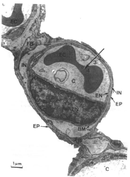
perspective, a sphere of the same volume would have a surface area of only 1/100th of a square meter. The alveoli are surrounded by webs of tiny capillaries measuring 5-10 pm in diameter. Since erythrocytes are 6-8 jtm in diameter, they enter the capillaries in single file, allowing for a direct path for oxygen diffusion to the cells. Refer to Figure 2.1, an electron micrograph showing a pulmonary capillary (C) that resides in the thin blood-gas barrier. The arrow indicates the diffusion path from the alveoli (the white void) to the erythrocyte (EC), or red blood cell.
As is evident from the micrograph, the membrane through which oxygen must diffuse can be as thin as a 0.3 im. The diffusion coefficient, D, of a molecule is proportional to
the gas solubility, Sol, and inversely proportion to the square of the molecular weight, MW:
Sol Doc
The time required for diffusion scales with the square of the membrane thickness, L, and the inverse of the diffusion constant:
L2
D
Abnormalities common to lung disease often result in the mucosal thickening of the blood-gas barrier, essentially increasing the value of L, thus impeding the diffusion of gases across it. As mentioned previously, chronic sufferers of lung disease often have infections that thicken the layer of viscous fluid in their lungs, making it very difficult for them to breathe.
Figure 2.1: Electron micrograph showing a pulmonary capillary in the alveolar wall.
2.1.2
Blood oxygenation
The structure and function of hemoglobin and myoglobin have been investigated
thoroughly by biochemists over the last five decades. They were the first proteins whose three-dimensional structures were determined' "11 and, as a result, the reversible binding
of a protein to ligand is now very well understood. Hemoglobin is a protein residing in red blood cells containing four identical subunits that contains an iron-porphyrin heme
group and functions in the transport of oxygen. Myoglobin, although structurally similar to a single subunit of hemoglobin, is the oxygen-storing protein in muscles.
Oxygen has a low solubility in aqueous solutions and cannot be carried to the tissues of the body in sufficient amounts simply by dissolution in blood serum. The solubility of oxygen in blood is only 0.0031 mL 02/100 mL blood/mm Hg. Small organisms have found it possible to rely solely on the diffusion of oxygen through membranes, but that alone cannot sustain larger multicellular organisms as diffusion is ineffective over distances greater than a few millimeters. Birds and mammals employ hemoglobin by exploiting the strong tendency of oxygen to bind to certain transition metals, like iron and copper.12 The protein prosthetic group, heme, consists of an organic ring, protoporphyrin, that has a single iron atom in the ferrous state (Fe2+) at its center. Fe2+ is capable of binding oxygen reversibly and more than 90% of the oxygen in blood serum is that which is bound to the hemoglobin.
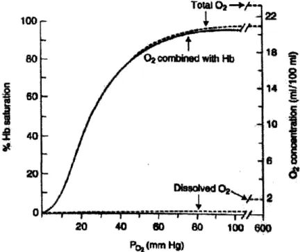
The figure below shows the sigmoidal oxygen affinity curve for hemoglobin. The hemoglobin in blood must bind oxygen efficiently in the lungs, while releasing the oxygen (have decreased affinity for binding) in the tissues of the body. Allosteric
proteins, such as hemoglobin, are capable of having variable affinities to ligands because the binding of a ligand to one site causes conformational changes that affect binding to another site. In the case of hemoglobin, there are four binding sites for 02 and, as more oxygen molecules bind to it, the protein transitions from a low-affinity state to a high-affinity. Therefore, as oxygen binds to hemoglobin in the lungs where the partial pressure, pO2, is about 13.3 kPa, its affinity increases and more oxygen binds.
oxygen releases itself from hemoglobin and the binding affinity decreases.12 Figure 2.2
also shows that approximately 10% of the oxygen concentration in blood is dissolved in the plasma, while the other 90% is combined with hemoglobin.
100
I
14 •1 2E 20 40 60 8O 100 ~m0 P, (mmn Hg)Figure 2.2: 02 dissociation curve. The solid line is for pH = 7.4, pCO2 = 40mm Hg, and temperature = 37°C. The dotted line is the oxygen concentration in 100 mL blood.
[Reproduced from West, 2000]
Normal erythrocytes (red blood cells) are small biconcave disks (about 6 to 9 ,m in diameter) that are vestigial cells, unable to reproduce and survive for more than 120 days.10 Their sole function is to carry hemoglobin. In arterial blood, hemoglobin is 96% saturated with oxygen and venous blood is about 64% saturated. Therefore, about every 100 mL of blood flowing from the lungs, throughout the body, and then back again releases about 6.5 mL 02 in the process.9 This serves as a benchmark for our
respiration is to achieve enough oxygen yield from the photocatalytic reaction to sustain cellular respiration in the body.
2.2
Photocatalysis
The breakthrough work of Fujishima and Honda in 1972,13 in which they achieved ultraviolet light-induced water cleavage with the use of titanium dioxide (TiO2) in an
electrochemical cell, has drawn considerable attention in recent years to the "acceleration of a photoreaction by the presence of a catalyst"' 4 or photocatalysis. The possibility of
solar energy conversion by semiconductors or sensitizers is of increasing interest because of the current effort to create renewable energy sources to replace the use of fossil fuels. Exhaustion of natural energy sources and environmental pollution has almost necessitated these technological efforts. The amount of solar light impinging on the earth's surface is more than 1024 J/year, 104 times that of the world's energy consumption.15,16
Consequently, harnessing solar energy in sustainable and environmentally-friendly processes has become one major effort to decrease the global dependence on fossil fuels.
The need for efficient production of fuels from inexpensive materials and with minimum waste generation has been the motivator for many research projects in energy. An example of simple, and highly desirable, reactions is the oxidation reaction of water into H2 and 02 and the reduction of CO2 into methanol driven by light. The effect of light in
these cases is to create electron-hole pairs in catalysts that, like the charge separation in a battery, provide the driving energy for reactions to take place. The analogous model often used for these energy conversion systems is biological photosynthesis.
During the process of photosynthesis, plants and certain species of bacteria capture energy from sunlight and produce useable fuels that help them grow. In this process, CO2
is reduced to sugar and carbohydrates in a rather complex set of reactions: pigments absorb energy from sunlight, that energy oxidizes water to produce oxygen, and the electrons from the oxidation reaction contribute to the formation of carbohydrates. The
fundamental aspect of the energy conversion process is the removal and then separation of the electrons from their source, H20. The separation of charges is accomplished by the
presence of very thin lipid membranes in the organelles of plant cells through a series of intermediate redox reactions involving proteins with metal complexes. Photocatalysis essentially replicates this first phase of the photochemical solar energy conversion of photosynthesis - light induced water splitting and charge separation - without carrying out the dark reactions that produce carbohydrates from CO2. Photosynthesis is the most
efficient and successful solar conversion system available, and thus serves as an ideal model for photocatalysis.
2.2.1
Semiconductor photocatalysis
Photocatalysts are used to induce redox reactions because solar energy alone cannot excite electrons of simple molecules to higher energy states. Semiconductors are uniquely positioned to be used as photocatalysts because of their electronic structure. By
definition, semiconductors are materials with an electrical conductivity between that of conductors and insulators. Upon illumination of these materials with light having energy greater than the bandgap energy, Ebs, electrons from the valence band elevate to higher energy levels leaving behind electron vacancies or "holes". Energy or current is carried
by electrons and holes, and the rate at which they move can be precisely tuned by
processes like doping, in which impurities are intentionally added to the bulk material to change its electronic structure. The photoexcitation of semiconductors is an effective means of initiating important and normally energetically unfavorable redox reactions.
The overall photocatalysis reaction in a semiconductor is as follows:
A + D semiconductor + light 2 Ebg A- + D+
where A is an electron acceptor and D is an electron donor.14,16 Upon excitation of light
or under the action of an electric field, the electrons and holes generated move in opposite
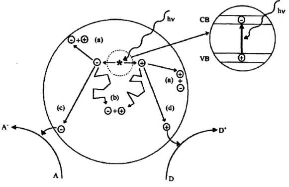
directions, either further into the bulk or to the surface of the photocatalyst, where an electron acceptor can be reduced (refer to Figure 2.3, reaction (c)) and where a donor can be oxidized (Figure 2.3, reaction (d)). Otherwise, recombination of the electron-hole pairs can occur within the bulk, losing the opportunity for their use in any redox reactions. This is of significance because the recombination of electron-holes is a severe limitation in photocatalysis.
Figure 2.3: illustration of the major processes occurring on a semiconductor particle
following electronic excitation. Electron-hole recombination can occur at the surface (reaction (a)) or in the bulk (reaction (b)) of the semiconductor. At the surface of the particle, photogenerated electrons can reduce an electron acceptor A (reaction (c))
and photogenerated holes can oxidize an electron holes can oxidize an electron donor
2.2.2
Electron-hole recombination
It is often a challenge to predict the yield of the photocatalytic redox reactions. That is, it is difficult to determine the lifetime of the oxidized and reduced species that form after a semiconductor photocatalyst has been activated by light. Energy absorbed by the material results in the formation of electron-hole pairs but, if the pairs do not migrate far or
recombine (reactions (a) and (b) in Figure 2.3) before reaching the surface of the semiconductor, the energy is simply released as heat. Unlike the formation of the
electron-hole pairs, it is not easy to predict the recombination rate directly. Photocatalytic semiconductors have generally been found to have low quantum efficiency because the recombination of electron-holes shortly after they are generated predominates the photocatalytic activity.1 7 An ordinary semiconductor redox reaction has the efficiency of
about 30%, meaning that 70% of the electron-hole pairs that are generated recombine before any reaction takes place.16 Thus, for the design and proper function of a
semiconductor photocatalyst, recombination cannot be ignored.
Research in the field of semiconductor photocatalysis has focused on designing materials with high activity. It is well known that photocatalytic activity depends on the surface area and particle size of semiconductor powders, the material's crystal structure,14 and adjustment of their bulk properties.18 The reason these properties have a significant effect on photocatalytic activity is because they each serve to segregate electrons and holes and/or reduce the probability of recombination. As the particle size decreases, the
photocatalytic activity of a semiconductor increases due to the increase in surface area to bulk volume ratio. Consequently, redox reactions are induced readily because the
diffusion distance (and thus, probability of recombination) for photogenerated electron-hole pairs is minimized. For this reason, photocatalysts are often employed in powder form or, in some instances, as thin films with high surface roughness. As for crystal structure, it has been shown that high crystallinity has the effect of increasing
photocatalytic activity in metal oxide semiconductors.17'1 9,20 Many studies have shown
defects-assumed sites of electron-hole pair recombination.14.16 The importance of crystal structure will be elaborated upon in a later chapter.
Recently, doping of photocatalytic semiconductors, like TiO2, has been attempted to
manipulate bandgaps such that the materials are highly reactive under visible light.18,21 Although materials with changed bulk properties suffer from thermal instability and a possible increase of electron-hole recombination centers, it has also been shown that the photocatalytic activity of TiO2 is remarkably enhanced with the addition of small
amounts of noble metals.' 8 This is explained by the quick segregation of the electrons and holes, as the electrons are transferred to the metal particles. In the case of photo-induced splitting of water using platinum-loaded TiO2, for example, the holes are free to oxidize
water and the electrons on the Pt participate in H2 evolution. Recombination, in such a
case, is minimized. Figure 2.4 illustrates the decomposition of acetic acid using Pt-loaded TiO2 particles illuminated by UV light.
OH
c
)
*011
CHCHOOH *CH3 - C02
Figure 2.4: Schematic illustration of decomposition of acetic acid. [Reproduced from
The principle behind metal loading as a means of reducing the probability of electron-hole recombination can be extended to photoelectrochemical cells. In such cells, instead of adding metal particles to the bulk semiconductor directly, the photocatalyst is
connected via an external circuit to a metal electrode (usually made of platinum) through which electrons can be conducted. As presented in the following section, this system can be highly efficient in photocatalytic activity, with quantum yield reaching nearly 100% for some single-crystal semiconductor cells.16
2.2.3
Photoelectrochemical cells
The possibility of solar photocatalysis was first demonstrated in the late 1960s by Honda and Fujishima when an n-type TiO2 semiconductor connected to a platinum
counterelectrode was exposed to UV light (refer to Figure 2.5).6 When irradiated with light, current flowed from the platinum electrode to TiO2 through an external circuit. It was shown that oxygen evolution occurred at the TiO2 electrode and hydrogen gas
formed on the Pt electrode as per the following water-splitting reactions:
Excitation of TiO2 by light:
TiO2 + 2hv 2e- + 2h+ (Eq. 2.1)
At the TiO2 surface:
H20 + 2h+ -*0 2+ 2H+ (Eq. 2.2)
At the counter electrode:
2H + + 2e- --> H2 (Eq. 2.3)
The overall reaction is:
1
H2 0 + 2hv - 02 + H2 (Eq. 2.4)
In this preliminary photoelectrochemical cell, no external voltage was applied. When the semiconductor electrode is in contact with an electrolyte, as it is in Figure 2.5, charge
equilibrium takes place at the interface.16 A charge layer within the region close to the
semiconductor bends the electronic energy bands and creates a local electric field, driving photogenerated holes toward the surface of the semiconductor and electrons into the bulk material. In solution, the redox reactions occur readily on the surfaces of the electrodes because the action of the electric field efficiently drives electrons and holes in opposite directions.22
6
4 V 4
5
SLO
Figure 2.5: Electrochemical cell employing TiO2 as a photoanode. (1) n-type TiO2
semiconductor; (2) platinum counter electrode; (3) ionically conducting separator; (4) gas buret; (5) load resistance; (6) voltmeter. [Reproduced from Fujishima, 2000]
The presence of a counter electrode and electrolyte solution are essential for high yield of electron-hole pairs. As in the case of metal-loaded semiconductors, where small amounts of Pt, for example, are added to the bulk material, the counterelectrode serves as the site
for hydrogen evolution. The electrochemical cell used by Fujishima and Honda is a set-up that motivates the design of the photocatalytic cell for artificial respiration.
2.3 Microfluidics
Microfluidics is the manipulation of fluids in micrometer-sized channels, of volumes from 10-9 to 10-8 liters. The development of so-called labs-on-chips and micro
total-analysis systems (/TAS) has aided in the investigation of biological and chemical synthesis and analysis. The field of microfluidics has a wide range of applications, even those extending to optics and information technology. The scales on which these devices are designed lend themselves well to the fabrication techniques of semiconductor and integrated circuit technologies. Additionally, chips can be designed and fabricated rapidly, they are inexpensive and small, and they consume low volumes of samples and reagents. Therefore, microfluidics presents itself novel means of analysis and synthesis on the micro-scale.
The behavior of fluids on this scale can differ significantly from the behavior of "macrofluidics" because factors such as surface tension, energy dissipation, fluidic resistance and electrochemical interactions dictate phenomenon at the micro level. Microfluidics often studies these factors and how they can be exploited experimentally. In microfluidic devices, like the one that is discussed in this thesis, two things hold true: (i) the dimensionless Reynolds number is low and aqueous flow is laminar, not turbulent and (ii) diffusion plays an important role in mass flow because the feature dimensions are small.
In the case of the development of a device for artificial respiration, microfluidics plays an important role. To begin with, the oxygen being produced by the photocatalytic
semiconductor is essentially a flux of dissolved gas that comes only from the lower plane of the channel. In order for the oxygen to bind to the red blood cells that are flowing above the photocatalyst, it must diffuse through the height of the channel faster than it is
being advected by the flow. As mentioned earlier, that criterion is fulfilled if the P6clet number is low. Second, the channels that will be molded into the polymers of the ultimate microfluidic device design will have dimensions, geometry and branching similar to that of capillaries. Standard soft lithography techniques will make this a feasible endeavor.
Chapter 3
Film Fabrication and
Characterization
Since the 1960s, titanium dioxide has been the focus of research on photocatalysis and there have been many investigations into its various applications. TiO2 has been found to
be non-toxic and mechanically stable, can be fabricated at low-cost, and has a bandgap of approximately 3 eV, ideal for excitation by light in the ultraviolet range. Titanium
dioxide employed in aqueous form, in powders and as coatings on surfaces have great oxidative power. So far, the most active application of photocatalysis has been the photodegradation of organic compounds. TiO2 has been used as a coating for
self-cleaning and anti-microbial surfaces in office buildings and hospitals, and in water, air and wastewater treatment systems.23 Two years ago, an Italian company incorporated
TiO2 into cement to create smog-eating building materials for industrial and urban
settings.2 4 Titanium dioxide has also been used in anti-fogging coatings because of its superhydrophilicity when activated by UV light25 and has been employed as a means of killing malignant cancer cells.26 The application of most interest to this project is the use of the metal oxide semiconductor in solar cells for oxygen and hydrogen production by water splitting.
All of the uses of titanium dioxide in photocatalytic cell applications rely on its high activity once irradiated by UV light. It has been reported that amorphous TiO2 has
negligible activity indicating that crystallinity improves production of electron-holes and impedes recombination. Titanium dioxide exists in three crystal phases: rutile, anatase and brookite. Rutile is the most thermodynamically stable, and anatase exhibits the most photocatalytic activity, while brookite is the rarest and most inactive. Anatase and rutile both have titanium cations coordinated to six oxygen anions in an octahedron, but the
packing of the octahedra differ in the two crystals.27 The surface areas of anatase crystals tend to be greater than those of rutile as a result, and anatase films are slightly less dense.
The criteria for the titanium dioxide films that are to be employed in the microfluidic device for artificial respiration are as follows:
(1) High crystallinity: The concern is not so much the size of the grains, but the percent content of anatase versus other crystal phases. The presence of rutile will decrease the activity of the overall film. Therefore, our goal is to develop a deposition protocol to produce pure anatase thin films.
(2) Smooth films: High surface roughness or high porosity, although favorable for the
photocatalyzed splitting of water, is undesirable in biomedical applications because of the possibility of cell adhesion and proliferation within the semiconductor. Bio-fouling decreases the affective surface area of the photocatalyst and therefore ought to be minimized.
The overarching goal of the artificial respiration project is to supply oxygen to the blood stream in a closed system. In order produce enough oxygen to saturate red blood cell hemoglobin as it is in normal pulmonary function, the chief aim is to maximize the photocatalyst efficiency of oxygen formation. In the present chapter, the optimization and characterization of titanium dioxide thin films fabricated using two different methods
-the sol-gel method and reactive sputtering - have been explored.
3.1 Sol-gel
The sol-gel method is a wet-chemistry technique used primarily for the fabrication of metal oxides. The term refers to the first stage transformation of the "sol" or liquid-like material to a more solid-like "gel". The process involves the following steps: (1) formation of a sol containing an organometallic precursor, usually a metal alkoxide, in solution with alcohol and/or water; (2) aging and deposition of the sol on a substrate; (3) evaporation of the solvents, gel formation, and film solidification; and (4) heat treatment
for the pyrolysis of residual organics, and densification and crystallization of the film.28 The result is a thin film of metal oxide covalently bonded to the substrate. The reaction is
as follows:
Ti(OR)4 + (2 + x) H2 0 -* TiO2 x H2 0 (oxide nanoparticle attached to substrate) + 4ROH (Eq. 3.1)
The benefits to using the sol-gel method to deposit titanium dioxide films are that it is cost effective, involves simple process chemistry and equipment, and preparation conditions are tunable. Sol-gel has been used often in applications requiring coatings on large surfaces as a result.
3.1.1
Experiments
The sol was prepared using titanium (IV) isopropoxide (TIP) (Aldrich, 99.999%) metal precursor, acetylacetone (AcA) (Sigma-Aldrich, 99%), anhydrous isopropanol (IPA) (Sigma-Aldrich 99.5%) and de-ionized (DI) water. AcA served as a catalyst2 9, while the IPA and DI water was used to dissolve the metal precursor and affect the viscosity of the sol. Anhydrous IPA was used so as to be able to precisely control the molar ratio of water in solution. Measured quantities of each were added in the order indicated while the solution was mixed (with a magnetic mixer) on a balance. It was carried out in room temperature and in a nitrogen-infused glove box to minimize contaminants in the solution. The sol was stored in sealed vials in a dry, ventilated area overnight (up to 12 hours) before being spun on thoroughly cleaned three-inch silicon wafer substrates at
1000 rpm. The cleaning protocol entailed a piranha clean to remove oxide formation on the single crystal silicon, and rinse with methanol and isopropanol to increase
hydrophilicity. The films were dried in ambient air for one hour before annealing in a 450'C furnace for two hours. It was determined that the annealing time was sufficient to dehydrate the gel and initiate crystallization.
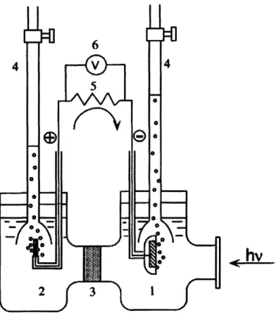
To develop the appropriate process protocol, the molar ratios of the chemicals were varied accordingly and tested: for every 1 part of TIP, acetylacetone was varied from 1 to 3 parts, isopropanol was added in 1, 5, 9, 10, 12, or 14 parts, and the DI water was added in 1 part. Below is the list of samples produced with their TIP: AcA: IPA: H20 ratios.
Table 3.1: Sol-gel sample matrix, ratios of TIP: AcA: IPA: H20
1:1:3:1 1:1:5:1 1:1:9:1
1:2:3:1 1:2:5:1 1:2:9:1 1:2:10:1 1:2:12:1 1:2:14:1
1:3:3:1 1:3:5:1 1:3:9:1 1:3:10:1 1:3:12:1 1:3:14:1
After annealing, the crystalline structures of the films were studied by glancing incidence X-ray diffraction (XRD). XRD is a technique used to non-destructively reveal
information about the crystallographic structure of a material. The material is bombarded with a parallel, monochromatic X-ray beam and the atoms in the lattice structure scatter the waves in diffraction patterns particular to the type of crystal being analyzed. When thin films are deposited on substrates, it becomes necessary to perform glancing
incidence (GI) XRD because the contribution to the diffraction pattern from the substrate overshadows that of the film. GIXRD entails shallow angles of incidence and a longer period of scattered wave detection as the signal detected is small for thin materials.
XRD measurements were carried out using a PANalytical X'Pert PRO Diffractometer with monochromated Cu Ka (X= 0.1540598) incident radiation. Because glancing incidence XRD was performed, the beam was incident at a shallow angle and the signal was collected from 200 to 60' 20. The scan was taken at a rate of 0.0089' (20) per second in order to obtain as many data points as possible from the thin film. The various
instrument parameters were programmed into the diffractometer using the X'Pert PRO Data Collector software. After each 1 hour 15 minute scan, the Data Collector outputted the diffraction pattern and it was compared to those of known, pure crystalline forms of TiO2(anatase, rutile and brookite) found in the XRD database. For all the patterns of the
samples tested, none exhibited any presence of brookite as expected and, therefore, the reference pattern for brookite was not included in the figures following.
3.1.2
Results and discussion
The figures below are diffraction patterns of representative samples with TIP: AcA: IPA: H20 ratios in Table 3.1. Not all the sol-gel solutions that were mixed successfully yielded
films. The samples that contained only one part AcA, ratios 1:1:3:1, 1:1:5:1, and 1:1:9:1, spun onto the Si wafers but after the sintering and annealing step, it was found that adhesion of the resulting film was very poor. The films were peeling off the substrate. A likely cause was that there was insufficient acetylacetone to catalyze the reaction in Eq. 3.1, the alkoxides were not cleaved and, as a result, no covalent bonds formed between the titanium dioxide and Si substrate. The samples with three parts IPA, ratios 1:2:3:1 and
1:3:3:1, were found to be too cracked after the annealing step to be tested with the XRD. It was determined that the cause was the fact that the films were too viscous (this was found to be true while the sol-gel was being spun onto the Si substrates) and the evaporation of solvents during the sintering step caused enough stress in the film to produce cracks. To circumvent this problem, sol-gel solutions with higher IPA content were produced.
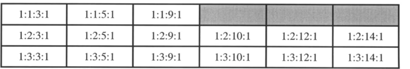
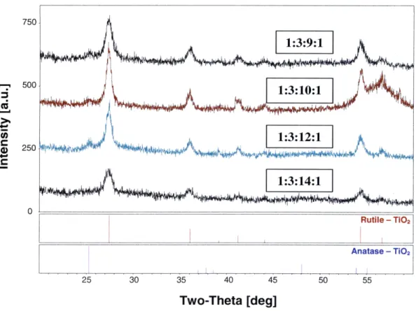
Figures 3.1, 3.2 and 3.3 shows the diffraction patterns of the films that were successfully produced using the sol-gel process and exhibited sufficient crystallization. In Figure 3.1, samples with 5 parts IPA, ratios 1:2:5:1 and 1:3:5:1 are compared to the peak locations and relative peak intensities of pure rutile and anatase below the diffraction patterns. For rutile TiO2, peak locations are at 20 = 27.40, 36.10, 39.20, 41.20, 44.10, 54.30 and 56.60 and for anatase, the peak locations are at 20 = 25.30, 36.90, 37.80, 38.60, 48.10, 53.90 and 55.1. As can be seen in the figure, the dominant crystal phase in 1:2:5:1 is rutile while there are only trace amounts of anatase (i.e. only the first, major anatase peak (101) appears in the diffraction pattern). It is also noted that the peaks have relatively low signal intensities indicating that there was not very much crystalline material in the film. Sample 1:3:5:1, on the other hand, exhibits anatase TiO2with trace amounts of rutile.
Both diffraction patterns show that there is a significant amount of amorphous TiO2 in
addition to the rutile and anatase crystal phases. This is indicated by the broad peak that occurs near 20 = 290. 500/Amorphous 4000
'
4000t 1:2:5:1 '-2 C 3000 Amorphous 2000 1:3:5:1 1000 0 Rutile - TIO2 Anatase - Ti02 25 30 35 40 45 50 55 Two-Theta [deg]Figure 3.1: XRD patterns of sol-gel samples made in ratios 1:2:5:1 and 1:3:5:1.
The samples 1:2:5:1 and 1:3:5:1 showed promising results, but the presence of
amorphous TiO2 and cracking exhibited by the films was not acceptable for future use in
the microfluidic device. The amorphous content can be explained by the fact that the sol-gel solution was viscous and, as a result, too thick for the annealing step to sufficiently crystallize the film. As mentioned earlier, it is necessary that the TiO2 films be smooth to
with increased IPA in solution while maintaining the same amount of TIP, AcA and DI water to see if the dilutions would decrease the viscosity and address the cracking problem.
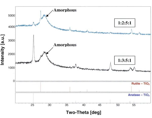
In Figure 3.2, the diffraction patterns of samples 1:2:9:1, 1:2:10:1, 1:2:12:1 and 1:2:14:1 were compared to the reference peaks of rutile and anatase TiO2. Figure 3.3 shows the
patterns of samples 1:3:9:1, 1:3:10:1, 1:3:12:1 and 1:3:14:1. While the samples exhibited no cracking or peeling and were highly crystalline, all the diffraction patterns show that there is significant amount of rutile TiO2 in each sample. Comparatively small traces of
anatase exist, but not enough for the films to have high catalytic activity. The goal is to produce a film with 100% anatase content. It is possible that because the sol-gel solution is diluted with large amounts of alcohol, the crystallization process is affected by the evaporation of these solvents. With the sol-gel process, as it was carried out in these experiments, the options are between low-crystallinity, cracked anatase TiO2 and
Two-Theta [deg]
500 250 4 250 .liI 25 30 35 40 45 50 55 Two-Theta [deg]
Figure 3.3: XRD patterns of sol-gel samples 1:3:9:1, 1:3:10:1, 1:3:12:1, 1:3:14:1.
3.2 Reactive D.C. magnetron sputtering
Sol-gel has proven to have its limitations in producing the requisite crystalline TiO2
films. Consequently, reactive D.C. magnetron sputtering was explored as an alternative method. Of the various physical deposition methods that are currently used, among them evaporation, ion beams techniques and chemical vapor deposition (CVD), reactive sputtering holds promise because of the high quality films that can be fabricated. In reactive D.C. magnetron sputtering, a magnetron utilizes an electric field to trap ions close to a metal target, inert gases in the chamber accelerate toward the surface of the target, and it is eroded. The metal particles then interact with the oxygen present in the chamber and the metal oxide molecules are deposited on the substrate. Reactive
sputtering generally forms amorphous films due to the impact of high energy molecules on film growth and the process involves slow deposition rates (on the order of 1 A/s). However, a post-anneal step crystallizes the titanium dioxide very well and films produced using this method are particularly robust.
3.2.1
Experiments
The titanium dioxide films produced for these experiments were done using an AJA International, Inc. (N. Scituate, MA) Orion 5 high-vacuum sputtering system. The vacuum chamber accommodated three magnetron guns - two RF and one DC - although only the DC gun was used. A substrate holder for substrates of 100mm in diameter was heated to temperatures ranging from room temperature (-250C) to 1000C. The target was
a titanium disk (2 in diameter, purity 99.9%) connected to a mechanism for water-cooling. Two gases-argon and oxygen-flowed through the chamber with the oxygen content ranging from 10% to 20%. The chamber pressure varied between 1.6mTorr and 3.6 mTorr and was controlled by a turbo pump operating at a pumping speed of 1000 Hz and the changing orifice of a throttle valve. The power supplied to the targets remained constant at 250W. The film deposition was always carried out in reactive mode, with oxygen always present in the deposition chamber. In this way, metal oxides of controlled stochiometry can be stably deposited. Table 3.1 below shows the test array for the experiments described.
The films were deposited on 3-inch single crystal silicon wafers and annealed for one hour in a 4500C anneal furnace in order to crystallize the films. The samples were then tested using glancing incidence X-ray diffraction (GIXRD) using the same procedure that was used for testing the sol-gel samples. Included in the table are the deposition rates measured by the quartz crystal monitor (QCM) located in the sputtering unit prior to depositing the films. All films were deposited such that the thickness was maintained at 50 nm. This proved thick enough to obtain a good diffraction pattern, with lots of signal received from the sample, yet was not so thick that long deposition times were required. In the next section, the results of the experiments are discussed and compared.
Table 3.2: Test array for film deposition experiments
Sample Deposition Pressure Teperature Deposition Rate pit I[mTo rr] in Argonk/S] i
1 1.6 5 RT 2.2 2 1.6 10 RT 2.1 3 1.6 15 RT 1.9 4 1.6 15 50 1.9 5 1.6 15 75 1.9 6 1.6 15 100 1.9 7 1.6 20 RT 1.6 8 2.6 15 RT 1.6 9 3.6 15 RT 1.5 10 3.6 15 50 1.3 11 3.6 15 75 1.4 12 3.6 15 100 1.4
3.2.3
Results and discussion
The figure below shows the diffraction patterns for samples 3, 8 and 9, under varying deposition pressures, 15% 02 content in the chamber and with room temperature
substrates. In literature, it is reported that high vacuum deposition is essential for anatase formation, but the exact deposition pressure recommended varies. Libl and colleagues suggest a chamber pressure equal or less than 0.7 Pa or 5.25 mTorr.30 All films under
5.25 mTorr in the experiments that were carried out in Lbl's study crystallized to pure
anatase after annealing. Therefore, in these experiments, deposition pressures of 1.6 mTorr, 2.6 mTorr, and 3.6 mTorr were chosen. The measured film deposition rate for pressures below 1.6 mTorr was too low to consider for film fabrication.
35 40 45
Two-Theta [deg]
Figure 3.4: XRD patterns of sputtered samples of varying deposition pressure.
Figure 3.4 clearly illustrates that a deposition pressure of 3.6 mTorr yields pure anatase TiO2. At pressures lower than 3.6 mTorr, the rutile content increases and anatase
decreases. The increase in rutile content could possibly be explained by the following reasoning: At very low pressures, the Ti ions interact with the oxygen in the chamber and bombard the substrate with high energy. It is known that the energy of the metal oxide particles being deposited has an effect on how the crystals form in the film. The higher the energy of the particles, the higher the rutile content will be. Another point to note is that, in all the sputtered films, there is no amorphous TiO2 and almost the whole film is
crystallized. This differs from the sol-gel experiments in which there was amorphous content. In fact, the film deposited at 3.6 mTorr exhibits very high crystallinity because the peaks in the diffraction pattern are relatively high and narrow.
The deposition system that was used allowed for sample heating to temperatures up to 8000C. We investigated the effect of sample temperature on the crystallization of the TiO2 films. Since as-deposited titanium dioxide films are generally amorphous and
annealing causes crystallization, it was hypothesized that a heated sample could promote the growth of anatase as deposition occurred and a post-anneal step would not be
necessary. After the samples were deposited, our hypothesis proved incorrect; sample heating also resulted in amorphous films as-deposited. We annealed the samples and three diffraction patterns from the resulting films are shown in the following figure.
Figure 3.5 shows the effect of sample temperature on crystallization. As it turns out, the higher the sample temperature, the more rutile TiO2 forms after annealing. The film
sputtered at room temperature showed the best results, with all of the film exhibiting pure anatase crystallization. It seems that the nucleation of rutile TiO2 is favored when the
impinging titanium dioxide particles, formed reactively in the region between the Ti target and sample, have high energies. The formation of rutile is also promoted by the presence of Ti atoms in the vapor phase, which is possible at higher sample temperatures.
Two-Theta [deg]
Figure 3.5: XRD patterns of sputtered samples of varying sample temperature.
Figure 3.6 shows the diffraction patterns of films deposited under 10%, 15% and 20% oxygen content, at a deposition pressure of 1.6 mTorr and on samples at room
temperature. It has been shown that films sputtered at 1.6 mTorr form rutile when the oxygen content is 10%, but the patterns shown below indicated that increasing the ratio of oxygen to inert gas (Ar in this case) favors the formation of anatase after films are annealed. As mentioned earlier, nucleation of rutile is promoted by the presence of Ti in vapor phase in the vicinity of the substrate onto while the titanium dioxide is being deposited. Increasing the ratio thus favors anatase formation because the Ti vapor is minimized. The results below illustrate, however, that much more oxygen is required to produce pure anatase and to obtain films of high crystallinity.
500C
1000C
L~~ii
0
15% 02 . 500I
I
J
C )20% 02 0 Rutile - TiO2 Anatase - Ti02 25 30 35 40 45 50 55 Two-Theta [deg]Figure 3.6: XRD pattern of sputtered samples of varying oxygen content.
3.3 Conclusions
The experiments discussed in this chapter compare two different methods of titanium dioxide film deposition. Sol-gel and reactive sputtering, one a wet-chemical technique and the other a physical deposition method, were found to yield very different products. Although sol-gel is an inexpensive and quick means of producing metal oxide films, it was deemed difficult to obtain films that fit both criteria that were outlined in the
beginning of the chapter - highly crystalline anatase TiO2 and smooth films. Although a
wet-chemistry protocol is easier to follow, there were several complications encountered because the viscosity of the sol-gel solution, solvent evaporation and crystallization were difficult to control.
The preparation of titanium dioxide thin films using a sol-gel protocol was abandoned for a more expensive and time-consuming process. Sputtering, however, has been found to yield thin films that were mechanically robust and highly crystalline anatase in
composition. After performing the experiments, the protocol that was settled on was that which formed the film of sample 9 in Table 3.1. The films were deposited using reactive D.C. magnetron sputtering, at a power of 250W, under a deposition pressure of 3.6 mTorr, in a chamber that contained 15% 02 and 85% Ar gas and at room temperature. The deposition rate remained roughly at 1.5
A/s.
In Chapter 4, the next steps - where the anatase titanium dioxide thin film developed is incorporated into a microfluidic device for blood oxygenation - are discussed.Chapter 4
Microfluidic Device Design and
Experimentation
In recent years, researchers have been investigating the possibility of using photocatalytic oxygen generation to address deficiencies in pulmonary respiration.31' 32' 33,34 In particular,
efforts have been made to reproduce a photoelectrochemical cell in a fluidic device for blood oxygenation. In Chapter 2, the mechanism by which oxygen is produced in such a cell, as well as how blood oxygenation occurs in vivo, were reviewed. In Chapter 3, the photocatalyst film fabrication was explored. The present chapter describes the design of the novel microfluidic device that is proposed and the experimental work that validates its function.
The novel approach outlined here can be used to oxygenate whole blood and treat patients with chronic and end-stage lung disease in real time. The goal is to create a self-contained, mobile oxygen supply suitable for implantation in patients that will reduce the complications they suffer from current treatments. Specifically, we focused on the
development of a highly efficient photocatalytic cell (PC) with the ability to continuously oxygenate venous blood under steady-state conditions.
At the time the work discussed in this thesis was conducted, the only other researchers investigating photocatalytic blood oxygenation were A. Subrahmanyam and his
colleagues at the Department of Physics in the Indian Institute of Technology in Chennai, India. Our approach to the artificial respiration differs in several ways from theirs. First, we are the first to integrate the photocatalytic semiconductor thin film into microfluidics. The use of soft polymers, like polydimethylsiloxane (PDMS), in a device is beneficial because of its biocompatibility and ease with which it can be molded into various channel
geometries. Second, the ultimate design of the microfluidic device for artificial
respiration will be implanted in vivo and blood will be flowing continuously through it by the pumping power supplied by the heart. Therefore, the transport of oxygen to the blood is done in real-time, as it is in normal pulmonary function. The Subrahmanyam design has the blood remaining stationary in a reservoir while photocatalysis takes place.
Our device design is outlined as follows.
4.1 Photocatalytic cell (PC) design and
fabrication
The photocatalytic cell that was designed is illustrated in Figure 4.1. It is composed of three main components:
(1) a highly crystalline anatase TiO2 thin film deposited onto a conducting indium tin
oxide (ITO) thin film to form a semiconducting junction of TiO2/ITO,
(2) a platinum (Pt) electrode that is exposed to blood flowing through the channel and by means of which a bias potential can be maintained, and
(3) microfluidic channels molded out of polydimethylsiloxane (PDMS)
The blood flowing in the microfluidic channel is in direct contact with the TiO2 film, and
water in blood plasma (more than 90% of which is water by volume) is oxidized to produce dissolved oxygen gas. During the fabrication process, TiO2 is sputtered onto a
conductive ITO film that has already been deposited on the quartz substrate. Above the fluidic channel is a platinum electrode that is deposited onto PDMS. Between the ITO and Pt electrode, a bias potential is maintained to enhance the migration of electron vacancies, or holes, to the photocatalyst/fluid interface so that oxidation reactions can take place there. The bias also conducts away the electrons generated in the bulk of the
photocatalyst when the holes are created. The set-up of the cell in Figure 4.1 is analogous to the photoelectrochemical cell in Figure 2.5 in Chapter 2.
bias voltage
m-
-Pt electrode film
quarti wafer
tU
tTtttt
TiO2thin film
Figure 4.1: A) Schematic and B) photo of assembled device.
A
channel i
in PDMS
4.1.1
ITO/TiO
2thin film deposition
The metal oxide thin films were deposited onto three-inch diameter quartz wafers (Mark Optics Inc., Santa Ana, CA) which served as the substrates for the microfluidic devices. Quartz glass (thickness of 700 iim + 100 [tm) was chosen because it has a transmittance of approximately 96% in the UV range. Indium tin oxide was chosen for the conductive layer because it has a 90% transmittance of UV light and a conductivity of about 104 S/cm. The operation of the device relies on the irradiation of the photocatalyst and, as shown in Figure 4. 1A, the UV light must pass through the glass and ITO film before it reaches the TiO2 film. Therefore, a high transmittance for both materials is necessary.
As can also be seen from Figure 4. 1A, the bias voltage that is applied across the channel relies on closing the circuit between the Pt electrode and the ITO layer. ITO was
patterned onto the substrate according the schematic in Figure 4.2. TiO2 was patterned
only in the channel region where it is exposed to the blood. The channel for the design of this proof-of-concept microfluidic device is simply rectangular, 4.5 mm in width and 25 mm in length, as the goal was to demonstrate device's capability of blood oxygenation. The minus (-) sign in the figure below indicates that the anode of the electrical circuit is the ITO film underneath the photocatalyst. Once the microfluidic device is assembled, the Pt electrode (which serves as the cathode) will be connected to the U-shaped ITO film that is denoted by the plus (+) sign in the figure below.
i
*TiO, ouer ITO
+
-
-mmmmml
Figure 4.2: Schematic of patterned ITO and TiO2 thin films. The (-) and (+) signs refer to
![Figure 2.4: Schematic illustration of decomposition of acetic acid. [Reproduced from Kaneko and Okura, 2002]](https://thumb-eu.123doks.com/thumbv2/123doknet/14732586.573362/27.918.269.668.577.952/figure-schematic-illustration-decomposition-acetic-reproduced-kaneko-okura.webp)