HAL Id: hal-00173132
https://hal.archives-ouvertes.fr/hal-00173132
Submitted on 19 Sep 2007HAL is a multi-disciplinary open access archive for the deposit and dissemination of sci-entific research documents, whether they are pub-lished or not. The documents may come from teaching and research institutions in France or abroad, or from public or private research centers.
L’archive ouverte pluridisciplinaire HAL, est destinée au dépôt et à la diffusion de documents scientifiques de niveau recherche, publiés ou non, émanant des établissements d’enseignement et de recherche français ou étrangers, des laboratoires publics ou privés.
New bottom-up algorithm for assembly plan generation :
opportunities for micro-factory design.
Christophe Perrard, Philippe Lutz, Paulo Salgueiro
To cite this version:
Christophe Perrard, Philippe Lutz, Paulo Salgueiro. New bottom-up algorithm for assembly plan generation : opportunities for micro-factory design.. IEEE International Symposium on Assembly and Manufacturing, ISAM’07., Jul 2007, Ann Arbor, Michigan, United States. pp.sur CD ROM - 276-281. �hal-00173132�
New bottom-up algorithm for assembly plan generation:
opportunities for micro-factory design
Christophe PERRARD(1), Philippe LUTZ(1), Paulo SALGUEIRO(2)
This paper discusses about a new approach dedicated to assembly plan generation, called "bottom-up algorithm". It is compared to the traditional "top-down approach", usually used to perform such a stage when designing assembly systems for "macro-products". The aim of this paper is to adapt this stage to a new "micro-assembly systems" design method an to discuss the advantages of the proposed algorithm. The case of watch assembly plans generation is described through the both approches and results are compared.
Key words: assembly plan generation, assembly, micro-assembly, assembly system
design
(1) Laboratoire d’Automatique de Besançon, Institut de Productique, 25 rue Alain Savary, 25000 Besançon, (2) CEA de Valduc, Bat 120 - 21120 Is Sur Tille
1. Introduction: context of assembly plans generation for micro-products [Lutz 05]
Today, lot of very small dimensions products are used in many different activities, like lens for endoscopes, luxury products (watches), hybrid systems (MEMS and micromechanics),…
However, production assembly systems dedicated to these micro-products aren't efficient today. This is due to
- the "great" size of the used equipments (before micro-size of products),
- the difficulties to access to micro-objects,
- the particular physical phenomena that are prevailing in the micro-world,...
One solution is to adapt the size of such assembly systems to the size of micro-products to obtain. The benefits of this point of view are:
- a reducing of the energy consumption, - a saving of material,
- a great portability of the "factory" to any location, - the greater facility of its insertion in clean room areas,
- the hope of reducing equipments costs and delivery delays,
-…,
However, "micro-factories" can't be the result of a trivial size reducing of "macro-factories", due to the particular physical phenomena and to the non-assessibility to the human operator. Thus, micro-factories will have to be highly automatized, strongly modularized, and easy to reconfigure.
Today, there are some examples of reduced size micro-assembly cells, but not a convincing solution, that results from an organized micro-assembly system design method. This is due to the non existence of such a method for micro-products assembly.
The design of flexible, modular and automated micro-factories has to take under consideration the stage of the research of pertinent assembly plans. Today, such a tool exists for "macro-products", but seems not good adapted to solve "micro-assembly plans" generation.
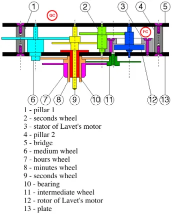
Our purpose will be illustrated through the solving of a watch mechanism (figure 1)
1 - pillar 1 2 - seconds wheel 3 - stator of Lavet's motor 4 - pillar 2 5 - bridge 6 - medium wheel 7 - hours wheel 8 - minutes wheel 9 - seconds wheel 10 - bearing 11 - intermediate wheel 12 - rotor of Lavet's motor 13 - plate
fig. 1: example of micro-product: a watch mechanism 2. Problem modellings
2.1. Product modelling
The end product P is represented by its liaison graph [C, Γ], where C is the set of the nodes representing the elementary parts and where Γ is the set of the arcs representing geometric liaisons between the elementary parts (figure 2a). This is the liaison graph used by [Henrioud 89]. They are called geometrical characters.
Some others characters have to be performed in order to satisfy the product's specifications sheet. They are fixtures (screws, soldering,…), auxiliary characters (cleaning, marking…) or quality characters (end control,…). They are called non-geometrical characters (figure 2b).
A non-geometrical character is described by a couple [C,O], where
- C is the sub set of parts concerned by the non-geometrical character,
- O is the sub set of non-geometrical characters concerned by the character (precedence relations). Note that usually, O=∅ for a fixture.
L e t t h e [ C1,Γ1,O1] t r i p l e t ( w h e r e C⊃C1,Γ⊃Γ1,O⊃O1) describe any sub-assembly of the product.
For the watch mechanism, liaisons between wheels and gears are not taken under consideration, because an isolated gear and wheel isn't a pertinent sub-assembly.
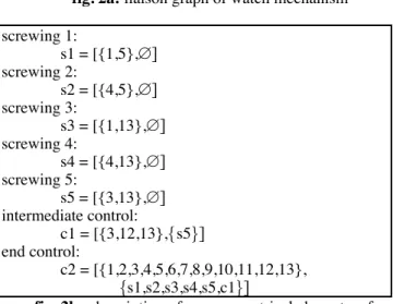
fig. 2a: liaison graph of watch mechanism
screwing 1: s1 = [{1,5},∅] screwing 2: s2 = [{4,5},∅] screwing 3: s3 = [{1,13},∅] screwing 4: s4 = [{4,13},∅] screwing 5: s5 = [{3,13},∅] intermediate control: c1 = [{3,12,13},{s5}] end control: c2 = [{1,2,3,4,5,6,7,8,9,10,11,12,13}, {s1,s2,s3,s4,s5,c1}]
fig. 2b: description of non-geometrical characters for
watch mechanism
2.2. Assembly plans modelling
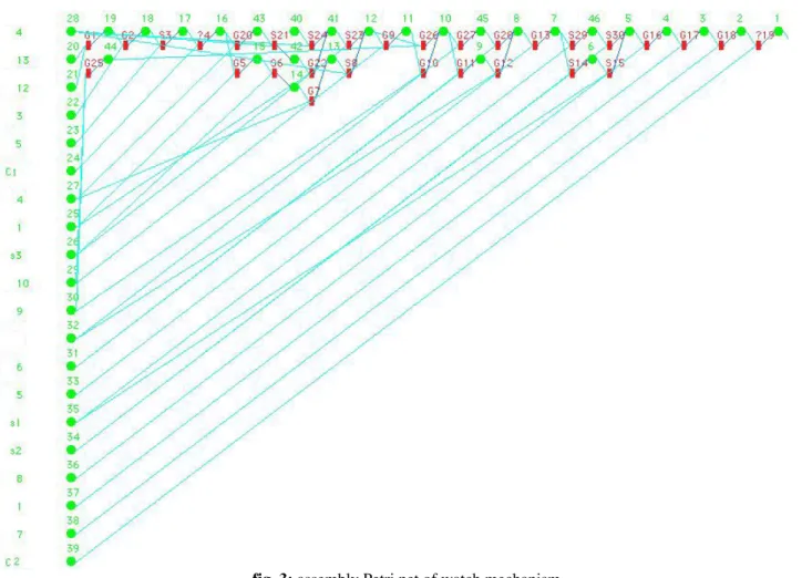
The result, in other words the set of assembly plans of the product, is an assembly Petri net (figure 3) [Perrard 00], where:
- places represent sub-assemblies, elementary parts and the end-product,
- transitions represent the potential operations to perform,
- the arcs from place to a transition represent the sub-assemblies needed to perform this operation (and condition),
- the arcs from transition to a place represent different decomposition-ways of this sub-assembly (or condition).
An assembly plan is a particular path inside the assembly Petri net.
The assembly Petri net of watch mechanism, figure 3, contains 16 assembly plans.
3. First approach: top-down algorithm 3.1. Description
The LAB (Laboratoire d'Automatique de Besançon) has worked since many years on assembly plans generation.
The approach used by the classical top-down algorithms lies on a decomposition method of the product modelling [Henrioud 89] [Homem 89] [Delchambre 92].
Starting from the whole product P, the algorithm searches first all the possibilities to decompose the product modelling [C, Γ,Ο] into two triplets of sub-modelling ([C1,Γ1,Ο1], [C2,Γ2,O2]) such as:
[C1,Γ1] and [C2,Γ2] are connected sub-graphs, [C1,Γ1,Ο1]≠[C2,Γ2,Ο2]≠[∅,∅,∅],
C1∪C2=C, Γ1∪Γ2∪Γ12=Γ, O1∪O2=O,
C1∩C2=Γ1∩Γ2=O1∩O2=∅.
Γ12 is called cocycle and represents the created liaisons between the two joined sub-assemblies.
Each decomposition in a couple of sub-modelling ([C1,Γ1,Ο1], [C2,Γ2,Ο2]) represents a potential assembly
operation, noted (P1, P2), joining two virtual
sub-assemblies (P1), (P2).
Usually, a decomposition represents:
- a geometrical operation, when the cocycle Γ12≠∅ - a non geometrical operation, when:
- Γ12=∅
- [C2,Γ2,Ο2]≠[∅,∅,{ο}], with o=[Co,Oo], C1⊃Co and O1⊃Oo
If the operation is feasible, the algorithm proceeds recursively for each resulting virtual sub-assemblies until the resulting sub-assemblies are reduced to a single component of P, like [{c},∅,∅], or a single non-geometrical character of P, like [∅,∅,{o}].
An assembly operation isn't feasible if there is an assembly constraint between P1 and P2.
3.2. Assembly constraints
An operation is feasible if there is no constraint to forbid this operation. The constraint may be a strategical
constraint that is a priori defined to reject the worst
assembly plans, or it may be an operative constraint, determined by the designer during the assembly planning
process.
Strategical constraints are given by the user before solving the assembly plans research. For the watch mechanism, we imposed:
- to assemble first Lavet's motor and control it (to minimize product's added value if assembly operation
fails),
- to finish and close the internal mechanism before assemble the external wheels (to minimize product's reorientations),
- to fix as soon as possible every screw (to minimize sub-assemblies unstability).
fig. 3: assembly Petri net of watch mechanism
There are 3 kinds of operative constraints:
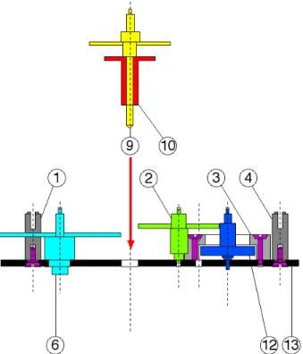
- the geometric constraints: an assembly operation is
feasible if it exists a trajectory allowing to join the two parts (figure 4). Let CG(P1,P2) be such a constraint.
Property 1:
If it is impossible to join two sub-assemblies because of geometrical considerations, then it's impossible to perform any other operation where sub-assemblies P'1 and P'2 contains P1 and P2:
CG(P1,P2) ⇒ CG(P1∪Q1,P2∪Q2)
Property 2:
CG(P1,P2) is a minimum geometrical constraint, if it doesn't exists another geometrical constraint CG(P'1,P'2) where P1⊃P'1 and P2⊃P'2
- the stability constraints: the assembly operation is
feasible if the two parts are stable during the joining process,
- the equipment constraints: it requires the existence
of some equipment liable to perform the candidate
assembly operation.
The “cut-set” algorithms have the advantage of completeness [Sanderson 91]. They are powerful when the geometric and the strategic constraints are strong. In that case, the number of assembly plans is moderate and the computation time is reasonable.
The operative constraints determination may be performed with the help of specific CAD procedures [Delchambre 96]. However, such tools are only prototypes in laboratories, until today.
fig. 4: Example of geometric constraint for the watch
mechanism assembly
3.3. Limitation of such an algorithm
3.3.1. Any point of view
The main principle of product modelling decomposition [C,Γ,Ο] ⇐ [C,Γ,Ο] ∪ [C,Γ,Ο] ∪Γ12 is quite complex. It requires lot of computer ressources and long operation times. Most of the breakdowns don't produce a pertinent assembly operation. This is more critical at the beginning of the algorithm, when the whole product is concerned.
Because the generation process starts from the whole product modelling to the elementary parts, first responses of the user produce non minimal geometrical constraints. Then, user answers several times to similar questions, where the same minimal geometrical constraint is included.
3.3.2. Micro-assembly plans generation point of view
Such top-down generation is efficient enough for assembly plan generation only if product modelling if considered. In micro product assembly case, the physical effects that appears during the micro-assembly operation performing has to be considered [Lambert 03] and [Lambert 06]. These effects are adhesion forces (due to capillarity, Van Der Waals forces, electrostatic forces…) or rejection forces. They usually are predominant before the weight of micro-components. Nevertheless, these particular effects depend on joined sub-assemblies and on the used tools both. Then, used tools depends on the already performed operation to obtain present joined sub-assemblies (such the gripper, the fitting device,…).
Then, in such a case, the top-down approach has to be replaced by a bottom-up approach, in order to know the genesis of the sub-assemblies and to include the used
tools. During assembly plans generation, considered objects has to become aggegates, that are the union of a product objects and assembly system tools (grippers, fitting devices,…)
4. New appoach: bottom-up algorithm 4.1. Objects and constituents
An object is the result of a set of assembly operations applied to a set of elementary parts and non-geometric characters. However, the result of the performing of these operations isn't necessary a usefull object (figure 5). Because the set of performed operations can be empty, any elementary part and any non-geometric character is an object too.
A constituent is any object that can exists into the assembly system and that can leads to the end product. It can be an elementary part, any non-geometric character, the end product, or a sub-assembly. Thus, a constituent is a usefull object.
fig. 5a: Inclusion of sets for different objects
fig. 5b: Example of feasible operation producing a
non usefull object for watch mechanism assembly
4.2. Object's level
The level of an object is equal to the number of the included elementary parts added to the number of the included non-geometric characters it enhances. I.e, if an end product contains n components and m non-geometric characters, the level ot this end product is n+m ; the level of an elementary part is 1 ; the level of any non-geometric
character is 1.
4.3. Algorithm
At the beginning of the algorithm, any constituent of level 1 is known, because on the modelling of the end product.
The computation process starts from level 2 to level n+m (end product level).
Any object C of level i>1 is the assembly result of 2 known constituents C1 and C2 of level j and k respectively as well as j + k = i and where C1∪C2=C, C1∩C2=∅ (see operation constraints generation, §3.1, they are the same) . In order to compute each operation in one single time, we impose the supplementary constraint j≥k.
4.4. New kind of object constraints: dead-end objects
Sometime, using the bottom-up algorithm, feasible operations may produce non usable objects (figure 6). If such an operation is accepted by the user, the resulting object will not allow to obtain the end-product. Then, we call such a result "dead-end object". There is no relation between a "dead-end object" and a dead-lock phenomenon, as described by [Bonneville 91].
fig. 6: Example of dead-end object of watch
mechanism
Any other object, obtained by assembly operations from a "dead-end object" is another "dead-end object" too. Any "dead-end object" doesn't allow to obtain the end-product.
An object O1 is a "dead-end object" if a constituent C2 exists, wich level is 1 (then, C2 is an elementary part or a character), such as a geometric constraint between O1 and C2 exists: CG(C1,C2). We call C2 the complement of O1 for the geometric constraint CGi.
Because the end product exists, the level of any dead-end object is equal or more than 2 and is minus than n+m.
Thus, any assembly operation between C1' and C2', where C1'⊃O1 and where C2'⊃C2, is impossible, due to a geometric constraint too (propertie 1 of geometric constraints).
Then, the bottom-up algorithm allows to find first the minimum geometric constraint, by indicating the dead-end objects O1 and their complements C2, in order to produce the corresponding elementary geometric constraint.
In a second hand, the algorithm is very simple because objects to join are still verified and validated by the algorithm when performing lower levels.
4.5. Cleaning of the assembly Petri net
Dead-end objects don't allow to obtain the end-product. At the end of bottom-up algorithm, inside the assembly Petri net, some places exist, representing some "terminal" dead-end objects, where no arc starts to another operation (well place). Then, at the end of the bottom-up algorithm, a cleaning stage allows to suppress these non pertinent objets. When a "terminal" dead-end object is detected, it is removed as well as the operations that produce this objet. The cleaning algorithm proceeds recursively, until any other"terminal" dead end object is detected.
5. Conclusions
5.1. Comparizon between top-down and bottom-up algorithms
Complexity of buttom-up algorithm is lower than top down one, because:
- the manipulated objects are more simple.
- the second proposed generation process try to match only usefull and still known objects (no graph connexity computation).
Due to the fact that minimal geometric constraints are found first, user is less requseted and number of questions strongly decreases.
For the watch example, top-down algorithm asked 37 questions to the user and bottom-up algorithm asked only 25 questions to the user. In the second case, these questions are very easier to answer.
These good results are only an indicator. We were not able to compare precisely performances (like computation times or CPU request,…) because the top-down algorithm is implemented in AI language Prolog II (from Prologia) on Macintosh G4 computer, when the bottom-up algorithm is written in C++ (from Borland) and runs on PC equiped with Pentium III. However, for the watch example, the two algorithms ran less than the minute to solve the problem.
When including tool considerations, questions and algorithm comlexity will strongly increase. It will be the challenge to dominate it.
5.2.. Some improvements: introducing assembly system tools
As explained in §3.3.2., the first motivation to write this new bottom-up algorithm was the tools introduction into the micro-asembly plans generation.
Today, this stage isn't implemented yet, but it's our main goal in the early future. First works, about micro-products and specifics effects modelling are under devlopment [Benbelkacem 05].
However, the obtained results are pertinent to improve efficiency of "usual" assembly system design methods.
Acknowledgments
Authors thanks CEA of Valduc France, and staff, for their comments and help during the development of this
work.
REFERENCES
[Benbelkacem 05] S. Benbelkacem, C. Perrard, P. Lutz
Nouvelle approche de modÈlisation des micro-produits en vue de la gÈnÈration des gammes d'assemblage.
Actes du 6Ëme CongrËs International de GÈnie Industriel, GI'2005, CD ROM, 10 pages, 7-10 juin 2005, BesanÁon, France.
[Bonneville 91] F.Bonneville, P.Baptiste, H.Manier
Representation of a set of process plans for the real time control of a flexible assembly system
Proceeding of Int; 91 Warsaw Conf., Poland, 1991.
[Delchambre 92] A. Delchambre
Computer-aided assembly planning
Chapman & Hall, London, UK, 1992 [Delchambre 96] Delchambre,A.
CAD Method for Industrial Assembly
edited by A. Delchambre, John Wiley & Sons, 1996
[Henrioud 89] Henrioud, J.M.
Contribution à la conceptualisation de
l'assemblage automatisé: nouvelle approche en vue de la détermination des processus
d'assemblage
Thèse d'état, Université de Franche-Comté, 1989 [Homem 89] Homem De Mello,L.S.
Task sequence planning for Robotic Assembly
Ph. D Thesis, Carnegie Mellon University, May 1989.
[Lambert 03] P.Lambert, A.Delchambre
Forces Acting on Microparts: towards a numerical approach for gripper design and manipulation strategies in micro-assembly.
Proc. of the 1st Int. Precision Assembly Seminar (IPAS), Bad Hofgastein, Austria, pp. 79-84, 2003, edited by Svetan Ratchev and AlainDelchambre.
[Lambert 06] P.Lambert, S.Régnier.
Surface and contact forces models within the framework of microassembly.
Journal of Micromechatronics 3(2): 123-157, 2006
[Lutz 05] P. Lutz, D. Gendreau, Y. Haddab, C. Perrard
Microfactories: a new kind of production systems for micromechatronic products.
Proc. of the 1st European Advanced Technology Workshop on Mechatronics, iMAPS'2005, CD ROM, 24 pages, 17-18-19 janvier 2005, Poitiers, France.
[Perrard 00] Perrard C. Henrioud J.M., Vallet G.
Assembly systems design: a practical approch for industrial cases
16th International Conference on CAD/CAM, Robotics and Factories of the Future, Cars & Fof 2000, June 26-28, Port of Spain, Trinidad W.I., 2000
[Sanderson 91] A.C. Sanderson, A.C.; Homem de Mello, L.S.
A correct and complete algorithm for the generation of mechanical assembly sequences
IEEE Transaction on Robotics and Automation, Vol. 7, n°2, 1991, pp.228-240.