Publisher’s version / Version de l'éditeur:
Fire Technology, 1, 2, pp. 93-102, 1965-10-01
READ THESE TERMS AND CONDITIONS CAREFULLY BEFORE USING THIS WEBSITE. https://nrc-publications.canada.ca/eng/copyright
Vous avez des questions? Nous pouvons vous aider. Pour communiquer directement avec un auteur, consultez la première page de la revue dans laquelle son article a été publié afin de trouver ses coordonnées. Si vous n’arrivez pas à les repérer, communiquez avec nous à [email protected].
Questions? Contact the NRC Publications Archive team at
[email protected]. If you wish to email the authors directly, please see the first page of the publication for their contact information.
NRC Publications Archive
Archives des publications du CNRC
This publication could be one of several versions: author’s original, accepted manuscript or the publisher’s version. / La version de cette publication peut être l’une des suivantes : la version prépublication de l’auteur, la version acceptée du manuscrit ou la version de l’éditeur.
Access and use of this website and the material on it are subject to the Terms and Conditions set forth at
Ten rules of fire endurance rating
Harmathy, T. Z.
https://publications-cnrc.canada.ca/fra/droits
L’accès à ce site Web et l’utilisation de son contenu sont assujettis aux conditions présentées dans le site
LISEZ CES CONDITIONS ATTENTIVEMENT AVANT D’UTILISER CE SITE WEB.
NRC Publications Record / Notice d'Archives des publications de CNRC:
https://nrc-publications.canada.ca/eng/view/object/?id=5cdeb7ca-ea67-4315-af4b-4b7368b6453b https://publications-cnrc.canada.ca/fra/voir/objet/?id=5cdeb7ca-ea67-4315-af4b-4b7368b6453bt , T /
Neronel
Resenncx CouNctl
CANADA
Conseru Nltronnl DE RecxrncHrs
TEN RULES
OF FIRE ENDURANCE
RATING
BY T. Z. HARMATHY
A N A L Y Z E D
R E P R I N T E D F R O M FIRE TECHNOLOGY.
voL. t. No. 2, MAY 1965, P. 93 - lO2
TECHNICAL PAPER NO, 206 OF TI{E
DIVISION OF BUILDING RESEARCH
OTTAWA ocToBER 1965 Ser TH]-N2Lt2 no. 206 e . 2 BI.DG PRICE 26 CENTS
3 7 868A
I t
DIX REGLES POUR DETERMINER LES
/
TAUX DE RESISTANCE AU FEU
SOMMAIRE
Les essais drendurance au feu ne suffisent pas pour obtenir toutes les donn6es dont on a besoin pour 6va-luer judicieusement les taux de r6sistance au feu des 6l6ments de construction. Il existe beaucoup trop de modes dtagencement des mat6riaux pour pouvoir les c l a s s e r t o u s a u m o y e n d e s e s s a i s s u s m € n t i o n n 6 s . H e u -reusernent, la th6orie des taux de r6sistance au feu e st suffis arnment d6velopp6e pour f aciliter 1'6valuation de ces taux. Lrauteur donne dix rbgles susceptibles d e f a c i l i t e r l t 6 v a l u a t i o n d e s c a r a c t 6 r i s t i q u e s d e r 6 s i s -tance au feu des 6l6ments de construction lorsquron ne dispose pas de donn6es fond6es sur des essais d r i n c e n d i e .
N.EPnINTED FBOU
FIRE TECHNOIPGY
VoL I No.z , AY 1965
Ten Rules tf
Fire Endurance Rating
T. Z. HARMATIIY
Diuisinn of Building Rew.rch
National Rmrch. CounciJ (Canad.a)
Fire endurance tesLs alone cannot supply all the data needed for intelligent appraisal of fire resistant ratings of building ele-ments. There are simply too many different types of assemblies and combinations of materials to classify them all through actual tests. Fortunately, the theory of fire endurance rating is suf-ficiently advanced to offer guidance in estimating fire endurance ratings- The author sets forth ten rules that may prove useful for quick assessnent of the fire endurance of building elements when fire test data on the elements are not available.
fT IS becoming increasingly evident that all the information necessary I for classifying building elements from the point of view of their per-formance in fre cannot be derived from standard fire endurance tests alone. It is hardly conceivable that all various constructions can ever be subjected to fire tests. Even in those cases where test results are available for more or les similar constructions, the classification may not be immedi-ately apparent. It must be clearly understood that certain variations in the dimensions, loading conditions, materials, or workmanship may mark-edly affect the performance of the individual constructions, and the extent ofsuch a possible efrect cannot be evaluated from the fire test report.
The value of the pieces of information obtained from standard fire tests is very limited without a theory that is capable of cementing the piees into a consistent unit. Fortunately, the theory of fire endurance rating has already advanced far enough not only to offer some guidance in estimating the effect of certain variables on fire endurance but, very often, even to provide rigorous methods of designing building elements for some prescribed performance.
Although the design for fire endwance, whenever possible, is a fairly complex procedure, involving extensive laboratory investigations and some-times very laborious heat-flow and stress-deflection analyses, it will al-ways prove of extreme value when developing new building products for
Coeyiehl 1965 NAIIONAI FIRE PROTECnON ASSOCIATION 60 BATTERYMARCH ST., BOSTON, IAA5S. O2IIO
93
P.inr.d in U.5.4.
94 Fire Technology maximum economy. In the case of products already on the market, the problem of economy no longer remains, and the question of whether the product will yield a fire endurance higher than some given value may not deserve an extensive theoretical study.
In this report a number of rules will be discussed which may prove useful in the quick appraisal of the fire endurance of building elements. Some of the rules are concerned with the geometry of the construction, some with the materials. All of them are based on experimentally and theoretically well-founded facts. It is hoped that these rules will provide some guidance to those charged with administering building bylaws, and to those who are engaged in either the design or production of building components. Examples are given to illustrate the wide applicability of these rules.
T H E T E N R U L E S
Rule 1: Thc "thermnL"* fr,re endurance of a construction consisting of a number of parallel layers is greater tlwn tlrc sum of the "tlrcrmaL" fire en-durances clwractcristic of thc indiuidual layers whcn exposed separatcly to fire.
This rule is probably the most important aid in assessment of the per-formance of building elements in fire, and suggests that the result of fire tests conducted on individual components of building elements, e.g., on gypsum board, plywood, brick veneer, plaster on expanded metal lath, etc., with the purpose of determining their "thermal" performance, may also be of considerable value. It is very convenient to use small-scale specimens for these "nonstandard" informative tests.
Because of the difficulties involved in the analytical treatment of the problem of heat flow through composite slabs, it is not possible, at present, to provide proof of this rule. Nevertheless, its validity has been confirmed by the result of several numerical analyses and small-scale fire tests con-ducted on both combustible and noncombustible constructions.
There is a special case in which the validity of Rule 1 is immediately obvious, i.e., the case of a "quasi-composite" construction consisting of layers made from the same material. It is known (and can be proved by the method described in Reference 1)' that by doubling the thickness of a slab, the fire endurance becomes more than twice the original value. Similarly, for a slab of rl thickness (in other words, consisting of n identical layers of thickness l),
t ^ 1 ) n t 1
where f is the time of fire endurance and the subscripts denote the thickness of the slabs. This inequality is an expression of Rule 1 for such a "quasi-composite" construction.
*The "therrnal" fire endurance is the time at which the average temperature on one side of a construction exceeds its initial value bv 250"F when the othei side is ex-posed to a "standard" fire specified by ASTM Metliod E119.
Fire Endurance Rating Rules 95 It may be noted that there are a few cases in which Rule 1 may not be applicable. If, for example, the unexposed surface is covered with a thin, shiny, -etal sheet, the radiant heat transfer to the surroundings may be-oome very low due to a decrease in the surface emissivity. Since the in-sulating value ofthe sheet is negligible, the fire endurance ofthe construc-tion might be lower than it would be without the presence of the sheet. It is atso conceivable that the inclusion of a layer which, in itself, exhibits no appreciable fire endurance, but is liable to undergo some chemical re-action accompanied by large exothermic effects at elevated temperatures, will upset the validity of the rule. These are, however, examples not likely to be met in practice.
RuLe 2: TIrc fi,re end,urance of a constrtrction does rwt d,ecrease with tlw add,ition of furtlwr Layers.
This rule is apparently a consequence of the previous rule. Its validity also follows from the fact that, by the addition of further layers, both the rcsistanoe to heat flow and the heat capacity of the construction increase, which, in turm, reduce the rate of temperature rise at the unexposed surface.
Although this rule seerns quite obvious, a close examination will reveal that it may be subject to certain limitations. Thus, in the light of what hbs already been noted, it is clear that the addition of a thin metallic layer to the unexposed surface does reduce the fire endurance of the existing con-struction. AIso, since in this rule "fire endurance" is considered in its most general meaning, certain restrictions must be imposed on some properties of the materials to be added, and on the load conditions.
An apparent restriction is that a new layer, if applied to the exposed surfae, must not produce additional thermal stresses in the construction, i.e., its thermal expansion characteristics mtrst be similar to those of the adjaoent layer. Each new layer must be capable also of contributing to the load-bearing capacity of the construction at least as much as is required to carry the increased dead load. If this requirement is not fulfiIled, the allowable live load must be reduced by an amount equal to the weight of tbe new layer. Because of these limitations, this rule should not be applied without due criticism.
Ruh 3: Thc fire end.urance of constru,ctions containing continuous air g@ps or witics is greatcr than the fire endurance of sirnilar constructions of tJu nrne untght, but containing rn air gaps or caaities.
The validity of this rule rests on the fact that by providing for voids in a conshuction, additional resistances are produced in the path of heat flow. Numerical heat flow analyses indicated that a 10 to 15 per cent in-cnease in fire endurance can be achieved by creating an air gap at the mid-plane of a brick wall.2 Since the gross volume of constructions is also in-creased by the presenoe ofvoids, the air gaps and cavities have a beneficial efrect on the stability as well. However, constructions containing
com-96 Fire Technology bustible materials within an air gap may be regarded as exoeptions to this rule because of the possible development of burning in the gap.
Rule 4: Thc farthcr an air gap or mtily is lmtd fum tlrc erpod surface, thc mare benefi.cinl, is its efet on tJrc firc edutww.
In the heat transfer through an air gap or cavity, radiation is the pre-dominant mechanism. Since heat transfer by radiation increases markedly with the average level of temperature in the vord, an air gap or cavity is a very poor insu}ator if it is located in a region which attains high temper-atures during fre exposure
Ru.le 5: Tlrc fire end.uranre of a on#nrctbn wtnat be innw.d W in-creasing tlrc thbhtss of a comflctdy enclM.-air layer.
There is evidencez tbat if the thiclmess of the air layer is larger than about )4 in., the heat transfer tbroWh the air layer depends only on the temperature of the bounding surfaces, and is practically independent of the distance between them. (This rule is not applicable if the air layer is not completely enclosed, i.e., if there is a possibility of fr,esh air entering the gap at an appreciable rate.)
Rule 6: Layers of rnarcrials of low tlrcrmal und.udiuity a.rc futtcr utiJi,z.d on that side of tlw con*rztctian on uhich fin is ruie liWy ta lwppen.
The validity of this rulg has been demonstrated.2 The rule may not be applicable to materials undergoing physico-chemical changes accom-panied by significant heat absorption or heat
evofution-Ruh 7: TIrc fi.re end.urunw of aqmnetriml @n#uetbns depnds on thu directian of hcat flaw.
This rule is a consequence of Rules 4 and 6, which point out the im-portance of the location of air gaps or cavities and of the sequenoe of differ-ent }ayers of solids.
Rule 8: TIu pwnre of moiffiue, if it dM rct tesult in erplasfue spnJling, innreases thc fire end.uranre.
The flow of heat thrcugh the onstmction is greatly hindered by the absorption of the heat associated with moisture desorption. It bas been shown2 3 that the gain in fue endurance may be as high as 8 per cent for each per cent (by volume) of moisture in the construction. As the latent heat required for the desorption of moisture is roughly proportional to the amount of moistule present in a unit volume of the material, there is no direct relationship between the relative humidity (in the pores) of the ma-terial and increase in fue enduranoe.
As pointed out by Shorter and llarmathy,a and llarmatfu,3 materials of low permeribility (dense oncretes) are liable to undergo explosive spalling if the moisture content is higher than a critical value. The penne-ability of matuie portland cement past€s iis several orders of magnitude
lower than that of fresh pastes; thuS with aging, concretes become morre vulnerable to spalling.
Fire Endurance Ratins Rules
RECEIVIIIG ELEIIE]IT
TRAI{STITTIIIG ELETEIII
CEILII{G AI{D PROTECTIOII
LOAD SUPPORTII{G ELEIIENT
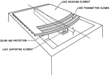
Rule 9: Load-supporting elernents, such as beams, girders, and joists, yield higlrcr fi,re end.urances when subjected tn fi.re endurance tests as parts of floor, roof, or ceiling assembli.es than tlrcy would when tested separately.
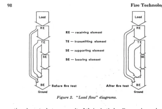
Before being able to prove the validity of this rule it is necessary to define the meaning of a few terms. Figure 1 is a diagrammatic picture of a corrmon floor construction. From the point of view of their role in trans-ferring the load to some vertical bearing construction (wall or column), the elements of this floor can be divided into three groups. The upper layer can be termed the "load-receiving" element. This layer is supported at short spans, therefore it is generaily a light construction. The components of the second layer can be called "load-transmitting" elements. As they are bridging somewhat larger spans, they usually contain some steel rein-forcement. The components that span the whole distance between two walls or columns can be termed "load-supporting" elements. These are either entirely of steel (trusses, girders, beams, joists), or are heavily rein-forced with steel. Finally, the walls or columns to which all the load im-posed on the floor is last transferred, can be termed "Ioad-bearing" ele-ments. It may be noted that very often a single layer plays the part of both the "load-receiving" and "load-transmitting" elements. The illus-tration at left in Figure 2, shows how, under the conditions contemplated by the design, the various elements contribute to transferring the load to the ground.
During the fire test the supporting elements are, as a rule, under the most adverse temlrerature conditions, and since they are spanning the largest distances, their deflection becomes significant at a stage when the strength of the transmitting and receiving elements is hardly affected by the heat. These elements will, of course, follow the deflection of the
sup-97
Fire Technology
RE - receiving element TE - tronsnitling elemenf SE - supporting element BE - beoring elemenl
Before Cre tect After fire tert
Figure 2. "Load. flow" diagrans.
porting elements, but as a result of their elastic bending, an increasingly larger portion of the load will be switched directly to the bearing elements
(walls, columns). Thus the load carried by the supporting elements will gradually decrease. The illustration at right in Figure 2 strows how the "load flow diagram" may appear toward the end of the fire test.
When load-supporting elements are tested separately, the imposed load is constant and equal to the design load throughout the test. Under zuch circumstances they carmot yield higher fire endurance than they do when tested as parts of a floor, roof, or ceiling assembly.
Rule 10: TIn laad.-supporting elemcnts (beatns, girdctr, joists, etc.) of a flmr, roof, or ceiLing assenbly can be replocd, by xrch othcr lnod,-supporting el.ements which, wlen tcstcd sepmratcly, yicldd, fi.re end,uru.nres rct Iss tlnn tlwt of tJrc assembly.
The validity of this rule rests on Rule 9. A beam or girder, if capable of yielding a certain performance when tested separately, will obviously yreld an equally good or better performance when it foms a part of a floor, roof, or ceiling assembly. It must be emphasized that the supporting ele-ment of one assembly must not be replaced by the supporting eleele-ment of another assembly if the performance of this latter element is not Inown from a separate (beam) test. Ilecause of the load-reducing effect of the receiving and transmitting elements, from the result of a test performed on an assembly, the trlerformance of the supporting element (beam, etc.) alone cannot be evaluated by simple arithmetic. This rule clearly indicates the advantage of performing fire tests on supporting elements separately and proves the validity of the concept that the results ane more widely app[-cable if smaller units rather than complex assemblies are subjected to fre tests.
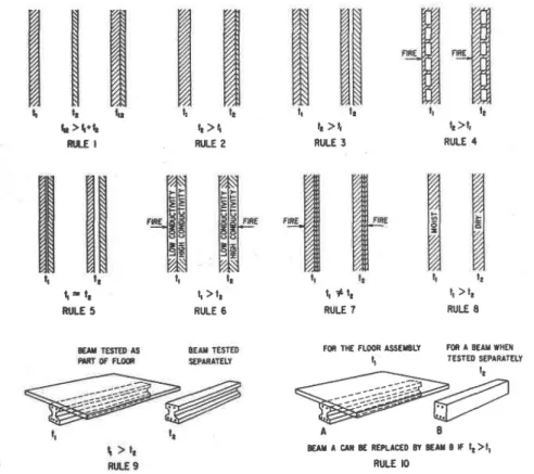
Fire Endurance Rating Rules 99 Figpre 3 is a diagrammatic illustration of the rules discussed in this paper- Although these rules do not eliminate the need for accurate and e}aborate design methods, they may give some assistance in solving many problems encountered in everyday practice.
l 1 t r t r h t h l t h > t . t t > i Rtl.E I RX-E 2 t + l r RULE ? lr lr t ) l r RULE 6
FM THE FLOOR ISSEIELY FOR A EEAX WHE}I tI TESTED SEPARATELY
@#2
A B bErr r crf, l€ REPLTGED 81 8€lr I F lr>ll Ru-E tO It >tt RULE 3 llFigure 3. Diagrammatic illustratinn of ten rul'es.
I : f,re enduronce
A number of examples that show how the rules can be applied to prac-tical cases follow:
A P P L I C A T I O N O F T H E R U L E S
Exan6lr.o 1: A contractor would like to use a partition consisting of a 3Y+-tn.-thick }ayer of red clay brick, aLY+-in.'thick layer of plywood and a %-in. gypsum wallboard, at a location where 2-hr fire endurance is required.
Qw*inn: Is this assembly capable of providing 2-hr protection?
Answer: Yes. The fire endurance of a 3%-in.-thick brick wall is approxi-mately 80 min. In small-scale experiments the fire endurance of a Ll('-in-' thick plywood was found to be 30 min, and that of a zz6-in- gypsum wall-board 13 min. According to Rule L, the fire endurance of the assembly must be larger than 80+30+13:123 min.
Exalgtr,p 2: A manufacturer of roof slabs would like to obtain experi-mental evidence that his products are capable of yielding 2-hr fire
en-lr lr t - l r M'LE 5 lr lr l. >tt RULE 4 lr lr tt >lr RULE 8
100 Fire Technology durance. According to a rigorous interpretation of ASTM E119,* how-ever, only roof assemblies, including the roof slabs as well as the cover and the supporting elements, can'be subjected to fre tests, and therefore a fire endurance classification cannot be issued for the slabs separately. The manufacturrer thinks, however, that his slabs will yield 2-hr fire endurance even without the cover, and any beam of at least 2-hr frc enduranoe may serve as satisfactory support. Thus, he believes that by prescribing a par-ticular cover and supporting system to be used with the slabs, the sale of his product will sufrer.
Qu.estion: Is it possible for the rnanufacturer to obtain classifcation for the slabs separately?
Arwwer: Yes. According to Rule 10 it is not contrary to comrmon sense to iest and classify roofs and supporting elements separately. Further-more, according to Rule 2, if the roof slabs actually yield a Z-hr fire en-duran@, the endurance of an assembly including the slabs cannot be less than 2 hrs either. The recommended procedure is to assemble the roof slabs on any oonvenient supporting system (not regarded as part of the specimen) and to subject them to a load which, besides the usually re-quired superimposed load, includes some allowance for the weight of the
cover.
Exervrpr,p 3: The fire endurance of a floor construction containing simple steel floor units was found to be 2 hrs and 40 rnin.
Question: Is there any hope that by replacing the simple floor units by cellular units the fire enduranoe can be increased to 3 hrs?
Ansuw: According to Rule 3 this replacement will favorably affect the performanee of the construction, but there is no simple way of estimat-ing the actual gain in fire endurance.
Exenrpr,n 4: A steel-joisted floor and ceiling assembly is known to have yielded a fre endurance of I hr and 35 min. At a certain location 2-hr endurance is required.
Questinn: What is the most economical way of increasing its firc endur-ance by at least 25 min?
Answer: A thorough examination of the drawings would be necessar5r. Slightly increasing the thickness of the ceiling plaster is always very effective. In this way there will be a twofold gain in fire endurance:
(i) a gain due to the greater thickness of plaster, and
(ii) a gain due to shifting the air gap farther from the exposed sur-face (Rule 4).
Exeupr,n 5: The fire endurance of a particular brick cavity wall con-sisting of two 3%-rn.-thick layers separated by a 2-in. air gap, is 4 hrc 40 min.
*The text of ASTM 8119 is similar to that of NFPA No. 251. Standard Methods of Fire Tests of Building Construction and Materials
Fire Endurance Rating Rules l0l Questian: Can the fire endurance of the wall be extended to 5 hrs by
in-creasing the thickness of the air gap to 4 in? Answer: No, by virtue of Rule 5.
Exeupr-n 6: In order to increase the insulating value of its precast roof slabs, a company has decided to make the slabs from two Iayers of different concretes. The lower half of the slabs, where the strength of the concrete is immaterial (since all the tensile load is carried by the steel reinforcement), is now made from a concrete of low strength but good insulating value. For the upper layer, where the concrete is supposed'to carry the com-pressive load, the original high strength, high thermal conductivity con-cnete has been retained.
Question: How will the fire endurance of the slabs be affected.by the change?
Answer: The effect on the thermal fue endurance is beneficial for two neaftons:
- (i) the total resistance to heat flow of the new slabs has been in-creased due to the replacement of a layer of high therrnal conductivity by one of low conductivity, and
(ii) the layer of low conductivity is on the side to be exposed to fire, where it is more effectively utilized according to Rule 6. The change is also beneficial to resistance of the slabs against collapse. The layer of low thermal conductivity provides a better protection for the steel rein-forcement, therefore the time of attaining the temperature at which the creep of steel becomes sigrrificant will be extended.
Ex,trrlpr.n 7: The fire endurance of an exterior wall consisting of a TYa-tn.lrayer of brick and a S%-tn.Iayer of sandstone is known. The wall was tested with the brick layer exposed to the fre.
Que*inn: Can the result be applied to the case when the sandstone is to be exposed to fue? :
Answer: No, by virtue of Rule 7. From Rule 6 it is evident that the con-struction will yield a lower fire endurance when tested from the direction of sandstone. (The thermal conductivity of sandstone is higher than that of the brick.)
Exaupr-p 8: A floor construction with concrete on steel floor units was tested in 1956 and was found to give 3 hrs and 18 min fire endurance. The test report reveals that the age of the specimen was 35 days on the day of the test. There is no information available concerning the moisture con-tent of the concrete slab.
Questian: Would the fire endurance of this construction be higher or lower if the tegt were repeated with the observance of the 1958 revision of ASTM 8119?
102 Fire Technology construction shall not be tested until the dampest section of the
as-sembly attains a 70 per cent relative humidity. It is the experience of
this laboratory that this humidily level cannot be attained in 35 days. It is also knownt that the sorption curve of concretes is very steep in the 80 to 100 per cent relative humidity range; in other words, above 8O per cent a srnnll change in relative humidity rnay mean a signfficant dif-ference in the amount of adsorbed moisture, and thus, in accordance with Rule 8, a significant difference in the fire endurance.
Ex^lupr,n 9: In a test of a floor assembly the deck failed thermally at
2 hrs and 21min. The submitter asked the testing authorities to continue
the test to see whether the beam would be capable of sustaining the ap-plied load for a 3-br period. The construction collapsed at 3 hrs and 15 rnin.
Question: Can the beam be qualified as one of 3-hr fire endurance? Answer: No. According to Rule 9 the beam was not tested under the most adverse cpnditions. It is possible that in combination with another deck, which exhibits less rigidity and contributes in a lesser degree to supporting the load, the same beam will yield a considerably poorer fre endurance. It is obvious from Rule 10 that if a beam is intended to be used in conjunction with a variety of floor or roof conshuctions, the best policy is to subject it to a separate fre test.
R E F E R E N C E S
-_ I "Temperature Distribution in Homogeneous Slabs During Fire Test," T. Z.
lt_aqqqtly,_ Transactians, Eng. Inst. of Cinada, Vol. 6, No. 8-6- (Oct. 1963). (Paper No. EIC-63-Mech 6.)
"'A Tleatise on Theoretical Fire Endurance Rating," T. Z. Harmathy, ASTM Spe-cial Technical Publication No. 301, 1961, p. 10.
3 "Effect of Moisture on the Fire Endurance of Buildi g Elements,".T. Z. Harmathy, ASTM Special Technical Publication No. 385, 1964, ChLicago.
I Discussion of "The Fire Resistance of Prestressed Concrete Beams," by L- A. Ashton
glt+ q. C-._C. Bate, C-. W. Shorter and T. Z. Harmathy, Proceedings,'In;t- Ciuil Engrs.,
Vol.20, No. 313, 1961.
6 "Fall,acies in the Cunent Per Cent of Total Absorption Method for Detenmining and Linniting the Moisture Content of Concrete Blocli," C. A. Menzelr BulLefin 84; Research Department, Portland Cement Association, Chicago, 1g57.