Publisher’s version / Version de l'éditeur:
Vous avez des questions? Nous pouvons vous aider. Pour communiquer directement avec un auteur, consultez la première page de la revue dans laquelle son article a été publié afin de trouver ses coordonnées. Si vous n’arrivez pas à les repérer, communiquez avec nous à [email protected].
Questions? Contact the NRC Publications Archive team at
[email protected]. If you wish to email the authors directly, please see the first page of the publication for their contact information.
https://publications-cnrc.canada.ca/fra/droits
L’accès à ce site Web et l’utilisation de son contenu sont assujettis aux conditions présentées dans le site LISEZ CES CONDITIONS ATTENTIVEMENT AVANT D’UTILISER CE SITE WEB.
Technical Translation (National Research Council of Canada), 1973
READ THESE TERMS AND CONDITIONS CAREFULLY BEFORE USING THIS WEBSITE. https://nrc-publications.canada.ca/eng/copyright
NRC Publications Archive Record / Notice des Archives des publications du CNRC : https://nrc-publications.canada.ca/eng/view/object/?id=c1f035a2-0906-4f90-a187-47ceba6c5d28 https://publications-cnrc.canada.ca/fra/voir/objet/?id=c1f035a2-0906-4f90-a187-47ceba6c5d28
NRC Publications Archive
Archives des publications du CNRC
For the publisher’s version, please access the DOI link below./ Pour consulter la version de l’éditeur, utilisez le lien DOI ci-dessous.
https://doi.org/10.4224/20337897
Access and use of this website and the material on it are subject to the Terms and Conditions set forth at
Instructions for determining ice loads on river structures
r
j.L"': i ' \ , NRC GIセ TT· 1663スjセ
i '"'
db / {,
セ ,,"-z,NATIONAL RESEARCH COUNCIL OF CANADA
TECHNICAL TRANSLATION 1663
INSTRUCTIONS FOR DETERMINING
ICE
LOADS
ON RIVER STRUCTURES
<SN 76-66>
NRC TT·1663
STATE COMMITTEE OF THE COUNCIL OF MINISTERS (USSR) FOR CONSTRUCTION (GOSSTROI, USSR)
PUBL.ISHER
IZOATEL'STVO L1TERATURY PO STROITEL'STVU MOSCOW, 1967. 19P.
TRANSLATED BY
G. BELKOV
THIS IS THE TWO HUNDRED AND TWELFTH OF THE SERIES OF TRANSLATIONS
PREPARED FOR THE DIVISION OF BUILDING RESEARCH
OTTAWA 1973
PREFACE
Because of their corresponding geographical positions, Russia and Canada share similar problems concerning the forces that ice can exert on
structures. These problems have received considerable attention from
Russian scientists and engineers. Their state of knowledge concerning them
has reached the point where it has been possible to formulate quite detailed instructions for the design of. structures that must stand up to the action of ice.
Knowledge and experience in Canada has only now reached the point where
it is possible to give consideration to the writing of such guidelines. It
was thought that it would be useful to have the most recent Russian Code of Practice concerning ice forces available for study and comparison when
this task in undertaken. The Division of Building Research of the National
Research Council is pleased, therefore, to be able to publish this document
in the NRC Technical Translation series. It must be emphasized, however,
that the investigations upon which the Russian Code is based are not readily available for evaluation, and so it is not possible to give a judgement as to
its validity for Canadian conditions. This document should only be considered
as an additional source of experience to be taken into account in the form-ulation of Canadian guidelines.
The Division of Building Research wishes to express its appreciation to Mr. G. Belkov, Translations Section, National Science Library, for the
preparation of this translation, and to Dr. L. W. Gold of this Division who checked the translation.
Ottawa July 1973
N. B. Hutcheon Director
Title:
Publisher:
Translator:
NATIONAL RESEARCH COUNCIL OF CANADA Technical Translation 1663
Instructions for determining ice loads on river structures (SN 76-66)
(Ukazaniya po opredeleniyu ledovykh nagruzok na rechnye
sooruzheniya (SN 76-66))
State Committee of the Council of Ministers (USSR) for
Construction (Gosstroi, USSR)
(Gosudarstvennyi komitet Soveta Ministrov SSSR po delam
stroite1'stva (Gosstroi SSSR))
Izdatel'stvo Literatury po Stroite1'stvu. Moscow, 1967. 19p.
'.
The "Instructions for Determining Ice Loads on River Structures" (Building Standard 76-66) were for-mulated by the B. E. Vedeneev All Union Research Institute of Hydrological Engineering, Ministry of Power and Elec-trification, USSR, in conjunction with the Novosibirsk Engineering Institute for Railroad Transport, Ministry of Communication; VNII VODGEO (All Union Research Institute for Water Supply, Hydrological Engineering Structures and Engineering Hydrogeology) Gosstroi, USSR; and the State Hydrological Institute, Main Administration of the
Hydrometeorological Service, Council of Ministers, USSR. When these "Instructions" come into force on October 1, 1967 they replace the "Technical specifications for deter-mining ice loads on river structures" (SN 76-59).
Editors - E. I. Dyshko (Gosstroi, USSR) and V. I. Sinotin (VNIIG) (All Union Research Institute for Engineering Hydrology)
Table of Contents
1. Terms of Reference 5
2.. Dynamic Loads 6
Bridge Piers with Vertical Leading Edges ..•..•...•... 6
Bridge Piers with Sloping Leading Edges ...•....•.• 7
Vertical Walls 7
Sloping Surfaces 8
The Action Of Drifting Ice Floes on Piers in a Reservoir. 8
Dynamic Loads Resulting from Ice Jams •..••••.•... 9
Friction Effects of Ice Floes on the Surface of Structures 10
3. Static Loads 10
Loads Generated dオイゥョァセィ・イュ。ャ Expansion of a Continuous
Ice Cover 10
Vertical walls .••.•...•... 10
Bridge piers 12
Loads Resulting from Pile-up of an Ice field ...•••••.... 12
Loads Resulting from an Ice Jam 13
The Effect of an Ice Cover Frozen Fast to a Structure ..• 14
Slopes and walls 14
Piles and Pile Clusters .••...•.•...•...•..• 16
Tables (\ . . . . 17
State Committee on Construction Council of Ministers USSR (Gosstroi, USSR)
Building Standards INSTRUCTIONS FOR DETERMINING ICE LOADS ON RIVER STRUCTURES
1. TERMS OF REFERENCE
SN 76-66 Replaces SN 76-59
1.1. These Instructions cover the design of hydraulic structures and bridge piers.
Notes: 1. These Instructions also cover the design of structures on
lakes and reservoirs.
2. In designing hydraulic structures of Class I magnitude and bridges
where there are difficult ice conditions, ice loads determined by the cur-rent Instructions should be modified only after detailed field observations and laboratory investigations.
1.2. In designing hydraulic structures on rivers and bridges, the following ice loads must be considered:
a) The dynamic load from impact of individual floating ice floes;
b) Load from ice jams (dynamic);
c) Load due to thermal expansion of a continuous ice cover (static);
d) Load from an ice field due to the action of wind and current (static);
e) Load induced by ice frozen fast to the structure during fluctuations
in water level (static);
f) Load resulting from the friction of floating ice against the surface
of the structure (dynamic).
Notes: 1. A particular type of ice load need not be taken into
con-sideration if engineering and economic calculations indicate that special measures can be installed to prevent the action of these loads on a structure.
2. In the current Instructions a definition is given for the standard
strength limits and load values for ice. The design formulae for determining
Introduced by the Ministry of Power and Electrification, USSR
Confirmed by the State Committee on Construction, Council of Ministers, USSR, 30 December 1966
Instructions come into force 1 October 1967
-l)-ice loads take into consideration an assumed overload coefficient of 1.1
3. In designing hydraulic structures by the failure load method the
design ice load is taken to be equal to its standard value.
2. DYNAMIC LOADS
Bridge Piers with Vertical Leading Edges'
*
2.1. The load PI' in tons on a pier in the direction of its longitudinal
axis resulting from an ice field moving past the pier is determined by the formula
(1)
where m is the coefficient for the shape of the pier, taken to be:
a) 0.9 for a semi-circular leading edge;
b) for a triangular leading edge of a pier (regardless of the radius of the
leading edge) the value of m depends on the apex angle, 2€, as shown in Table I.
Note: The value for an angle of 1800 is given in the table only for
finding the value of m by interpolation when 1200 < 2E: < 1800;
A is the climatic coefficient taken from Table II;
Rp is the crushing strength of ice, assumed to be (in the absence
of experimental data) 75 T/m2 , and at the time of maximum water
level at breakup, 45 T/m2 ;
b is the width of the bridge pier at the water level occuring at
breakup, in meters;
h is the calculated thickness of ice in meters, taken to be 0.8 of the thickest ice during the winter with a probability of 1% of
being exceeded (99% confidence level). When there is insufficient
original data it is recommended that regional formulae be used for determining h.
*
All loads in this Standard have units of metric tons, abbreviated T....
-7-Bridge Piers with Sloping Leading Edges
2.2.
The horizontal component of the ice load, P2Y' in tons, acting on apier in the direction of its axis is computed by the formula
•
(2)
The vertical component P2v, in tons, is determined by the formula(3)
In formulae (2) and (3) R
i, the failure strength of ice in bending in
T/m2, is taken to be 0.5 R ;
S
is the angle between the cutting edge of thep
pier and the horizontal, in degrees.
o
Note: When the angle of inclination S is greater than 75 the load
P2Y should be determined by formula (1).
2.3. If the horizontal load component determined by formula (2) exceeds
the load determined by formula (1), the latter is used for calculation.
Vertical Walls
2.4.
Load P3 , in tons on vertical walls due to the impact of single icefloes is determined as follows:
a) When the ice floes are moving in a direction close to normal to
o
the face of the structure Hセ
=
80 - 90 ) use the formula(4)
b) When the ice floe is moving at an angle to the face of the structure
of セ < 800 the normal load component is determined by the formula
(5)
..
The greatest possible load per unit length on a vertical wall ofextended structures (dams, dikes, etc.) in T/m acting perpendicular to the face should not be taken as being greater than that determined by the formula
-8-where Rc is the compressive strength of ice (without taking into consideration local crushing), taken to be 45 T/m2 ;
k is a coefficient expressing the irregularity in the contact between the ice surface and structure which is taken to be 0.6 and 0.8 for the initial stage and high water stage of runoff, respectively. For the notations vz' セ and j, see 2.6.
Sloping Surfaces
2.5. The horizontal component of ice load on a sloping surface P4 in T/m,
due to impact of an ice field, is determined by the formula
(7)
where A' is a coefficient taken from Table III depending on ice thickness h. The vertical component of the ice load on a slope P 4V is determined by the formula
(8)
The Action of Drifting Ice Floes on Piers in a Reservoir
2.6. The load on a pier P
s •
in tons. in a direction along its major axis resulting from collision with a drifting ice floe is determined bv formula1
where j. a coefficient having the dimension sec T2/ m2 , depends on the obstacle the ice floe encounters. For a pier it is 0.43, and for
a wall 0.7;
vl is the calculated velocity of a drifting ice floe in m/sec which. depending on wind velocity, is Vz
=
0.02 w m/sec. but not greater than 0.6 m/sec. The calculated wind velocity. w. is based on meteorological data. and when these are deficient it is determinedfrom the area of the ice floe. セL using Table IV.
セ is the calculated area of ice floe in m2 taken from field observa-tions or by analogy with other structures. The calculated area
-9-should not be less than
rl.
=
1. 75 '[2.mln '
'[ is the greatest span of the bridge between piers or the size of
the ice discharge opening in meters;
Rp is the crushing strength of ice taken to be 45 T/m2•
The calculated value of load resulting from a drifting ice floe in a reservoir is taken to be the least of the values calculated by formulae (9) and (1), where the Rp value recommended above, and a climatic factor, A, of
1 are used in formula (I),
2.7. If the direction of movement of the ice floe is different by 10 or
more degrees from the direction of the axis of the support, the ice load on the vertical face of the support P6 is determined by the formula
(10)
where 0 is the angle between the direction of movement of the ice floe and
the axis of the pier.
Dynamic Loads Resulting from Ice Jams
2.8. The load resulting from ice jams (during fall and winter) acting
against a pier in a direction parallel to its longitudinal axis is determined by the formula
(11)
where m is a coefficient depending on the shape of the pier, given in
Table 1.
b is the width of the pier in meters;
Tp is the failure strength of the ice mass taken to be 12 T/m2 (in shear);
h3 is the estimated thickness of the ice mass based on an analysis of
the ice-thermal regime of that portion of the river, but not greater than 0.8 of the average depth of water during the ice jamming
-10-2.9. The influence of ice jams on structures (during spring breakup) is
estimated by analyzing field observations of the ice conditions at the
proposed site. It is recommended that the structure be designed so as to
avoid the possibility of an ice jam forming at the structure (increasing the span of bridges, the size of ice removal openings, etc.).
Friction Effects of Ice Floes on the Surface of Structures
2.10. The maximum longitudinal load P
a
in Tim resulting from the movementof an ice floe along a vertical structure is determined by the formula
•
(12)
where P 3v ffi the maximum possible ice load perpendicular to the front of the
structure, determined by formula (6);
f is the coefficient of ice friction against the surface of a structure,
for concrete taken to be 0.11.
Note: In designing structures special measures should be developed
to decrease the friction of ice against structures (providing a smooth sur-face, increasing the strength of the surface layer of concrete, prOViding smooth facings on concrete surfaces, etc).
3. STATIC LOADS
Loads Generated During Thermal Expansion of a Continuous Ice Cover Vertical walls
3.1. The static load Pt, in Tim, per unit of length of contact between the
ice and a structure resulting from thermal expansion of the ice cover is determined by the formula
. (13)
where R
o
is the elastic limit of ice taken to be 5 T/m 2;h is the thickness of the ice cover in m taken to be equal to the
I
•
-11-1
is the coefficient of linear expansion of ice equal to 5.5 . 10-5
°C
セ is the rate of increase in air temperature in degrees per hour
during a time period of T in hours. During regular observations
carried out four times a day the highest value of .t9>for any
six-hour period of the day is taken;
セ is the coefficient of ice viscosity in T . hr/m2 determined as
follows:
a) for t セ -200C use formula
b) when t < -20 C use the formulao
f.l.
=
(3,3 - 1,85t) 104 ;(14)
(15)
o
t is the ice temperature in C determined by the formula
t
=
8110+
itt ,h·2 't'. (16)
e
is the initial air temperature in°c
from which the temperaturebegins to increase;
nO relative thickness of the ice cover taking into consideration the influence of snow and determined by the formula
h h
110
= - =
---.-:-:=--=----hn / a A. (17)
It+hcl
-
ae+-
fibh n is the reduced thickness of ice cover;
h c is the least thickness of ice cover in m, corresponding to the period of calculation and determined by direct observations of the ice cover for the given section of the river.
When there are no direct observations snow cover is not taken into ac-count;
a is the thermal diffusivity of ice equal to 0.0041 m2/hr;
a c is the thermal diffusivity of snow equal to 0.002 m2/hr;
•
A is the thermal conductivity of ice equal to 2 kca1/m . hr
.
degree;ab is the coefficient of heat transfer from air to the snow-ice surface
in kca1/m2 • hr, equal to:
a) in the presence of snow, 20/w
+
0.3;
-12-b) in the absence of snow, S/w
+
0.3;w is the mean peak velocity of wind in m/sec corresponding to the
period of the largest calculated value of the rate of increase of
air temperature セ
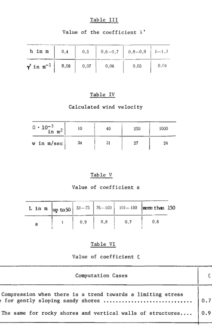
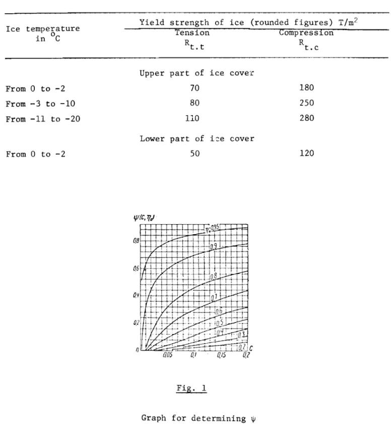
セLセ are coefficients whose values are determined from Figures 1 and
aT h
2 respectively depending on the value of C セ kT and nO セ --;
hiT hiT
S is the coefficient depending on the extent of ice cover determined
from Table V.
Bridge Pie.::"s
3.2. The static load Po' in tons, on a pier when an ice-free area is
main-tained in the spans between them is determined by the formula
(18)
where
Z
is the width of span in m;b is the width of support in m;
PT is the static load determined by equation (13).
Loads Resulting from Pile-up of an Ice Field
3.3. The horizontal load PH' in tons, resulting from a wind and water driven
pile-up of an ice field against a structure is determined by the formula
(19)
where PI is the force caused by current drag on the lower surface of the ice
field per unit area, in T/m2;
P2 is the force of hydrodynamic pressure on the edge of the ice field
caused by flow, per unit edge surface area, in T/m2;
P3 is the horizontal component of the force of gravity on the ice field
where there is a slope of the free flow surface, per unit surface
area of the ice field, in T/m2 ;
P4 is the force resulting from the air drag against the upper surface
of the ice field, per unit surface area, in T/m2 ;
st is the estimated area of the ice field in m2 •
-13-The values of PI' P2, P3' P4 in T/m2 are taken to be:
•
Pa= k3hi;(20)
(21) (22)
(23)
where k I is a coefficient having the dimensions of T . sec2/m4 and taken to
be 5 • 10-4 for a continuous ice field and 20 . 10-4 for ice jams;
k2 is a coefficient having the dimension of T
.
sec 2/m4 and taken tobe 5
.
10-2 ;k3 is a coefficient having the dimension of T/m3 taken to be 0.92;
k4 is a coefficient having the dimension of T
.
sec2/m4 and taken tobe 2 . 10-6 ;
v is the flow rate of water under the ice in m/sec during the periods
of ice accummu1ation, with a probability of 1% of being exceeded;
w is the velocity of wind in m/sec during the period of breakup with
a probability of 1% of being exceeded;
h is the thickness of an ice field in m taken from section 2.1.;
L is the mean length of ice field in the the direction of the flow
taken from field observations but not to exceed three times the width, in meters;
i is the water surface slope.
Loads Resulting from an Ice Jam
3.4.
The load Pz' in tons, against a structure during the accummu1ation ofice (perpendicular to the ice front) is determined by the formula
(24)
•
where Lz is the length of the ice jam from which pressure is transmitted against the structure, taken to be 1! times the width of the river at the structure, in meters;
-14-B is the length of the structure in meters;
PI' P2' P3' P4 are pressure components determined from section 3.3. In making these calculations the thickness of the ice jam is
taken from section 2.8; in computing the rate of flow consideration is given to constriction of the river bed by the ice jam of the given thickness; the slopes at the location where the ice jam is formed are determined from observations or by analogy with other situations.
3.5. The load exerted by an ice jam on unit length of structure parallel to
the direction of flow (as well as against the shores) Pb, in Tim, is
deter-mined by the formula
•
(25)
where セ is the coefficient of lateral pressure taken from Table VI.
The Effect of an Ice Cover Frozen Fast to a Structure Slopes and walls
3.6. A bending moment may be generated on a structure or on individual
parts of it when an ice cover frozen to it moves vertically due to variations
in water level. This moment Mx in ton-m, acting in the vertical plane
perpendicular to the face of the structure is determined by the formula
Mx
=
Rd.t • Rd.c.Rd.t.
+
Rd.c. (26)where B is the calculated length of the face of the structure or individual
parts of it at the water line, in meters;
hk is the calculated thickness of the ice cover in meters, taken to be equal to the thickness of the crystalline layer established by
observation for the given case; for preliminary calculations of
the thickness of the crystalline layer it can be assumed to be
within the limits of hk
=
0.8 to 0.9 h, where h, the thickness of theice cover beyond the shore-influenced zone, is taken to be equal to the thickness of the ice, with a 1% probability of being exceeded, for the period during which the water level fluctuates;
t
Rd.t,
-15-Rd are the design stress of crystalline ice in T/m2 in tension
. c
and compression respectively, determined with the time-dependent
ice stress coefficient kp セ 0.85 by formulae (27) and (28); if
the value of kp > 0.85, then the design stress is taken to be
Rt t and R. " t ,c ,
2
Rt.r ,
kp is the time-dependent ice stress coefficient associated with relaxation under tension or compression.
R
kp = セR = exp (-tin) (notation given in section 3.7);
t
Rt are the yield strength of crystalline ice in tension and
.c
compression taken either from Table
VII
or from experimental data,in T/m2 ;
kE is the coefficient of modulus of elasticity taken as 1 when
kp セ 0.85 and 2 when kp > 0.85.
3.7. Design values of the time-dependent stress associated with relaxation during
deformation of ice are calculated by the formulae
Rd.t
=
Rt. t exp (-tin) Rd•c=
Rt .c exp(-,In)
(27) (28) II•
where, is the time in hours during which there is deformation of the ice
cover due to rise or fall in water level by an amount equal to the thickness of the ice;
n is a parameter characterizing the rate of relaxation; n
=
f
103 ;セ is a coefficient representing the viscosity of ice as determined in
section 3.1 for an ice temperature corresponding to the temperature
of the upper part of the ice cover, in T . hr/m2 ;
E is the modulus of elasticity of the ice which in the absence of
experimental data is taken to be 4 • 10 5 T/m2.
Notes: 1. The temperature of the upper part of the ice cover used
in denoting the design yield point of ice and in computing the viscosity coefficient is taken to be the mean temperature of the lower, diurnal, below-freeZing air temperatures during the period when the water level changes.
..,
• - . . . セ L __セ ...;:..o
-16-of snow on ice temperature, according to section 3.1, is considered in regions where there is a stable snow cover during the period when there are changes in water level.
2. During deformation of the ice cover caused by an increase in water
level the temperature of the upper part of the ice is considered to be
within the range of 0 to -2oC.
3. The temperature of the lower part of the ice cover is in all cases
considered to be OOC. "
4. In calculations for the spring low-water period before melting
starts, the thickness of the ice cover,h, and the mean below-freezing diurnal air temperatures are obtained from the mean annual values for the period of
30 days before the beginning of continuous melting of the ice.
Piles and Pile Clusters
3.8 The vertical load Pc' in T, which is transmitted by an adhering ice
cover to individual piles and pile clusters when the water level increases is determined by the formula
p ]⦅ォ」セ c SOh' I n -d (29) where k c is taken to be 300 T/m 2;
h the thickness of the ice cover, is taken to be the maximum thickness
of ice with a
1%
probability of being exceeded, in meters;d is the diameter of the pile or piles cluster in meters; with a
rectangular cluster with sides x and y the value of d is taken to be
&y.
Notes: 1. Formula (29) is applicable when there is a continuous ice
cover.
2. Here we consider individual piles and pile clusters surrounded by
a continuous ice cover extending over a radius of not less than 20 h.
3. Formula (29) may be applied for a pile cluster in which the distance
between individual piles is not more than 1 m.
28 -17-Table I Value of coefficient m 1200 m 0,54 0,59 0,64 Table I I 0,69 0,77
•
No. of region I 2 3 4 5 6 Climatic coefficient A ClimaticBoundaries of region coefficient
A
South of the line Talin 1.
Minsk Khar'kov Astrakhan Nukus
-Alma-Ata 0.75
South of the line
Vyborg - Smolensk - 2.
Kamyshin Aktyubinsk
-Balkhash 1
South of the line Arkhangel'sk Kirov -Ufa - Kustanai
Karaganda -
Ust'-Kamenogorsk 1.25
South of the line Vorkuta Khanty
Mansiisk Krasnoyarsk UlanUde
-Nikolaevsk-na-Amure 1. 75
South of the line Dikson Noril'sk Vodaibo
-Okhotsk 2
North of the line Dikson - Noril'sk
Vodaibo - Okhotsk 2.25
Notes
For regions No. 2-5 the lower boundary is also the boundary of the foregoing region.
The climatic coef-ficient can be based on field observations of conditions at spring breakup, but for breakup with negative air
temp-o
eratures
«
0 C) it
-18-Table III
Value of the coefficient A'
h in m 0,4 0,5 0,6-0,7 0,8--0,9 1-1,3
y'in m-1 0,08 0,07 0,06 0,05 0,04
It
Table IV
Calculated wind velocity
セ
• 10-3I
in m2 w in m/secl 10 34 40 31 Table V 250 27 1000 24 Value of coefficient s L in m slup
tosa
I
51-751
I
0,9 176-100I
I
0,8I
Table VI 101-150 0,7IIIDre
thal. 150I
0,6 Value of coefficient セ Computation Cases セCompression when there is a trend towards a limiting stress
state for gently sloping sandy shores •••....••••.••.•.•...••••.• 0.7
-19-Table VII
Yield strength of crystalline ice when the force is acting perpendicular to the axis
of the crystals
Yield strength of ice (rounded figures) T/m2
Ice temperature Tension Compression
in
°c
Rt. t Rtoc
Upper part of ice cover
From 0 to -2 70 180
From -3 to -10 80 250
From -11 to -20 110 280
Lower part of ゥセ・ cover
From 0 to -2 50 120 ::r:: t QBf-H---i--+y--J,.1'TfH+-+-+-+-+-+- H --+-l I Fig. 1
-20-C 1 0.'1 0.3 0,7 01
r-T
s:
-
セ...
I.--'olg-Qセ
-
-- 17セ 1_.... I -- -..-
....
0,8k.l
V 17[/
I..-...
I I -セ L V 07-
セ N⦅セ1--17l.--'
...
-JIt
t7
f7
l.-. -v
06 _1--10-セ17
r>...
"nlS(/ltC, TJ.) l..-II I 17 v [;;-1£p >-セGoセ
' セV I I... l..-I.--'lo- u.!
II, I I L.- セ 1/
.
f-- !-- 0.15 l -'IT7fJ I 1/ .-ntv
1/ i / Ql セ 01b-)£ :T I:J"1,1 l- I- 2.0 - I -1/r:!V '11セセ
V I OB .boo TI77 r> L-J - r III/h' 0 ODD? 000'1 000600080.0o
(1.7 0.9 08oe
0.5 0.4 fl,J 0.1 0.1 Fig. 2Graph for determining セ