A comprehensive multi-scale analytical modelling framework for
predicting the mechanical properties of strand-based composites
The MIT Faculty has made this article openly available.
Please share
how this access benefits you. Your story matters.
Citation
Malekmohammadi, Sardar, Navid Zobeiry, Thomas Gereke,
Benjamin Tressou, and Reza Vaziri. “A Comprehensive Multi-Scale
Analytical Modelling Framework for Predicting the Mechanical
Properties of Strand-Based Composites.” Wood Sci Technol 49, no. 1
(October 31, 2014): 59–81.
As Published
http://dx.doi.org/10.1007/s00226-014-0682-8
Publisher
Springer Berlin Heidelberg
Version
Author's final manuscript
Citable link
http://hdl.handle.net/1721.1/107176
Terms of Use
Article is made available in accordance with the publisher's
policy and may be subject to US copyright law. Please refer to the
publisher's site for terms of use.
1
A COMPREHENSIVE MULTI-SCALE ANALYTICAL MODELLING FRAMEWORK
FOR PREDICTING THE MECHANICAL PROPERTIES OF STRAND-BASED
COMPOSITES
S
ARDARM
ALEKMOHAMMADI1*,
N
AVIDZ
OBEIRY1,
T
HOMASG
EREKE2,
B
ENJAMINT
RESSOU3,
R
EZAV
AZIRI11
Composites Group, Departments of Civil Engineering and Materials Engineering, The University of British Columbia, 6250 Applied Science Lane, Vancouver, B.C., Canada V6T1Z4
2
Institute of Textile Machinery and High Performance Material Technology, Technische Universität Dresden, 01062 Dresden, Germany
3
Département Physique et Mécanique des Matériaux, Institut P', CNRS - Université de Poitiers - ENSMA - UPR 3346, 1, Avenue Clément Ader, BP 40109, F86961 Futuroscope - Chasseneuil Cedex, France
*
Corresponding author, currently in Department of Materials Science and Engineering, MIT, 77 Massachusetts Ave, Cambridge, MA, 02139, USA
email: [email protected]
Abstract
A multi-scale modelling framework was developed for predicting the mechanical properties of strand-based wood composites. This framework is based on closed-form analytical models at three different resolution levels; micro-, meso- and macro-mechanical. A preprocessing step was performed to provide the input data for the three main modelling steps in this framework. Finite element based mechanical analyses were employed to validate the analytical models developed for the first two steps. The predictive capability of the entire framework was validated using a set of experimental data reported in literature. Although the methodology presented is general, it has specifically been applied here to predict an important structural property (modulus of elasticity, MOE) of a special strand-based wood composite product, namely Oriented Strand Board (OSB). The MOE predictions of OSB panels showed reasonable agreement with the available experimental data, thus providing confidence in the practical utility of this easy-to-use and efficient analytical modelling tool for predicting the properties of wood composites employed in structural members.
Introduction
Strand-based wood composites are being widely considered as the sustainable choice of materials for structural members of modern buildings. Given the wide variety of wood composite products that can result from the combination of wood strands and resins and the manufacturing routes used to produce them, it is desirable to have quantitative tools that can predict the mechanical response of the materials for the purpose of structural analysis and design. There are several parameters that may affect the structural response of strand-based wood
2
composites such as wood species properties, resin content, density profile, orientation of wood strands, layer assembly, etc. (Chen et al. 2008, Moses et al. 2003, Stuerzenbecher et al. 2010, Wong et al. 1999). Designing a wood composite product with suitable properties and at low costs requires a good understanding of the mechanics of these materials. It is also essential to have quantitative tools that can estimate the macroscopic behavior of wood composite products under specific loading conditions based on their manufacturing process and microstructural details. The presence of these tools would enable strand-based wood composite manufacturers to optimize their products taking into account the balance of performance and costs.
Several modelling approaches have been proposed in the literature to predict stiffness and strength of strand-based wood composites (Arwade et al. 2009, Barnes 2000, Benabou and Duchanois 2007, Moses et al. 2003, Shaler and Blankenhorn 1990, Stuerzenbecher et al. 2008). Among those, Shaler and Blankenhorn (1990) have considered the effect of flake geometry, flake orientation, density, resin content, and species. Arwade et al. (2009) proposed a stochastic model for Parallel Strand Lumber (PSL) beams. Although they have considered the variability in strand length, resin content and presence of voids have been neglected. Barnes (2000) proposed an integrated model for predicting the strength of oriented wood strand products. Although Barnes (2000) has included many processing parameters in his model, it requires a wide range of experimental data and empirical equations which may be very time-consuming and costly to obtain. Furthermore, the final model is only useful for a specific product. A two-step, fully numerical, multi-scale framework was previously developed by Gereke et al. (2012) for strand-based wood composites. The capability of this framework was examined for PSL. Although the strand orientation was considered by Gereke et al. (2012), the presence of voids, imperfect bonding between the strands and density variation throughout the beam were ignored. From a practical standpoint, in most strand-based composite products, strands are partially covered with resin and voids are present. Additionally, strands are compacted due to the manufacturing process. Therefore, in order to develop an accurate analytical tool, more realistic assumptions need to be adopted.
A comprehensive multi-scale model which employs mechanistic, physically-based equations can complement previous works in this area. Therefore, a micro-mechanical step has been added to the previously developed
framework. Using this step, strand compaction and density variation throughout the composite product were considered. Additionally, microstructural features such as voids, wax, fines content, etc., have been incorporated in the modelling approach. Unlike the previous multi-scale model presented in Gereke et al. (2012), all the calculations
3
in the current framework can be performed analytically. This would result in a reduction of effort to set up the problem and computational time required to solve it.
In the present approach, the effective mechanical properties of the material were obtained at the micro-, meso- and macro-scale sequentially. Analytical approaches presented in Gibson and Ashby (1999) and in Malekmohammadi et al. (2014) were employed to predict the material properties at the micro- and meso-scales, respectively. Numerical approaches (Gereke et al. 2011, 2012) were used to check the validity of the analytical equations and the assumptions made therein. The last step involving the macro-scale was performed analytically using the results obtained from the previous steps, together with the applied load and structural member’s geometry. Although the last step may need to be performed numerically (see Gereke et al. 2012)) for complex geometries, loading and boundary conditions, only an analytical approach is presented here for a simple structural application. By maintaining an all-analytical approach for the various steps involved, the significance of errors incurred at each step on the final predictions could be better investigated.
In order to validate the complete modelling framework, the modulus of elasticity of OSB panels with a range of through-thickness (i.e. cross-sectional) density profiles was predicted and compared with the experimental study conducted by Chen et al. (2010).
Materials and methods
Framework description and main assumptions
Fig. 1 illustrates the multi-scale analysis framework in its general form for predicting the MOE of OSB panels. In a pre-processing step, parameters such as strand density, resin thickness and resin area coverage were back-calculated from panel characteristics (e.g. overall density, species, resin content, etc.) based on the following assumptions:
• Panel can be divided into multiple layers (depending on the required accuracy) • Each layer consists of strands, resin, wax, fines, and voids
• Strand and resin volume fractions are constant within a layer but may vary from one layer to another, according to the Vertical Density Profile (VDP)
4
• Uncompacted wood strands have the same physical and mechanical properties as those of the neat wood (e.g. given in Wood Handbook (Forest Products Laboratory 1999))
• Fines have the same density as strands within each specific layer
• Resin and wax are incompressible while strands and fines are compressible • Strands are compressed in their radial direction (X2-direction in Fig. 2c)
• Resin thickness is uniform around a single strand in each layer
• Fines do not make any contribution to load transfer. Their presence only contributes to the density of the wood composite product.
Preprocessing step
Initially, and in order to provide inputs for other steps, a preprocessing step needed to be performed. In this step, the following parameters were determined for “each layer” first:
• Uncompacted strand density, s UC. Density of an uncompacted wood strand was calculated using the following equation given in the Wood Handbook (Forest Products Laboratory 1999):
1000 1
s UC SG MC (1)
where the specific gravity (SG) values for several neat strands are provided in the Wood Handbook (Forest Products Laboratory 1999). The moisture content (MC) of the strand was assumed to be equal to the moisture content of the panel for a specific layer of interest.
• Resin volume fraction, V . Assuming that the resin density, r r, is constant throughout the panel, the resin
volume fraction in each layer was estimated based on the panel resin content by weight, W , and the layer r
density, layer, taken from panel vertical density profile (see Fig. 1).
layer
r r
r
V W (2)
• Wax volume fraction, V . Assuming a constant value for wax density, the wax volume fraction in each w
layer was estimated based on the panel wax content by weight, W , and wax density, w w, as follows:
layer
w w
w
5
• Void volume fraction, V . The void volume fraction in each layer was assumed to be proportional to the v density of the layer, layer. In other words, voids shrink at the same rate as the panel densifies during the
manufacturing of the panel. The core layer in the center of the panel was chosen as a reference layer (zero compaction) with known void volume fraction, Vv core, and density, core, for this purpose. Therefore, as
the layer density changes through the panel thickness, void volume fraction in each layer varies accordingly:
core
v v core
layer
V V (4)
• Strand volume fraction, V , and fines volume fraction, s Vf. Assuming that fines have the same density as
the strand (i.e. s), in a given layer, their volume fraction was estimated as:
1 f f v w r s W V V V V W (5)
where Wf and W are the fines and strand weight fractions, respectively. Therefore, the strand volume s
fraction, V , can be written as: s
1
s v w f r
V V V V V (6)
• Compacted strand density, s. Having determined the strand volume fraction, V , the strand density in s
each layer (compacted strand) was determined using the following equation:
layer
s s
s
W
V (7)
• Compaction ratio, C , is the ratio which is a measure of strand compaction in each layer and is defined as: r s
r
s UC
C (8)
• Strand thickness, R . Strands are compressed in the direction normal to the panel (X2-direction in Fig. 2c).
Therefore, strand size varies through the thickness of the panel accordingly:
UC r
R R
6
• Resin thickness, t . Assuming the uniform coverage of strands by the resin, the resin thickness is constant r in all three directions. Therefore, Equation (6) may also be written in terms of the strand thickness, width, length (R, T, L) and the resin thickness, t , as: r
( )( )( ) s r r r RTL V R t T t L t (10)
• Assuming that the resin thickness is negligible compared to the strand length (tr L ), the above equation
may be simplified and solved for resin thickness, t : r
2 2 2 2 4 (1 ) 2 s s s s s r s T R V T R V V V Tt t V (11)
• Resin area coverage, R . This parameter is defined as the ratio of actual area covered with resin (partial a strand coverage) to the maximum available area to be covered by resin if there were only resin and strands in the panel (full strand coverage):
max ( )( ) ( )( ) r r r a r r r A T t R t R V A T t R t RT (12)
In deriving the above equation, it was assumed that fines act as voids and there is no bonding between the fines and the strands or between the fines and the resin.
Micro-mechanical step
Mechanical properties of strands in each layer (compacted strands) can be estimated from their constituents’ properties and microstructural features such as micro-cellular geometrical parameters. Researchers have used both numerical (Gereke et al. 2011, Guo and Gibson 1999, Qing and Mishnaevsky 2009) and analytical methods (Gibson and Ashby 1999, Hofstetter et al. 2005) for this purpose. The numerical approach and the analytical approach employed in this framework are presented below. Additionally, the validity of the analytical approach in predicting the elastic moduli of both normal (uncompacted) and compacted strands was investigated.
7 Numerical approach
Knowing the specific gravity (SG) of a given wood strand and the density of the solid cell wall material, cw,
at moisture content of 12 %, the micro-cellular geometrical parameters (lR,lT,t tR, ,T ) of earlywood and latewood
(see Fig. 2a for what these parameters signify) were computed using the following assumptions:
• Wood has a uniform, periodic cellular microstructure from which a unit cell of the material can be identified.
• The wood cellular microstructure is hexagonal and remains hexagonal (Fig. 2) during compaction. See Gereke et al. (2011) and Qing and Mishnaevsky (2009) for more details.
The cell wall was modelled as an elastic laminate consisting of four layers: S1, S2, S3 and a compound middle lamella, CML (Fig. 2b). The connection between the cell walls was realized with the CML, which homogenises the properties of the middle lamella and the primary wall in the model. The cell wall is a
fibre-reinforced composite with cellulose fibres (micro-fibrils) embedded in the natural polymer lignin. The orientation of the micro-fibrils influences the mechanical properties of the cell wall. The micro-fibril angle (MFA) varies in the dominating S2-layer between 10° and 30° depending on the species, the age and the source of the cell, earlywood or latewood (Dinwoodie 1975, Kollmann and Cote Jr 1968). The MFA is incorporated as the inclination of the local X1
material orientation of each secondary layer (S1, S2, and S3).
The microstructure of wood strands was idealized as a regular honeycomb structure consisting of hexagonal cells (Fig. 2). A three-dimensional representation of the microstructure was realized in an FE model of the unit cell. The dimensions of the air-filled core (lumen), l and R l (see Fig. 2a), and the thicknesses of the cell wall layers, T t , S1
2 S
t , t and S3 tCML(see Fig. 2b), represent the cellular geometry of the wood in the model. The angle defines the inclination of the radial cell wall (see Fig. 2a).
Once, the ratio of earlywood to latewood had been estimated, the property of a single strand was computed through a computational homogenization technique, wherein periodic boundary conditions were applied. This procedure was described in Gereke et al. (2012) and Michel et al. (1999). In wood composites where resin penetration into the wood cellular structure (lumen) is possible, an interface layer (wood with penetrated resin into the lumen) may also be considered. The properties of this interface layer can be estimated by assuming that the lumen is partially filled with resin.
8
It should be noted that due to the last assumption (hexagonal cellular microstructure), the accuracy of this model diminished at higher compaction levels. As the compaction level increases, the cellular structure of the strands may not be represented accurately by hexagonal cells.
Analytical approach
Gibson and Ashby (1999) proposed the following equations to predict the properties of different wood species based on their density:
2 s cw s L L cw E C E (13)
As an alternative to the numerical method, the above equation may be employed to predict the strand’s Young’s modulus in the longitudinal direction,
s L
E , of strand knowing the strand density, s, solid cell wall
density, cw, and cell wall axial Young’s modulus, ELcw. The coefficient C is a parameter which has been found to 2
be close to unity for most wood species (see Gibson and Ashby 1999). Other moduli were calculated based on the ratios of the strands’ Young’s modulus in the longitudinal direction to their value for a given species. These ratios can be found in the Wood Handbook (Forest Products Laboratory 1999). In the current framework, these ratios were assumed to remain constant during compaction.
Validation
In this section, predictions of both the numerical and analytical approaches for elastic moduli of normal wood strands are compared with reference data given in the Wood Handbook (Forest Products Laboratory 1999).The cell wall layers’ elastic and geometrical properties used for the numerical approach are listed in Table 1 and Table 2, respectively. The elastic properties listed in Table 1 were taken from Qing and Mishnaevsky (2009). Note that for the S1, S2 and S3 layers, constant MFA angles of 70°, 80° and 15° have been implemented within the local coordinate system in the finite element code. These angles are consistent with experimental values reported in literature (see Gereke et al. 2011). Fig. 3 shows comparisons between the model predictions and experimental values for the longitudinal Young’s modulus of both softwood and hardwood species. Due to the variability of different microstructural parameters for different wood species (e.g. cell wall dimensions, MFA, etc.), statistical parameters similar to the ones used by other researchers (e.g. Hofstetter et al. 2005), have been employed. To measure the relative agreement between model predictions and experimental data, the relative error (e) between the
9
two, as well as the correlation coefficient (r ) were calculated and are shown in Fig. 3. Results show fairly good 2 agreement between the predicted strands’ properties (both numerically and analytically) and experimental data from the Wood Handbook (Forest Products Laboratory 1999).
Comparisons for other elastic moduli are shown in Fig. 4. For clarity, only results for selected softwood species (pine and spruce) are presented. Although there are good agreements between the model predictions and experimental data for longitudinal Young’s moduli, the numerical and analytical models are not able to predict other moduli with the same level of accuracy for all wood species. Large errors in prediction of transverse Young’s moduli and shear moduli were also noted by other researchers (Hofstetter et al. 2005). This could be attributed to inaccurate representation of cell wall geometry. As stated by Qing and Mishnaevsky (2009), the longitudinal Young’s modulus of wood is less dependent on cell geometry.
For compacted strand properties at low compaction levels, analytical equations based on Equation (13) proposed by Gibson and Ashby (1999) were used. To show the validity of the analytical approach, a wood strand with cellular properties of a uniform, regular hexagonal microstructure was chosen. Elastic moduli of this strand, estimated by both numerical and analytical approaches were compared. Fig. 5 a shows the excellent agreement between predictions of the analytical equations proposed by Gibson and Ashby (1999) and the numerical estimates for all longitudinal moduli. However, there are discrepancies between numerical and analytical predictions for the transverse properties. Note that due to the special symmetries in the geometry of regular hexagonal cells, the in-plane properties are isotropic, i.e. ER E and T GLR GLT.
The results shown in Fig. 5 concern a wood strand with simplified microstructure and isotropic solid cell wall properties. In reality, wood strands have very complex cellular microstructure consisting of multi-layers of
anisotropic cell wall material (see Gibson and Ashby 1999, Hofstetter et al. 2005, Qing and Mishnaevsky 2009). For these strands, Equation (13) still provides a good estimate for the longitudinal modulus as shown by Gibson and Ashby (1999). For other moduli of different wood species, coefficients have been introduced. These coefficients were determined empirically for different wood species (e.g. see Gibson and Ashby (1999)) and used here (see Table 3).
In the numerical approach presented above, the hexagonal cellular microstructure of wood was assumed to be preserved during compaction. Although this may seem to be an unrealistic assumption at high compaction levels (e.g. on the face of OSB panels), it will suffice to establish a framework for predicting MOE properties of OSB
10
panels. This is due to the fact that the strand’s longitudinal modulus makes the highest contribution to the final MOE compared to other moduli.
Meso-mechanical step
In the meso-mechanical step, a unit cell of the material at the meso-scale (Fig. 6b) was identified. It was assumed that the material has a periodic microstructure at this scale and the properties of the constituent compacted strands were obtained from the previous step based on the compaction level (Fig. 7). Resin area coverage, strand and resin thicknesses were obtained from the preprocessing step. Resin mechanical properties were modified using the resin area coverage to incorporate the effect of voids in the analytical approach. In the numerical approach, voids may be taken into account either by incorporating void elements or using equivalent resin properties (similar to the analytical approach, see Malekmohammadi et al. (2013,2014)).
Having determined the required parameters for a unit cell of the material at the meso-scale, the unit cell effective properties (corresponding to strands that are fully aligned with the panel longitudinal direction) were calculated. In order to consider the effect of strands with different sizes, resin area coverage, or resin thickness, the effective properties of several unit cells needed to be calculated and used in the next step of analysis (macro-mechanical step).
Numerical approach
The numerical approach employs the methodology previously presented in Gereke et al. (2012) for the unit cell and, for the sake of brevity its description is not repeated in this paper.
Analytical approach
The same unit cell as the one employed in the numerical approach has been used here. However, using the principles of classical micro-mechanics, the engineering constants for this unit cell were estimated. The closed-form analytical equations employed for estimating the effective properties of the material unit cell at the meso-scale are given in Malekmohammadi et al. (2014). It should be noted that these equations were derived for fully covered strands. For partially resin covered strands, the equations were modified by introducing the concept of equivalent resin properties. The methodology has been described and validated elsewhere (see Malekmohammadi et al. 2013, 2014)).
11
In order to estimate the properties of a partially covered strand with resin area coverage of Ra, the resin shear
and Young’s moduli were replaced by their equivalent values obtained from:
r Eq a r
G
R G
(14)r Eq a r
E
R E
(15)As shown previously by Malekmohammadi et al. (2013), these equations could be used for a wide range of resin properties (e.g different types of resin). A detailed comparison between the results of the analytical and numerical approaches has already been presented in Malekmohammadi et al. (2014) and therefore will not be repeated here.
Macro-mechanical step
Incorporation of orientation distribution
Strands are not fully aligned in most strand-based wood composite products (Fan and Enjily 2009, Forest Products Laboratory 1999, Shaler and Blankenhorn 1990). Having determined the properties of the material unit cell at the meso-scale (a strand covered fully or partially with resin), the strand orientation also needed to be
incorporated in the computational scheme. For this purpose, the panel was divided into several thin layers and idealized by combining many unit cells with the same resin thickness as shown in Fig. 8. Each layer consisted of several unit cells having the same density and same wood species (different wood species may also be considered in the later versions of the code), and distributed with a specific distribution function for the strand orientation.
Local and global coordinates were defined in a way that the local coordinate system {1, 2, 3} of the strands aligned with the panel longitudinal direction, coincided with the panel global coordinate system {x, y, z} (see Fig. 9). The strand orientation distribution may vary throughout the thickness of the strand-based wood composite product. It has been assumed that strands in each layer were compacted with the same compaction ratio.
The effective stiffness matrix of each layer in the global panel coordinate system has been estimated through averaging of the stiffness matrix of unit cells orientated at different angles using:
1 j n j j C w C (16) where j
12
1
1 0 2
j
C T C T (17)
Mathematical expressions for the transformation matrices, T1 and T can be found in standard textbooks 2 on mechanics of composite materials (e.g. Reddy 2003). In addition,w is the volume fraction of the jj
th
strand in a
single layer and
1
1
n j j
w . The effective properties of each angled unit cell were estimated through the
transformation matrix. A similar approach has been proposed in literature for estimating effective properties of braided (Ayranci and Carey 2008), short fibre (Laspalas et al. 2008) and woven (Sankar and Marrey 1997, Shrotriya and Sottos 2005, Vandeurzen et al. 1996) composites. For panels with mixed species, a species distribution function in addition to orientation distribution function may be defined to incorporate the effect of different species.
A panel may be considered as a multi-layer laminate with known layer effective engineering constants according to the panel vertical density profile (see Fig. 9). The effective engineering constants of each layer were calculated from the effective stiffness matrix.
Flexural modulus calculation
Estimation of the MOE based on the ASTM standard D1037-06a (ASTM 2006) requires an accurate value for the total deflection, , which for a panel of length L subjected to 3-point bending by a load can be written as the sum of the flexural and shear contributions as follows:
3
48 eff 4 eff
L L
P EI GA (18)
where EI eff and GAeff are the effective bending and shear rigidities, calculated by integrating the Young’s and shear moduli through the beam cross-section, respectively.
In deriving Equation (18), first-order shear deformation laminated plate theory (FSDT) has been used. In this theory, the transverse planes do not necessarily remain normal to the plate mid-surface during deformation.
Therefore, shear strains are non-zero and shear deformation is considered. However, in this theory, as a first order approximation, transverse shear strain was uniform through the thickness of the laminate. This assumption is unrealistic and will generate errors (Reddy 2003). In order to compensate for this assumption, a shear correction factor, , was introduced (Birman and Bert 2002) (see Equation (18)).
13
For a general laminate, the shear correction factor, , depends on layers’ properties and their configuration. This factor was determined as the ratio of the transverse shear strain energy in the first-order shear deformation laminated plate theory, Uf, to the actual transverse shear strain energy,U (see Reddy 2003): a
f a
U
U (19)
The two shear strain energies were calculated based on the transverse shear stress as follows:
2 2 xy f U A G (20) 2 2 xy a A U dA G (21)
where A is the cross-sectional area and xy is the average shear stress (transverse shear stress in FSDT, which is
constant throughout the panel. The average shear stress, xy, was calculated based on the applied load P, width, b,
and thickness, t, of the panel:
2
xy
P
bt (22)
In order to determine the transverse shear stress, xy in Equation (21), a simple analytical approach (based on
laminated beam theory) provided in Birman and Bert (2002) was employed.
Results and discussion
Experimental data
Chen et al. (2010) conducted an extensive and detailed experimental study on Oriented Strand Board (OSB) properties. In their study, the influence of panel density on MOE and Modulus of Rupture (MOR) of OSB made from aspen strands, in both parallel and perpendicular directions, was investigated. Panels manufactured for this purpose were from commercial aspen strands with average dimensions of 108mm × 14.25mm × 0.69mm and face-to-core weight ratio of 1.5. The core strands were oriented perpendicular to the face strands. Strand mats were hand-formed and a hot press with a platen temperature of 205°C was used to press them. Manufactured panels consisted
14
of strands, fines, resin, and slack wax. The composition of the panel on the weight percentage basis is given in Table 4. Note that the values are the overall values and vary through the layers depending on the layer compaction ratio.
Panels with the same size of 711mm × 711mm × 11.1 mm and an overall density ranging from 449 to 705
3
kg/m were manufactured and tested for several panel properties such as MOE and MOR, in both parallel and perpendicular directions. Here, the experimentally measured values for MOE in both directions were used to validate the multi-scale modelling predictions. Panels with different vertical panel density profiles (Fig. 10) were examined for this purpose. The figure in Chen et al. (2010) was digitized to extract the point densities and reproduce the vertical density profiles used here.
MOE predictions
The experimentally measured values for MOE by Chen et al. (2010) were compared with the multi-scale framework predictions in this section. For this purpose, the input parameters listed in Table 4 were used in the current multi-scale model. A moisture content of 7% was assumed to be constant throughout all panels. It should be noted that no data on orientation distribution of strands were reported in Chen et al. (2010). However, based on some experimental studies on commercial panels and experimental results reported for strand distribution of OSB panels, a normal orientation distribution with a mean value of 0° and standard deviation of 30° was employed. These values resulted in MOE predictions which match with experimental data both in the parallel and perpendicular directions. Parallel refers to the case where strands in the face layer are parallel to the beam longitudinal axis. It was assumed that strands in the face and core layers are placed in the forming mat following a single methodology. Therefore, a single distribution function was sufficient for both face and core layers.
Results of the multi-scale modelling predictions (using both numerical and analytical approaches) and the reported experimental data are compared in Fig. 11. Reasonable agreements between model predictions and experimental data were observed in both parallel and perpendicular directions. The capability of the framework in estimating the MOE of OSB panels having a wide range of overall panel densities justified the validity of
approximations and assumptions made in the analytical approaches at all three levels: micro-, meso- and macro-scale.
15
It should be emphasized that in this paper, the validity of the current modelling methodology has only been examined for OSB panels. Validating the current multi-scale framework for other wood composite products requires an extensive set of experimental data for those products which may be of interest in future studies.
Applications to optimization of OSB panels
There are many parameters which affect the vertical (through-thickness) density profile of the manufactured OSB panels. Vertical density profile along with some parameters such as mechanical properties of the resin and strands, strand orientation distribution, fines content, moisture content, etc., all contribute to the structural behaviour (e.g. MOE) of OSB panels.
Using the analytical version of the multi-scale framework, the optimized vertical density profile (VDP) of the OSB panels can be obtained to maximize the MOE for a desired overall panel density. Availability of an analytical tool which can be implemented in an easy-to-use environment such as Microsoft EXCEL® enables OSB
manufacturers to optimize the VDP of their products easily. For this purpose, the following steps were followed: • Mathematical relations between elastic properties of each layer, including Young’s modulus, shear
modulus and layer densities of the panel were assumed. These relations can be obtained using the analytical equations presented in the micro- and meso-mechanical steps. For this purpose, estimates of elastic
properties were generated with these equations for a wide range of layer densities and fitted with polynomial functions.
• Using the above relations and assuming an arbitrary VDP (a polynomial function), distributions of Young’s and shear moduli along the thickness of the panels were obtained.
• These distributions were used to obtain the MOE of the OSB panels based on the formulation of the three-point-bending test to calculate the displacement, δ, as in Equation (18).
A computer code was developed to find the coefficients of the assumed polynomial function representing the density profile of the panel such that the MOE obtained from the multi-scale framework is maximized, or the overall panel density is minimized for a given panel MOE. An optimized VDP obtained using the OSB optimization code developed in a spreadsheet (EXCEL®) environment is depicted in Fig. 10 with a dashed line for comparison with as manufactured VDPs. It is worth noting that the optimized density profile can be used as a guideline in the
16
Limitations of the current modelling framework
Certain assumptions were made in developing the current framework which somewhat limits its use in general applications. Some of these limitations are highlighted below.
In the multi-scale modelling framework developed for strand-based wood composites, variations of the moisture content and temperature have been ignored. Incorporating these effects can enhance the capability of this framework in modelling the behaviour of wood composite structures under different environmental conditions.
The constituents’ properties were assumed to be elastic in the work presented here. However, by characterizing the viscoelastic properties of the constituents, mainly the resin and the wood strands, the creep behaviour of wood composite structural members such as PSL beams can also be predicted. This requires extensive experimental work on the resin material and the wood itself which may be time consuming. However, once the framework has been validated for creep modelling, it can be used in optimization of wood composite structural members taking into account their creep behaviour.
Strength properties of OSB panels and their damage behaviour have not been considered in the development of the proposed multi-scale framework. With the numerical version of the multi-scale modelling approach it is conceivable to consider the stress at a point in a wood composite panel during a Concentrated Static Load (CSL) test and use reverse micromechanics (de-homogenization) to calculate the corresponding stresses in the individual constituents; namely, the resin and the strand. This provides a level of detail that would allow simulations of damage where one could apply different failure criteria to the resin and the strand. However, the elastic response of the material is one of the key inputs for such simulations and the current work enables prediction of these elastic properties. It should be emphasized that the availability of experimental data is essential due to the variability of the parameters influencing the strength properties of OSB panels. Availability of a predictive tool helps reducing the sets of experiments that need to be conducted for development and optimization of new engineered wood composite products.
Conclusion
A mechanistic framework has been developed and presented in this paper based on micro-structural features of strand-based wood composites. Several parameters were considered including wood species and their
17
combination, strand dimension, strand orientation, compaction and density profile, resin type, content, and its distribution, wax, fines and void contents, face-to-core weight ratio.
The framework is based on analytical equations derived from the fundamentals of micro-mechanics. This would enable the optimization of the panel properties based on microstructural features with fewer experiments. Moreover, the analytical equations can easily be incorporated in reliability analysis software to enable stochastic modelling of quantities of interest.
Numerical simulations as well as experimental data were used to validate the accuracy of the developed analytical framework. Reasonable agreements were found between the current model predictions and the experimental data. Although the capability of this framework is only presented for the MOE of OSB panels, a similar approach can be used for other strand-based wood composite products such as PSL, OSL, etc. However, relevant experimental data will be required to validate the presented framework for other wood composite products.
Acknowledgements
The authors would like to thank Dr. Chunping Dai of FPInnovations for many useful technical discussions and his support during this project. Financial support from the Natural Sciences and Engineering Research Council of Canada (NSERC) through a collaborative research and development grant with FPInnovations is gratefully acknowledged.
References
Arwade SR, Clouston PL, Winans R (2009) Measurement and stochastic computational modeling of the elastic properties of parallel strand lumber. J Eng Mech 135:897-905
ASTM (2006) D1037-06a Standard test methods for evaluating properties of wood-base fiber and particle panel materials. In: . American Society for Testing Materials, West Conshohocken, PA
Ayranci C, Carey J (2008) 2D braided composites: A review for stiffness critical applications. Composite Structures 85:43-58
Barnes D (2000) An integrated model of the effect of processing parameters on the strength properties of oriented strand wood products. For Prod J 50:33-42
Benabou L, Duchanois G (2007) Modelling of the hygroelastic behaviour of a wood-based composite for construction. Composites Sci Technol 67:45-53
Birman V, Bert CW (2002) On the choice of shear correction factor in sandwich structures. J Sandw Struct Mater 4:83-95
18
Chen S, Du C, Wellwood R (2010) Effect of panel density on major properties of oriented strandboard. Wood Fiber Sci 42:177-184
Chen S, Fang L, Liu X, Wellwood R (2008) Effect of mat structure on modulus of elasticity of oriented strandboard. Wood Sci Technol 42:197-210
Dinwoodie JM (1975) Timber - Review of structural-mechanical property relationship. J Microsc 104:3-32 Fan M, Enjily V (2009) Structural properties of oriented wood strand composite: effect of strand orientation and modeling prediction. J Eng Mech 135:1323-1330
Forest Products Laboratory (1999) Wood Handbook : Wood as an Engineering Material. U.S. Department of Agriculture, Madison, WI
Gereke T, Malekmohammadi S, Nadot-Martin C, Dai C, Ellyin F, Vaziri R (2012) Multi-scale stochastic modeling of the elastic properties of strand-based wood composites. J Eng Mech 138:791-799
Gereke T, Malekmohammadi S, Nadot-Martin C, Dai C, Ellyin F, Vaziri R (2011) A numerical multiscale approach for stiffness predictions of wood composite. Proceedings of the American Society for Composites: Twenty-Sixth Technical Conference. 26-28th Sep 2011, Montreal, Canada
Gibson LJ, Ashby MF (1999) Cellular solids: structure and properties. Cambridge university press
Guo X, Gibson L (1999) Behavior of intact and damaged honeycombs: a finite element study. Int J Mech Sci 41:85-105
Hofstetter K, Hellmich C, Eberhardsteiner J (2005) Development and experimental validation of a continuum micromechanics model for the elasticity of wood. European Journal of Mechanics A-Solids 24:1030-1053
Kollmann FF, Cote Jr WA (1968) Principles of wood science and technology. vol. I. Solid Wood. In: Principles of Wood Science and Technology. Vol. I. Solid Wood. Springer-Verlag
Laspalas M, Crespo C, Jimenez MA, Garcia B, Pelegay JL (2008) Application of micromechanical models for elasticity and failure to short fibre reinforced composites. numerical implementation and experimental validation. Comput Struct 86:977-987
Malekmohammadi S, Tressou B, Nadot-Martin C, Ellyin F, Vaziri R (2013) Numerical approach for
effective properties of wood composites with partial resin coverage of strands. Proceedings of The 19th International Conference on Composite Materials. July 28th - Aug 2nd, Montreal, Canada
Malekmohammadi S, Tressou B, Nadot-Martin C, Ellyin F, Vaziri R (2014) Analytical micromechanics equations for elastic and viscoelastic properties of strand-based composites. J Composite Mater 48:1857-1874
Michel J, Moulinec H, Suquet P (1999) Effective properties of composite materials with periodic microstructure: a computational approach. Comput Methods Appl Mech Eng 172:109-143
Moses D, Prion H, Li H, Boehner W (2003) Composite behavior of laminated strand lumber. Wood Sci Technol 37:59-77
Qing H, Mishnaevsky L, Jr. (2009) 3D hierarchical computational model of wood as a cellular material with fibril reinforced, heterogeneous multiple layers. Mech Mater 41:1034-1049
19
Reddy JN (2003) Mechanics of laminated composite plates and shells: theory and analysis. CRC press Sankar B, Marrey R (1997) Analytical method for micromechanics of textile composites. Composites Sci Technol 57:703-713
Shaler SM, Blankenhorn PR (1990) Composite model prediction of elastic-moduli for flakeboard. Wood Fiber Sci 22:246-261
Shrotriya P, Sottos N (2005) Viscoelastic response of woven composite substrates. Composites Sci Technol 65:621-634
Stuerzenbecher R, Hofstetter K, Bogensperger T, Schickhofer G, Eberhardsteiner J (2010) Development of high-performance strand boards: engineering design and experimental investigations. Wood Sci Technol 44:13-29
Stuerzenbecher R, Hofstetter K, Bogensperger T, Schickhofer G, Eberhardsteiner J (2008) A continuum micromechanics approach to elasticity of strand-based engineered wood products: Model development and experimental validation. In: Composites with Micro-and Nano-Structure. Springer, Netherlands, pp 161-179
Vandeurzen P, Ivens J, Verpoest I (1996) A three-dimensional micromechanical analysis of woven-fabric composites .2. Elastic analysis. Composites Sci Technol 56:1317-1327
Wong E, Zhang M, Wang Q, Kawai S (1999) Formation of the density profile and its effects on the properties of particleboard. Wood Sci Technol 33:327-340
Zillig W (2009) Moisture transport in wood using a multiscale approach. Katholieke Universiteit Leuven, Leuven, Belgium
20
Figures
Fig. 1 Steps involved in the multi-scale analysis framework showing the inputs and output parameters for each step
Fig. 2 Representative volume element (RVE) of softwood: (a) schematic representation, (b) cell wall parameters, (c) discretized unit cell
S2 t S3 t S1 t CML t
(a)
(b)
(c)
R t T t R l T l α 1 X 3 X 2 X21
Fig. 3 Comparisons between the model predictions (both analytical (Gibson and Ashby 1999) and numerical (Gereke et al. 2011)) and experimental data (Forest Products Laboratory 1999) for longitudinal modulus of different wood species: (a) softwoods and (b) hardwoods
22
Fig. 4 Comparisons between the model predictions (both analytical (Gibson and Ashby 1999) and numerical (Gereke et al. 2011)) and experimental data (Forest Products Laboratory 1999) for Young’s modulus in (a) radial direction, (b) tangential direction and shear modulus in (c) LT plane, and (d) RT plane for different softwoods
23
Fig. 5 Elastic moduli of a hypothetical wood strand with regular hexagonal cellular microstructure ( 35
cw L E GPa, 1500 cw kg/m 3
24
Fig. 6 (a) Cross-section of the material, and (b) material unit cell at the meso-scale
25
Fig. 8 Dividing the panel into multiple layers (a) real meso-structure, and (b) idealized meso-structure. Each layer has a different density as denoted by various shades of gray
26
Fig. 9 Incorporation of strand orientation in the macro-mechanical step of the framework (a) top view of the real panel, (b) top view of the idealized panel, and (c) cross-section (side view) of the idealized panel
Fig. 10 Vertical panel density profiles for five panels with different overall densities. Data are extracted from Chen et al. (2010). The dashed line represents a panel with the optimized density profile. This panel has an overall density that is 12% lower than the as-manufactured one (with panel density of 641 kg/m3) while maintaining the same MOE of 8.05 GPa
27
Fig. 11 Comparison between current predictions (both analytical and numerical) and experimental results for MOE in (a) parallel and (b) perpendicular direction. Predictions using the numerical approach (at micro- and meso-scale) and the analytical approach (at all three scales) are shown with hollow squares and filled circles, respectively
28
Tables
Table 1 Elastic properties of wood cell wall layers employed in the numerical simulations (Qing and Mishnaevsky 2009)
Layer (GPa) (GPa) (GPa) (GPa) (GPa) (GPa)
S1 12.85 4.13 4.28 2.21 1.7 1.61 0.003 0.0011 0.017 S2 71.35 5.81 5.81 2.15 2.15 2.15 0.24 0.24 0.35 S3 35.59 5.48 5.56 2.29 2.14 2.05 0.0003 0.0002 0.0115
CML 3.15 1.216 0.294
Table 2 Dimensions and geometrical properties of cellular microstructure of wood employed in the numerical simulations (see Fig. 2)
Layer Earlywood Latewood
S1 [1] ( ) 0.35 0.35 S2 [1] ( ) 1.4 4.0 S3 [1] ( ) 0.03 0.04 CML [1] ( ) 0.35 0.35 [2] ( ) 3.6 3.6 [2] ( ) 2.1 4.4 [2] ( ) 40.6 12.1 [2] ( ) 30.4 30.4 [3] (°) 20 20
[1] (Qing and Mishnaevsky 2009) [2] (Zillig 2009)
[3] (Gereke et al. 2011)
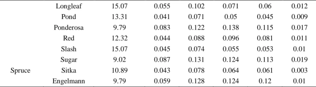
Table 3 Longitudinal Young’s modulus of wood species in Fig. 4. Other elastic moduli may be calculated using the coefficients representing their value with respect to the longitudinal Young’s modulus (Forest Products Laboratory 1999)
Species EL (GPa) ET/EL ER/EL GLR/EL GLT/EL GRT/EL
Pine Loblolly 13.53 0.078 0.113 0.082 0.081 0.013 Lodgepole 10.12 0.068 0.102 0.049 0.046 0.005
29 Longleaf 15.07 0.055 0.102 0.071 0.06 0.012 Pond 13.31 0.041 0.071 0.05 0.045 0.009 Ponderosa 9.79 0.083 0.122 0.138 0.115 0.017 Red 12.32 0.044 0.088 0.096 0.081 0.011 Slash 15.07 0.045 0.074 0.055 0.053 0.01 Sugar 9.02 0.087 0.131 0.124 0.113 0.019 Spruce Sitka 10.89 0.043 0.078 0.064 0.061 0.003 Engelmann 9.79 0.059 0.128 0.124 0.12 0.01
Table 4 Summary of input parameters used in the multi-scale framework. The panel composition are provided as given in (Chen et al. 2010)
No. Variable Symbol Value
1 Specific gravity of wood strand (Aspen) 0.39
2 Moisture content 0.07
3 Fines content by weight 0.1 4 Resin content by weight 0.03 5 Slack Wax content by weight 0.012 6 Max void content in the core 0
7 Wood composite density at the core ( ) varies
8 Resin density ( ) 1400
9 Wax density ( ) 780
10 Strand length ( ) 600 11 Strand thickness ( ) 5
12 Strand width ( ) 13
13 Wood composite density ( ) varies 14 Cell wall density at = 0% ( ) 1500
15 Resin Modulus (MPa) 7600
16 Resin Poisson’s ratio 0.3 17 Wood strand orientations: mean value (°) Mean 0 18 Wood strand orientations: STDV (°) STDV 30 19 Young's modulus of the cell wall (MPa) 35000 20 Strand modulus coefficient 1