Applicability of High Strength Concrete for Buildings in
Active Seismic Regions
by
Nicholas S. Murray
B.S., Civil and Environmental Engineering (2000) Marquette University
Submitted to the Department of Civil and Environmental Engineering in Partial Fulfillment of the Requirements for the Degree of
MASTER OF ENGINEERING in Civil and Environmental Engineering
at the
MASSACHUSETTS INSTITUTE OF TECHNOLOGY June 2001
0 2001 Nicholas S. Murray. All rights reserved.
The author hereby grants to MIT permission to reproduce and to distribute publicly paper and electric copies
of this thesis document in whole or in part.
Signature of Author ... Certified by ... Accepted by ... MASSACHUSETTS INSTITUTE OF TECHNOLOGY
JUN 0
4
2001
LIBRARIESDepartment of Civil and Environmental Engia<eing May 11, 2001
Jerome J. Connor Professor of Ci il and Environmental Engineering Thesis Advisor
.-.um ...
Oral Buyukozturk airman, Departmental Committee on Graduate Studies
Applicability of High Strength Concrete for Buildings in
Active Seismic Regions by
Nicholas S. Murray
Submitted to the Department of Civil and Environmental Engineering on May 11, 2001 in Partial Fulfillment of the Requirements for the Degree of Master of Engineering
in Civil and Environmental Engineering
ABSTRACT
The emergence of high strength material construction in highly active seismic regions is magnifying the importance of high performance structural design. High strength concrete is becoming popular because it offers the potential for cost savings in construction due to reduced member dimensions and the capability to accommodate rapid construction schedules, and because it enhances the service life of a structure. High strength concrete is commonly used in minimizing the column sizes in the lower floors of high-rise
buildings. In spite of the advantages offered by high strength concrete, lack of design provisions in building codes hinders the widespread use of the material, especially in zones of seismic activity. Another significant concern for the design of buildings in highly active seismic regions is the brittle nature of plain high strength concrete under compression. This suggests that the inelastic deformability of high strength concrete members may not be sufficient for use in active seismic regions.
It will be shown that the lack of deformability of high strength concrete itself does not result in a less ductile reinforced concrete member than that of a normal strength
reinforced concrete section. Additionally, high strength concrete offers the advantage of lower member weights, which reduces inertia forces under seismic excitation. Evidence of these claims will be offered along with advancements in structural motion control technology. Lastly, a current trend in structural engineering, performance-based design,
will be investigated to find ways to promote the use of high strength concrete in earthquake-resistant structures.
THESIS SUPERVISOR: Jerome J. Connor
ACKNOWLEDGEMENTS
I would like to express my gratitude to all those who have provided me guidance and
support. In particular, I would like to thank:
My parents for encouraging my studies through love, respect and a genuine interest in my
academic endeavors,
Professor Connor for his vision of integrating cutting edge topics in structural engineering with practical industry design principles in a graduate-level university setting,
and Lisa Grebner for never being too busy to arrange site visits, conduct group meetings at her office, offer advice on bridge projects, presentations and this thesis, and lend a helping hand in every way.
Massachusetts Institu,'e of Technology
3
TABLE OF CONTENTS T able of C ontents ... 4 L ist of F igures ... 5 L ist of T ables ... 6 1. Introduction ... 7 2. Background Information...10 3. Mechanical Properties ... 14 3.1 Strength ... 14 3.1.1 Compressive Strength ... 16 3.1.2 Tensile Strength ... 16 3.2 Modulus of Elasticity ... 17 3.3 Fracture Energy ... 19 3.4 Long-Term Deflection ... 20 3.5 Poisson's Ratio...21
4. Seismic Response Parameters...22
4.1 Ductility and Confinement ... 24
4.1.1 Column Deformability ... 24
4.1.2 Beam Deformability...34
4.2 Flexure ... 35
4.2.1 Column Flexural Strength ... 35
4.2.2 Beam Flexural Strength ... 38
4.3 Beam-Column Joint Deformability ... 40
5. Design Strategy ... 42
6. D am ping ... 48
7. Performance-Based Design...52
8. C onclusion ... 56
B ibliography ... 58
LIST OF FIGURES
3.1 Factors influencing the strength of plain concrete [14] ... 14
3.2 Comparison of ACI 318 and ACI 363 modulus of elasticity equations [2] ... 19
4.1 Failure of a high strength concrete cylinder under compression [14] ... 22
4.2 Axial stress-strain curves for normal weight concretes of different strengths [14]... 23
4.3 Effect of axial compression on column deformability [14]...26
4.4 Effect of volumetric ratio of confinement steel on column deformability [36] .... 27
4.5 Effect of reinforcement arrangement on column deformability [13] ... 29
4.6 Effect of transverse steel strength on column deformability [14] ... 30
4.7 Comparison of displacement ductility ratios of columns with different concrete strengths but constant p,f, /f' ratios [14] ... 30
4.8 Hysteretic curve for column with 20% column concentric capacity [3]...33
4.9 Hysteretic curve for column with 30% column concentric capacity [3]...33
4.10 Flexural ductility on high strength concrete beam members under m onotonic loading [13] ... 36
4.11 Proposed modification of the ACI 318-99 rectangular stress block [3]...37
5.1 Damage due to soft story columns of the Olive View Hospital from the 1971 San Fernando earthquake [26] ... 43
5.2 Shear failure of column due to "captive column" design [24]...44
6.1 Active control scheme employing an actuator and active tendons [16] ... 51
7.1 Performance concept of representative static pushover curve [17]...54
7.2 Performance matrix in FEMA-303 and IBC 2000 [17]...55
Massachusetts Institute of Technology
5
LIST OF TABLES
3.1 Proposed equations for normal and high strength concrete
m odulus of rupture [11] ... 17 3.2 Proposed equations for normal and high strength concrete
m odulus of elasticity [11] ... 18
4.1 Effect of axial compression on column deformability [14] ... 25
4.2 Effect of volumetric ratio of confinement steel on column deformability [14] .... 27
4.3 Effect of transverse steel strength on column deformability [14]...28 4.4 Comparison of flexural capacity for the ACI rectangular stress block
and the equivalent rectangular stress block [3]...38
Massachusetts Institute of Technology
6
1.
Introduction
High performance structures attain increased levels of performance through the
implementation of advanced materials, remote monitoring systems, and structural motion control schemes. Design emphasis is always placed on durability, constructability and the response of the structure to various loads. The emergence of high strength material
construction in highly active seismic regions is magnifying the importance of high
performance structural design. Before any material is employed in these areas, the design engineer needs to know how it will behave under varying loading conditions. High strength concrete has been used in high-rise construction since the early 1970's, but sufficient amounts of research on the seismic response parameters of the material are only recently becoming available. It can now be shown that the integration of high strength concrete into a properly selected structural system offers a sizeable advantage in the durability, constructability and overall response of structures in highly active seismic regions.
More high-rise structures are being constructed now than a decade or so ago. As real estate prices in urban areas continue to rise, and the trend is expected to continue, more emphasis is being placed on expansion in the vertical direction. High strength materials are becoming popular because they offer the potential for cost savings in construction due to reduced member dimensions and the capability to accommodate rapid construction
schedules, and because they enhance the service life of a structure. High strength concrete is commonly used in minimizing the column sizes in the lower floors of high-rise buildings. This design application has gained international acceptance, as shown in
Massachusetts Institute of Technology
7
the construction of the Petronas Towers in Kuala Lumpur, Malaysia. In seismic regions, typical concrete structures have a disadvantage because they are inherently heavy and hence have the potential to develop substantial inertial forces. High strength concrete members will have the distinct advantage of reducing these inertial loads due to a reduction in member sizes.
While these advantages provide incentive for using high strength concrete in the
construction industry, lack of design provisions in building codes hinders the widespread use of the material, especially in zones of seismic activity. Designers often question the applicability of building code provisions that were developed for normal strength concrete to high strength concrete. Another significant concern for the design of buildings in highly active seismic regions is the brittle nature of plain high strength concrete under compression. This material characteristic might imply that the deformability of reinforced high strength concrete columns may not be sufficient.
The focus on this paper will be on the applicability of high strength concrete into the gravity supporting systems of buildings in active seismic regions. High strength concrete has proven extremely effective in reducing column sizes for buildings in non-seismic
zones, and the implementation of this practice into regions of high seismic activity will be shown to be beneficial. Shear walls are designed to carry the bulk of the lateral
seismic forces in concrete buildings, but every beam-column frame of a structure must be designed for earthquake induced lateral deflections. Clearly, failure of the primary gravity load bearing system would have a disastrous effect on the integrity of the
Massachusetts Institute of Technology
8
8 Massachusetts Institute of Technology
structure. It will be shown that, through prudent detailing, high strength concrete columns will perform in a similar manner as normal strength concrete columns under seismic excitation, with the added benefit of reduced inertia forces.
2.
Background Information
The proportioning (mix design) of normal strength concrete is based primarily on the water to cement (w/c) ratio "law" first proposed by Abrams in 1918. It assumes that the strength of the hardened cement paste will be the limiting factor controlling the concrete strength. For high strength concretes, however, all of the components of the concrete mixture are pushed to their critical limits. Concrete may be modeled as three-phase composite materials, the three phases being: (i) the hardened cement paste, (ii) the aggregate, and (iii) the interfacial zone between the hardened cement paste and the
aggregate. The optimization of all three phases is of the utmost importance in the design of high strength concrete in seismic zones [23]. Ductility of normal strength concrete is due to the much higher strength of the aggregates than of the mortar matrix in concrete. For high strength concrete, if the aggregate is not stronger than the cement paste, cracks may penetrate the aggregate. This leads to a brittle system failure mode, similar to that of uniform materials [25]. In regions of high seismicity, building members need to be sufficiently ductile, so strength of the coarse aggregate is an important quality.
Conventional concrete has a compressive strength less than 6000psi. High strength concrete, in general, is characterized by compressive strengths in the range of 6000 to 14,000psi. Concrete capable of strengths beyond 14,000psi, up to 30,000psi and even larger, are classified as ultra high strength concrete [32]. In a State-of-the-Art Report on High Strength Concrete by the International Federation for Structural Concrete, high strength concrete is defined as a concrete having a minimum 28-day compressive strength of 8700psi. Clearly then, the definition of high strength concrete is relative; it depends
Massachuseu's Ins0,'ue of Technology
10
on both the region of the country it is produced and the period of time in question. Concrete that is considered high strength in Hawaii would be judged as normal strength concrete, at best, in Chicago due to the rate of dissemination of these material
advancements [32]. Also, even though the specified strength of concrete has been traditionally based on 28-day results, later time periods can be used. In high-rise structures requiring high strength concrete, the process of construction is such that the structural elements in the lower floors are not fully loaded for periods of a year or more. For this reason, compressive strengths based on 56- or 90-day test results are commonly specified in order to achieve significant economy in materials cost [20].
In order for a structure to behave properly under seismic conditions, more than strength considerations must be investigated. The key to high performance of a reinforced concrete structure lies in the development of a highly durable concrete matrix. Another classification, "high performance concrete," has been assigned to concrete that satisfies many of the following requirements:
(i) Very low porosity through a tight and refined pore structure of the cement paste
(ii) Very low permeability of the concrete (iii) High resistance to chemical attack (iv) Low heat of hydration
(v) High early strength and continued strength development (vi) Low water-binder ratio
(vii) High workability and control of slump loss
Massachuse's Institute of Technology
11
(viii) Low bleeding and plastic shrinkage.
Obtaining these properties requires fine-tuning of the three phases of the high strength concrete [33]. For implementation in seismic zones, high strength concrete needs added versatility, which the "high performance" aspect brings. Similar to the qualities of a high performance structure, high performance concrete is that "which is designed to give optimized performance characteristics for a given set of load, usage, and exposure conditions consistent with the requirements of cost, service life, and durability" [33].
The added dimension that makes high strength concrete a viable construction material for buildings in active seismic regions is the reinforcing steel. Without steel reinforcement, high strength concrete would be too brittle a substance for use in beam-column frames. Proper interaction between the concrete and reinforcement, throughout the design life of a structure, requires that the concrete be durable enough to protect the embedded steel. The qualities demanded of a high performance concrete will promote a more durable structure by preventing material degradation. A high level of integrity of the concrete matrix in unison with the steel reinforcement will offer a sufficiently ductile material for use in buildings in seismic-prone areas. The last two steps that need appropriate attention are proper structural design and high-quality construction.
In what follows, evidence will be put forth to examine the applicability of high strength concrete for buildings in active seismic regions. The experiments performed have all been conducted on high strength concrete cast in a controlled environment. The
usefulness of these findings will rely on the performance of the high strength concrete in
Massachusetts Institute of Technology
12
the field over the design life. Due to the past reluctance of structural engineers to use high strength concrete in seismic zones, case studies on the subject are not yet available. Lessons gained from case studies of normal strength concrete structures will be used for insight into high strength concrete design in seismic areas. Also, state-of-the-art
technology will be offered as a tool to use in the seismic design of high strength concrete frames. Lastly, a current trend in structural engineering will be investigated to find ways to promote the use of high strength concrete in earthquake-resistant structures.
3.
Mechanical Properties
3.1 Strength
The strength of concrete is perhaps the most important overall measure of quality, although, as stated above, many other characteristics are extremely important. Concrete compressive strength is widely used in specifying, controlling, and evaluating concrete quality. The quantified strength of concrete depends on a number of factors including the properties and proportions of the constituent materials, degree of hydration, and material geometry (see Figure 3.1). Two of the most dominant constituent materials, coarse aggregate and cement paste, are considered to control maximum concrete strength.
The important parameters of the coarse aggregate are its shape, texture, and maximum size. Tests have shown that crushed-stone aggregates produce higher compressive strength in concrete than gravel aggregates, using the same size aggregate and cement content, because of the superior aggregate-to-paste bond when using rough, angular,
CONCRETE STRENGTH
SPECIMEN PARAMETERS Strength of the LOADING PARAMETERS
Dimensions component phases Stress type
Geometry ,, , , Rate of stress application Moisture state
MATRIX POROSITY Aggregate TRANSITION ZONE POROSITY
Water/cement ratio porosity Water/cement ratio
Mineral admixtures Mineral admixtures Degree of hydration Bleeding characteristics
curing time, temp., humidity aggregate grading, max. size,
Air content and geometry
entrapped air Degree of consolidation entrained air Degree of hydration
curing time, temp., humidity Chemical interaction between aggregate and cement paste
Figure 3.1: Factors influencing the strength of plain concrete [2]
Massachusetts Institute of Technology
14
crushed material. Specifically, crushed aggregate from fine-grained diabase and limestone gave the highest resulting concrete strengths, while smooth river gravel and crushed granite aggregates formed weaker concretes [2]. The use of larger maximum size of aggregate affects the concrete strength in negative ways since they have less specific surface area for the cement paste to bond with. This reduced area lowers the bond strength between the aggregates and the paste, thus reducing the compressive strength of concrete.
Supplementary cementitious materials have been effective additions in improving the strength of the cement paste. Recognizing that the microstructure of concrete can be tailored to produce beneficial effects makes the dramatic improvement in strength possible. Concrete weakness and permeability is primarily a function of its porosity. Decreasing the porosity by using superplasticizers and submicron pozzolanic filler particles and fine grain sand has made the production of high strength and ultra high
strength concretes possible [2].
The most common filler particles used in high strength concrete are pozzolans,
specifically silica fume and fly ash. Fly ash is the most widely used mineral admixture in concrete. It is a finely divided residue that results from the combustion of pulverized coal in electric power plants, and is primarily silicate glass containing silica, alumina, iron and calcium. Most of the fly ash particles are solid spheres and some are hollow cenospheres, with sizes that vary from less than 1 p m to more than 100 p m, with a typical particle
size under 20 p m. Silica fume, a waste by-product of the production of silicon and
Massachusetts Institute of Technology
15
silicon alloys, is essentially silicon dioxide in noncrystalline form. It has a spherical shape and is extremely fine, having particles sizes less than 1 p m and an average size of 0.1 p m, which is about 100 times smaller than average cement particles. For every mix design there will be an optimum cement-plus-pozzolan content at which the addition of pozzolanic material does not increase the strength, and the mixture becomes too sticky to
handle properly [20].
3.1.1 Compressive Strength
Neither ACI 318-99 nor any of the three model codes in the United States imposes an upper limit on the compressive strength of normal weight concrete that can be used in construction, even in regions of high seismicity. The City of Los Angeles is the only city with an informal regulation on the maximum specified concrete compressive strength (f'_ = 6000 psi) used in specially detailed moment frames [15].
3.1.2 Tensile Strength
The tensile strength of concrete is important because it governs the cracking behavior and influences seismic response parameters such as stiffness, damping action, bond to
embedment steel and durability of concrete. The tensile strength is often obtained of concrete through two indirect testing procedures, the splitting tension test (ASTM C496) and the third-point flexural loading test (ASTM C78). The ACI High Strength Concrete Committee 363 recommends the splitting tensile strength of normal weight concrete
(flu)
be taken as:fe
= /7.4 , psi for 3000 sf'
12,000 psi (3.1)Ahmad and Shah [2] presented an empirical formula for concretes of low, medium and high strength:
fet = 4.34(f')psi for
f'
12,000 psi (3.2)Flexural strength, or modulus of rupture, is measured by a beam flexure test and is regarded as a more reliable measure of the tensile strength of concrete. Several researchers have generated equations of the modulus of rupture,fi, for high strength concrete to supplement the equations provided by the two ACI equations (see Table 3.1).
Of the two ACI formulas, the ACI 318 equation is recommended for high strength
concrete design due to lack of conservatism of the ACI 363 equation [11].
3.2 Modulus of Elasticity
As concrete compressive strengths increase, so increases the slope of the linear portion of the stress-strain curve. The static, secant modulus of elasticity, Ec, is defined by the ACI
Building code as the ratio of stress at 45% of the strength to the corresponding strain. Increased wind susceptibility of buildings dictate that the modulus of elasticity of construction materials be as high as possible [8]. This is because the modulus of
elasticity of a material is directly proportional to its stiffness, which is also very valuable in seismic design. High strength concrete will have a higher modulus of elasticity, and
Modulus of Rupture,f,
psi MPa
ACI 318-99 7.5 5ff 0.62
f_'
ACI 363 11.7
fe'
0.97fc'
New RC
I9.5(f'
0 4 5 1.26(f)Ahmad and 2shah 2.3(fV')0 6 7 0.44(f0')0 6 7
Setunge 2.5(f') 0 6 5 ±25%
0.44(f') 0 65
+25%
Table 3.1 - Proposed equations for normal and high strength concrete modulus of rupture [11]
Modulus of Elasticity, E, psi Mpa ACI 318-99 33w 5
f'
0.043w 5f
ACI 363 40,00 f'+106 3320f+6900 New RC 4.86 x 10⁶ kik2 (f /8700)0.33 (w/150)2 33,500kjk 2(f; / 60).33 (w/ 2400)2 Lambotte 262,00(f)1 39,500(f)
1 /3 Cook 2.SS (fF)O.31S 2.8 x w 5 .1 5 Ahmad 2.5 (f.)0325 3.38 x 10⁻⁵ "(f;)0.3 25 Tachibana 47,560 f+226,200 3950f+
1560Table 3.2 - Proposed equations for normal and high strength concrete modulus of elasticity [11]
thus higher stiffness, than normal strength concrete members of equivalent size.
Countless researchers have put forth empirical relationships for the modulus of elasticity from experimental data on high strength concrete (see table 3.2) [11]. The ACI 318 equation and the ACI Committee 363 equation are shown plotted in Figure 3.2 for a unit concrete weight, w, equal to 145 lb/ft3. The ACI 318 equation is shown to generally
overestimate the value of the modulus of elasticity for the higher strength specimens, whereas the equation provided by ACI 363 was more appropriate for the acquired data. The equation offered by Cook was derived from a best-fit curve of Figure 3.2. Since the
ACI 363 equation always predicts more conservative values for the modulus of elasticity,
it is most often recommended in practice [2].
Massachusetts Institute of Technology
18
8.0 0 o Normal wt. 0 0 * o 7.0- 0 * ,.0 6 . - .0 - 40 ' 4.0 - 3.6 0 a 0 0I_; 20 40 60 80 100 120 0 ps,
Figure 3.2: Comparison of ACI 318 and ACI 363 modulus of elasticity equations [2] The values obtained for the modulus of elasticity of concrete are greatly influenced by the modulus of the coarse aggregate used. Aggregate with a higher modulus of elasticity will contribute to a concrete with a higher modulus of elasticity. The shape of the coarse aggregate particles and their surface characteristics may also affect the value obtained. These factors are integrated into the constants, k1 and kc2, in the equation for the modulus of elasticity offered by the Japanese Building Research initiated "New RC Project" (see Table 3.2). Additionally, it is generally accepted that concrete specimens tested in wet conditions showed about 15% higher elastic modulus than the corresponding specimens tested in dry conditions due to the microcracking during dry shrinkage [32].
3.3 Fracture Energy
The behavior of a reinforced concrete structure is strongly dependent on the bond between the concrete and the reinforcing steel bars. The prediction of the linear or nonlinear response of reinforced concrete structures subjected to static or dynamic loads, regardless of the method of analysis, is based upon our knowledge about the local bond
stress vs. slip relationship governing the behavior of the concrete-steel interface. For reinforced concrete structures it is essential that the bond between the reinforcing bar and the concrete exhibit a certain "ductility" during dynamic loading. That is, the bond resistance in the member should decrease gradually instead of suddenly failing, so that dynamic energy can largely be transferred, absorbed and dissipated to the entire structural member over a relatively long time period. This bond "ductility" may be represented by the fracture energy, which is calculated as the work done by the bond stress. A larger value of fracture energy means a more "ductile" bond. Research by Yan and Mindress showed that dynamically loaded high strength concrete specimens always exhibit higher bond strength and absorbed more fracture energy (about 2.5% to 6.7%) than normal strength reinforced concrete members [39]. The shear mechanism is the main mechanism for the bond resistance of deformed bars. The force transferred by the concrete
surrounding the rebar increases with an increase of the shear strength of concrete, which is, to some extent, proportional to the compressive strength [39].
3.4 Long-Term Deflection
Shrinkage values for normal strength and high strength concrete are roughly the same. Creep per unit stress (specific creep), however, decreases significantly as concrete strength increases. This will, in turn, lead to less long-term deflection. Currently, this point is not reflected in long-term deflection multiplier (A.) in the ACI 318-99 code [1]. Section 9.5.2.5 of the code specifies that, unless values are obtained by a more
comprehensive manner, additional long-term deflection resulting from creep and
shrinkage of flexural members shall be determined by multiplying the immediate deflection, caused by the sustained loads considered, by the factor:
A - (3.3)
1+ 5 0p'
where the compression reinforcement ratio p' shall be the value at midspan for simple and continuous spans, and at the support for cantilever beams. The time-dependent factor, , for sustained loads may be taken equal to:
2.0 for a loading duration of 5 years or more 1.4 for a loading duration of 12 months 1.2 for a loading duration of 6 months
1.0 for a loading duration of 3 months
It is believed that the multiplier is not conservative enough for normal strength concrete, and relatively accurate for high strength concrete members [15]. This point becomes important for long-span high strength concrete beams, where deflection controls the design. If the high strength concrete beam had a codified deflection advantage over normal strength concrete, greater reductions in member size could occur.
3.5 Poisson's Ratio
Experimental data of v for high strength concrete is very limited. Based on the available information, the Poisson's ratio of high strength concrete appears comparable to values for normal strength concrete (v = 0.20) [2]. Poisson's ratio is an important mechanical property of concrete for seismic applications because it affects the concrete confinement,
and thus the concrete displacement ductility of a member.
4.
Seismic Response Parameters
In areas of medium to high seismic exposure, it is not possible to design structures economically on a strength basis. Therefore, the simple fact that new construction
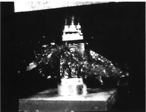
materials offer higher strength to the designer than conventional ones should not be cause for celebration. It is their deformational characteristics that should be studied from an earthquake engineering viewpoint. In the case of high strength concrete, as the compressive strength increases, the concrete itself becomes less deformable, or more brittle. The shape of the stress-strain curve for high strength unconfined concrete in uniaxial compression shows a near linear region up tof', at a longitudinal strain of about
0.003, and then a sharp fall off of load carrying capacity. Figure 4.1 shows the explosive
failure of a high strength concrete cylinder, indicating the extent of its brittle nature. Figure 4.2 shows the axial stress-strain curves and axial-lateral strain curves in compression of normal weight concrete having different strengths. Normal strength
Figure 4.1: Failure of a high strength concrete cylinder under compression [14]
n, (ksi) Unit weight =150.75 lbs/ft3 7 -1 - 7
Strain rate = 10 pu/sec
f (k s i) 6 - 6 1 5.3 5 5 2 7.0 9 3 7.7 4 8 4 8.2 3 5 9.1 -7 2 6 10.1 -6 7 12.0 1 1 5 -4 -3
+-ea 2- Axial strain,
':2 = 3 (in/in) F' (in/in)
I I I I
0.020 0.016 0.012 0.008 0.004 0.002 0.004 0.006 0.008
Figure 4.2: Axial stress-strain curves for normal weight concretes of different strengths [14] concrete can only develop a modest level of stress, but it can sustain this stress over an appreciably larger range of strains. Higher strength concretes attain a much higher level of stress, and a higher axial strain at ultimate stress, but cannot sustain the stress over any significant range of strains. The load-carrying capacity drops precipitously once the ultimate stress is attained [14].
Interestingly, it will be shown that the lack of deformability of the high strength concrete itself does not necessarily result in a less ductile reinforced concrete member than that of a normal strength reinforced concrete section. For the purposes of seismic engineering applications, focus needs to be placed on the inelastic deformability of high strength concrete structural members under reversed cyclic loading. The design and detailing of high strength concrete members will parallel that of normal strength concrete. Although the difference in compressive strengths does not make the two concretes completely different materials, their behavior is unique enough to justify separate guidelines and
procedures for engineers to follow. Engineers are skeptical, with good reason, of the applicability of codes that were formulated for normal strength concrete to the design of high strength concrete members.
4.1 Ductility and Confinement
In the design of ductile frames, the earthquake-induced energy is dissipated by the inelastic response of potential plastic hinges in beams and columns. Therefore, the ductility assurance of the plastic hinge regions is of primary importance in ductile frames. Plastic hinges, as mentioned earlier, are designed to occur in the beams. However, if the column experiences inelastic stress conditions, it is vitally important that it behaves in a ductile manner [36].
4.1.1 Column Deformability
Deformability of high strength concrete columns plays a large role in providing overall strength and stability to earthquake resistant structures. For columns, inelastic
deformability is the ability of a reinforced concrete member to deform laterally beyond the stage of significant yielding of the tension reinforcement, while sustaining
substantially all the axial load strength [15]. High deformability requirements in the first-story columns of multifirst-story buildings can only occur through confinement of the core concrete. As mentioned earlier, the only limit on the strength of concrete that can be used in construction in the United States is in the City of Los Angeles; where there is an informal limit of 6000psi on the specified strength of concrete used in special moment frames. This limitation stems from concerns of engineers over the inelastic deformability of columns subjected to high levels of axial load and high-amplitude reversed cyclic
Massachusetts Institute of Technology
24
lateral displacement [15]. Research has been conducted on the behavior of axially loaded columns (P > A / 10 ) subjected to both monotonic lateral loads and cyclic lateral loadings. For studies cited in this section, concrete strengths in the range of 4800 to
16,800psi have been considered.
The axial compression induced upon columns reduces its deformability, regardless of concrete strength. In a study by Watanabe et al., high strength concrete columns tested under constant axial compression and incrementally increasing lateral load reversals experienced a reduced displacement ductility ratio, u, with increased compression (see Table 4.1 and Figure 4.3) [14]. The displacement ductility ratio is defined as the ratio of maximum displacement recorded prior to exceeding 20% strength decay under cyclic
loading, over the yield displacement. Cyclic loading consists of at least two cycles at each of the incrementally increasing deformation levels, where each increment is less than twice the yield displacement. A ductility of 4 is used as a benchmark of a relatively
conservative minimum requirement for members subjected to gravity plus wind or moderate seismic loads [13].
Column ' p% Jy, v/Vf P/(AJ'
no. (psi) (%) (ksi) s/h s1/h (psi) (%)
45 12,260 2,57 121 0.14 0.25 8.4 28 6.3 50 12,260 2.57 121 0.14 0.25 8.4 51 5.0 44 9670 2.00 121 0.18 0.25 9.0 31 6.7 48 9670 2.25 121 0.16 0.25 9.6 57 3.5 40 12,430 4.37 48 0.17 0.26 8.9 63 2.0 42 1680() 4.37 48 0.17 0.26 8.9 42 3.3 41 12.430 4.37 115 0.17 0.26 9.0 63 7.3 43 16,8) 4.37 115 0.17 0.26 8.9 42 8.0 51 13,2(X) 1.41 193 0.16 0.38 9.4 35 5.0 52 13,200 1.41 193 0.16 0.38 10.0 52 2.6
1 in. 25.4 mm; 10) psi = 6.895 MPa
Table 4.1 - Effect of axial compression on column deformability [14]
70 -60 40 48 64 1 50 5 050 -40- 643 30 -51 o44 45 20-10- 40-52: column numbers 42. 0 2 4 6 8 10
Displacement ductility ratio
Figure 4.3: Effect of axial compression on column deformability [14]
Confinement of the column concrete is an important parameter of overall ductility. An increase in the volumetric ratio of confinement steel directly translates into a
corresponding increase in confinement pressure, and resulting improvements in concrete deformability. In a study by Saatciouglu [30], 7280psi concrete with 2.2% confinement steel shows a strain ductility ratio of approximately 3; while the same concrete confined with 7.5% reinforcement shows an increased ductility ratio of about 12 (see Table 4.2). The strain ductility ratio is another measure of concrete deformability, and it is obtained from column tests under concentric compression. The strain ductility ratio ('85 /' ) is defined as the ratio of concrete strain at 85% of the peak stress on the descending branch, to the strain corresponding to the peak stress. Figure 4.4 shows an instance where a column with 4.26% double spiral transverse reinforcement displays greater ductility than a column reinforced with single spiral reinforcement [36].
Massachusetts InsUi~u,~e of Technology
26
Column no. A (psi) p, ( ) f1,(ksi) s/h I 1HX)() 2.1 198 0.34 1( I (X)00 4.2 198 0.34 11 7280 2.2 55 0.05 14 7281 7.5 60 0.06 12 7280 2.2 55 0.05 15 7281 7.5 60 0.06 13 7280 2.2 55 0.05 16 7281 7.5 60 0.06 _ 8447 3.4 6) 0.06 16 7281 7.5 64) 0.06
1 in. = 5. 4 nmm I() psi 6.895 MPa
s I/h F / F N/A 1.8 N/A 7.6 N/A 3.4 N/A 12.6 N/A 3.2 N/A 15.2 N/A 3.2 N/A 11.9 N/A 2.7 N/A 11.9
Table 4.2 - Effect of volumetric ratio of confinement steel on column deformability [14]
Transverse steel reinforcement, in the form of ties or spirals, serves four different functions in a column, including: (i) holding the longitudinal steel in place during concrete pouring; (ii) serving as shear reinforcement; (iii) preventing the buckling of longitudinal compression reinforcement; and (iv) serving to confine the concrete. A significant enhancement in bond performance of longitudinal reinforcement is produced by confinement. A proper amount of confinement steel places the concrete around the longitudinal reinforcement in more of a three-dimensional state of compression, thus increasing the capacity [22]. Another important design detail is that confinement in columns should continue through the joint region. Also, to be effective, transverse
100
Confined columns --- Plain concrete column
80 P 84.5MPa p =4.26% 60 f 87.5MPa =2.13% 40. P=59.7MPa o =2.13% f =43.6MPa p =2.13% 20 Yielding of hoops k k maximum f = 1360MPa 0 0.5 1 1.5 2 2.5 Strain (%)
Figure 4.4: Effect of volumetric ratio of confinement steel on column deformability [36]
I
reinforcement must be coupled with well-distributed longitudinal reinforcement [24]. Figure 4.5 shows the benefit of an increase in confinement due to added transverse reinforcement and longitudinal steel. For columns under low axial load levels,
prevention of buckling of the longitudinal steel, rather than confinement of the concrete, becomes the primary function of the transverse reinforcement [13].
Research by Muguruma et al. indicates that very high ductilities can be achieved in high strength concrete when it is confined by high strength steel. Columns with 12,500 to
16,800psi concretes confined with 4.4% volumetric ratio of steel show approximately
250% increase in displacement ductility ratios when the steel yield strength is increased by 140% (from 48 to 1 5ksi) (see Table 4.3 and Figure 4.6) [14].
This dramatic increase can be attributed to the findings that the improvement associated with the use of high strength steel as confinement reinforcement is approximately the same as that obtained by increasing the volumetric ratio of normal strength confinement steel (p,) by the ratio of
f,
(hss) /f, (nss). It is also observed that higher confinementpressure (i.e. higher psfy,) is required for higher strengths of concrete to maintain
Column . '(psi) p, ("%) s/h si I/h V'/\VIi (psi) P/(A1 ') f., (ksi) s
no. (%) 40 12430 4.37 0.17 0.26 8.9 63 48 2.0 41 12430 4.37 0.17 0.26 9.0 63 115 7.3 42 16800 4.37 0.17 0.26 8.9 42 48 3.3 43 16800 4.37 0.17 0.26 8.9 42 115 8.0 47 9670 2.60 0.20 0.25 9.9 57 46 2.5 48 9670 2.25 0.16 0.25 9.6 57 121 3.5 49 9670 2.08 0.18 0.25 9.5 57 198 5.0 55 145(W 1.55 0.24 0.25 9.5 35 50 1.7 53 14500 1.28 0.24 0.25 8.7 35 112 2.0 56 145WX 1.28 0.24 0.25 8.7 35 163 3.3
1 in. 25.4 mm: 1000 psi = 6.895 MPa
Table 4.3 - Effect of transverse steel strength on column deformability [14]
140- CS-3 120- fe= 124 MPS 100-0. 80-* 60- '% 40-20- Cs-I 0 0 0.5 1 1.5 2 2.5 3
Strain
(%)
(a) 140- CS - 14 120- r = 92 MPa 100-cc 0. 60- CS -13 ' Ca40- 2 0-0 0.5 1 1.5 2 2.5 3Strain
(%)
(b)Figure 4.5: Effect of reinforcement arrangement on column deformability [13]
250-200- 049 A56 150-53 41 A 48 0 043 100 -50- A 0 55 40 '47 42 40-56: Column numbers 0 2 4 6 8 10
Displacement ductility ratio
Figure 4.6: Effect of transverse steel strength on column deformability [14] equivalent levels of deformability. To illustrate this fact, data from two independent research studies, one on normal strength concrete and one on high strength concrete, was compared based on the non-dimensional ratio pf,,
/f,'.
Figure 4.7 shows column pairs with constant p,f,,/ f'
ratios, but possessing distinctly different concrete strength, demonstrate similar displacement ductility ratios.One of the important design issues that this fact raises is the manner that the higher value of pf,, is obtained. Higher values of this product can be achieved either by the use of higher volumetric ratio and/or higher strength of confinement steel [14]. The ACI 318-99
8T6 -C, a) E 2 -0
Figure 4.7: Comparison of displacement ductility ratios of columns with different concrete strengths but constant psf,, If' ratios [14]
currently limits the strength of reinforcing steel that can be specified in earthquake resistant columns to 60,000psi (a yield stress of 80,000psi is allowable for reinforcement of columns in non-seismic zones) [1]. The reason for this limit, from Notes on ACI318-99 [10], is the belief that an increase in yield strength of the tensile reinforcement tends to decrease the ultimate curvature and hence the section ductility of a member subjected to flexure. This code provision constrains the structural engineer to increase the volumetric ratio of normal strength transverse steel in high strength concrete, which raises concerns of construction problems due to steel congestion. Studies cited in this report indicate that an increase in the allowable steel strength would be appropriate.
A study by Saatcioglu recommends allowing steel grades up to 90,000psi for concrete
structures in seismic regions. An increase in yield strength beyond 90,000psi, according to Saatcioglu, should be considered with care. Results from concrete columns reinforced with 145,000psi steel, possessing a pf, /f' ratio approximately equal to that required by ACI 318, showed inadequate ductility. Concrete columns in the same study using
145,000psi steel and a 12-bar longitudinal arrangement, instead of an 8-bar design, had sufficient ductility [29]. In the tests summarized by Ghosh et al., transverse steel reinforcement of 198,000psi was used in high strength concrete columns that achieved adequate ductility for use in seismic regions (i.e. p > 4).
Research data indicates that high strength columns designed on the basis of seismic provisions of ACI 318 exhibit satisfactory levels of ductility when subjected to moderate levels of axial compression. Columns loaded beyond a certain percentage of their
Massachusetts Institute of Technology
31
capacity have displayed inadequate inelastic response to a combination of lateral and concentric loads. Azizinamini et al. offer representative hysteretic curves for columns tested under 20% and 30% of column concentric capacity and reversed lateral load cycles
(see Figures 4.8 and 4.9). The results show that columns under 20% of concentric axial load capacity were able to develop displacement ductility levels near 6 and lateral drifts of 4%, while those tested with 30% developed displacement ductilities close to 5 with lateral drifts reaching 3%. This shows, again, that the deformability of high strength concrete columns decreases as the level of axial compression increases, which is also true for normal strength concrete columns [3]. Razvi et al. found that high axial compression in excess of 40% column concentric capacity may result in lateral drift capacities less than 2%, indicating a brittle response [3].
This reduction of lateral drift capacities for columns under heavy concentric loads is attributed to the reduction of moment capacity due to P-5 effects. Saatcioglu warns that for high strength concrete columns the P- 5 effect becomes more pronounced since they are usually subjected to very high axial loads per cross-sectional area [29]. A first story column of a multistory building may develop significant lateral drift during a seismic event. The vertical load carried by the column imposes P-S moments onto the columns in addition to the bending moments generated by lateral seismic forces. As P- S
moments increase with inelastic deflections, a large portion of column flexural resistance is consumed by these moments, leaving little resistance to lateral forces. The proper manner to design high strength concrete columns in order to avoid these deleterious effects, according to Saatcioglu, is to place an upper limit on the design axial
Massachusetts Institute of Technology
32
D60-15-3C-1 5/8-0.2P 200- Displacement Ductility 1 2 2.6 3.5 4 5 6 7 150-
...
....
I... ...
100 - 50- -50--100-. 6 5 4 35 26 2 D Ypl~ccmnent DucUity -2 -1 5 -I -05 0 0.5 15 2 Deflection (inches)Figure 4.8: Hysteretic curve for column with 20% column concentric capacity [3]
D60-15-3C-1 5/8-0.3P 200 o-o- ISO-01
0
-so-N 0 5 0... 2 16 aIM nt Ductiy Deflection (inches)Figure 4.9: Hysteretic curve for column with 30% column concentric capacity [3]
compression (P / Af') of the column [29]. The studies offered in this section would point to a limiting concentric axial load between 20 and 30% of capacity, which is less than the maximum allowable axial load according to ACI 318-99, which is equal to
0.56PO (P,o is the nominal axial capacity of the column at zero load eccentricity) [6].
Another caution when designing the axial load bearing capacity is that strength of high strength concrete columns may be affected by premature spalling of concrete cover due to the instability of the concrete shell forming the cover [3]. Columns with compressive strengths of 11,000psi and higher were observed to develop early spalling of concrete cover prior to developing axial strains associated with concrete crushing. To account for this observation, a conservative estimate of column concentric axial load capacity can be obtained if only the core area is used in the calculation:
PO = 0.85fc'(Acre - As)+ AsfY (4.1)
The same paper also pointed out that in-place strength of high strength concrete in columns is closer to concrete cylinder strength than that in normal strength concrete columns. Tests indicate that the factor of 0.85 in Equation 4.1, which accounts for observed differences in the strength of concrete in columns compared with strengths of cylindrical specimens from the same mix, can be taken as 0.90 [3].
4.1.2 Beam Deformability
As specified by ACI code, concrete columns are considered flexural beam members if the factored axial compressive force on the member, P, , is Af'l10 . Tests have been conducted by Kumara on high strength concrete beam elements that are reinforced as columns, with the longitudinal reinforcement equally divided into the tension and
compression areas, under purely lateral monotonic and cyclic loading. It should be noted that tests conducted on the deformability of high strength concrete beams are not as
numerous as for column members (P. > Agf'/10 ). The findings of the research by Kumara is that for the same amounts (and same strengths) of longitudinal and confinement reinforcement, the ductility index rises sharply as concrete strength increases from 4000 to 12,000psi, but then decreases somewhat as
f'
increases to 15,000psi (see Figure 4.10) [13]. It can also be seen from Figure 4.10 that for the same concrete strength, the ductility ratio decreased with increasing amounts of longitudinal steel. These results are suggested to arise from the fluctuation in the neutral axis depth, and its effect on the post-yield deformation of reinforced concretes load-deflection response. As concrete strength is increased, the depth, c, shifts towards the compression face and ductility is enhanced; and as longitudinal steel reinforcement is increased the neutral axis shifts toward the tension face and ductility is reduced [14]. Mostimportantly, every specimen tested by Kumara, both under monotonic and cyclic
loadings, achieved a ductility of at least 4, which leads to the conclusion that they would perform well under seismic excitation.
4.2 Flexure
4.2.1 Column Flexural Strength
The flexural strength of columns in beam-column frames is important to quantify because of the design requirement of to have 20% more moment capacity in the columns than in the girders framing into that joint. This provision stems from the strong column-weak
Massachusetts Instiu,~e of Technology
35
20
J
14 f'c, psi (MPa)
* 4250 (29.3)
12o S* 12200 (84.1)15000 (103.4)
+ Limit of machine stroke reached
10
S4r
8
0 0.2 0.4 0.6 0.8 1.0
P Pb
Figure 4. 10: Flexural ductility of high strength concrete beam members under monotonic loading [13]
beam design philosophy. In practice, columns are subjected to at least some bending even if the bending is caused by an accidental eccentricity. Therefore, current building codes also require a minimum moment capacity under the design axial load.
The strength of a reinforced concrete section under combined flexure and axial load can be evaluated by means of plane section analysis. The rectangular stress block defined in the ACI 318-99 was intended for normal strength concrete, and may not be applicable to high strength concrete members. For typical normal strength concrete columns,
experimental flexural strengths are usually greater than 1.2 times the ACI code
provisions. However, research by Azizinamini et al. has shown that the current ACI 318 Building Code requirements provide an overestimation of flexural strength of high strength concrete columns. Furthermore, the overestimation becomes more pronounced
0.003 inlin 0.85 f, 0.63 f
0.67C
Column Strain Triangular Equivalcnt
Cross Scction Distribution Sircss Rcctangular
Distribution Compression Block
Figure 4.11: Proposed modification of the ACI 318-99 rectangular stress block [3]
as the level of axial compression increases. An explanation for this discrepancy is that the stress-strain curve for unreinforced high strength concrete under compression is characterized by a steeper ascending portion that is primarily linear, as opposed to the more curved normal strength concrete stress-strain curve [3]. A modification of the rectangular stress block has been suggested to take the form of a triangular stress block for concrete with compressive strength exceeding 10,000psi (see Figure 4.11). The proposed triangular stress block is assumed to have maximum stress at the extreme fiber and zero stress at the neutral axis.
Traditionally, the peak concrete stress is assumed to be 0.85f,' at a maximum
compressive fiber strain of 0.003. It can be shown that, by keeping the area under the stress curve constant, a modified rectangular stress block, derived from the triangular stress block, will have a stress intensity, a,, of 0.63 and a depth of compression block,
i, of 0.67. From this observation a general formula for the stress intensity coefficient for concretes with compressive strengths greater than 10,000psi is given as:
al = 0.85 - 0.05(fc' - 10,000)/1000 0.60 (4.2)
and
pl
is always taken as 0.65 [3]. The ACI 318-99 code assumes that the intensity of the concrete stress block remains constant at 0.85 regardless of concrete strength, and that the relative depth of the stress block decreases between compressive strengths of 4000 and 8000psi from 0.85 to 0.65.Research by Azizinamini et al. that compares the recorded flexural strengths for columns
with concrete strengths greater than 14,500psi to the analytical predictions obtained by using Equation 4.2 is given in Table 4.4. The results show that with the revised flexural strength equations a more conservative prediction of column strength is obtained.
4.2.2 Beam Flexural Strength
The advantages of employing high strength concrete in beam construction are not considered as great as for columns. Ideally, high strength concrete would allow for
MMAX MMAX
experimental, MAC, MAE
-Test in.-kips in.-kips in.-kips MAcI ME
D60-7-4-2%-0.2P 2195 1762 - 1.25 D60-7-3C-1/e-0.2P 2104 1714 - 1.23 -D60-15-4-2%-0.2P 2402 2588 2300 0.93 1.04 D60-15-3C-15/-0.2P 2612 2577 2291 1.01 1.14 D120-15-3C-2%-0.2P 3362 2600 2312 0.91 1.02 D120-15-3C-1%-0.2P 2550 2602 2313 0.98 1.1 D60-4-3C-2%-0.2P 1533 1275 - 1.2 -D60-4-3C-2%-0.4P 1489 1375 - 1.08 -D60-15-3C-1%-0.3P 2691 3104 2395 0.87 1.12
Table 4.4 - Comparison of flexural capacity for the ACI rectangular stress block and the equivalent rectangular stress block [3]
Massachusetts Insutute of Technology
38
smaller member sizes and longer beam spans, which would allow wider column spacing. However, as the span length increases, deflection restrictions control the design of the beam instead of the flexural strength. High strength concrete does have a higher modulus of elasticity than its normal strength counterpart, but the rate of reduction in the moment of inertia by reducing the cross-section is greater than the increase of elastic modulus. For the same reason, high strength concrete has not been shown effective in shear wall design, as the primary function of the walls is to provide stiffness, not strength [34].
While there is compelling evidence to modify the rectangular stress block derived for normal strength concrete for application to high strength concrete columns, flexural calculations are not sensitive to the stress block when the axial compression is low. The compression zone in pure flexural members is relatively small when compared to
members under combined axial and bending loads. If the amount of tension reinforcement is held constant in a beam member, an increase in the concrete
compressive strength causes the neutral axis to shift higher in the section (towards the compression face) to maintain equilibrium between the compressive and tensile stresses
[11]. Experiments show a small increase in flexural capacity of high strength concrete
beam members due to the increase in moment arm from the upward shift of the neutral axis. In general, however, sectional flexure response is mainly dominated by the behavior of the steel rather than the concrete.
Pam et al. found that for rectangular reinforced concrete beams spanning between 20 and
50ft, increasing the concrete strength will reduce the beam depth. A beam depth
Massachusetts Insiftute of Technology
39
reduction of 13% was realized when concrete strength was increased by a factor of 6, from 3000psi to 18,000psi. This 13% reduction holds for beams throughout the span range (from 20 to 50ft). However, for long span rectangular prestressed concrete beams
in the range of 40 and 1 00ft, deflection criteria controlled the design and no beam depth reduction occurred [27]. It should be pointed out that the long-term deflection of high strength concrete has been shown to be less than that of normal strength concrete, but the current design codes do not reflect this characteristic.
4.3 Beam-Column Joint Deformability
Beam-column joints designed for seismic loading must perform in a ductile fashion and dissipate energy in a manner that does not compromise the strength of the entire
structure. During a strong-motion earthquake, beam-column connections in reinforced concrete moment-resisting frames can experience severe cyclic loading. The lateral displacement of a frame places beam-column joints under high shear stresses because of the change from positive to negative bending in the flexural members from one side of the joint to the other [26]. ACI-ASCE 351 has limited the shear stress in the joint
members to y
f'
, where y is a function of the joint type (i.e. interior-20, exterior-15 or corner- 12) [31]. The location of the joint is relevant, as evidence has shown that the more pairs of horizontal members framing into opposite sides of a joint results in enhanced joint shear strength. When high strength concrete columns are used, these joints can consist of either normal strength concrete or high strength concrete, dependingon the concrete compressive strength specified for the beams and the manner in which the
Massachusetts Institute of Technology
40
joint is cast. Again, concern has been raised to the applicability of current codes if high strength concrete comprises the joint material.
When hinges form in a beam, or in extreme cases within a column, the moments at the ends of the member, which are governed by flexural strength, determine the shear that must be carried. For members with inadequate shear capacity, the response will be dominated by the formation of diagonal cracks, rather than ductile hinges, resulting in a
substantial reduction in the energy dissipation of the member [31]. Experiments have shown that high strength concrete specimens with low shear level and high joint confinement display less stiffness degradation and loss of load-carrying capacity at displacements beyond the yield displacement. Other specimens with high joint shear stress and/or low joint confinement levels suffered greater strength loss and lower ductility [14]. Additionally, research by Ehrani et al. has concluded that properly detailed connections constructed with high strength concrete exhibit ductile hysteretic response similar to those for normal strength concrete joints. However, the maximum allowable joint stress, given by ACI-ASCE 351, did not increase at a rate of the square root of the compression strength. It has been recommended that the y term also
incorporate the concrete compressive strength, although no suggestion was offered [14].
Massachusetts Institute of Technology
41
5.
Design Strategy
Observations of the performance of reinforced concrete structures during strong earthquakes have supplied engineers and builders the lessons of proper and improper design and construction of earthquake load resisting systems. An engineer intuitively knows that the proper selection of the load carrying system is essential to optimal
performance under any loading conditions. A properly selected structural system tends to be relatively forgiving of minor oversights in analysis, proportion, detail, and
construction. Conversely, extra attention to analysis and detail is not likely to improve significantly the performance of a poorly conceived structural system [24].
0 Continuity
Continuity is an essential characteristic of any load resisting system so that the loads are offered a continuous path to the foundation. Inertial loads that develop due to
accelerations of individual members must be transferred from the individual element to the floor diaphragms, to vertical elements in the lateral load system, to the foundation, and then to the ground. A lack of adequate strength or toughness in any one element, or a failure to tie individual members together can result in distress or complete collapse of the system. Failures due to discontinuity of vertical elements of the lateral load resisting system have been among the most noted and spectacular [24]. One common instance is when shear walls that are present in upper floors are discontinued in lower floors. The debilitating result is that of a soft first story which experiences concentrated damage and compromises the integrity of the entire structure, as can be readily seen in Figure 5.1
[26].
Massachusetts Institute of Technology
42
Figure 5.1: Damage due to soft story columns of the Olive View Hospital from the 1971 San Fernando earthquake [261
Regularity
Regularity of the structure is beneficial in earthquake-prone regions. Abrupt changes in stiffness, strength, or mass in either vertical or horizontal planes of a building can result in distributions of lateral loads and deformations different from those that are anticipated for uniform structures. Mass, stiffness, and strength plan irregularities can result in significant torsional response, causing concentrations of inelastic deformations in or around the discontinuity. Commonly observed discontinuities are setbacks, changes in story height, unanticipated contribution of nonstructural components, and changes in materials. Although high strength concrete would be phased out in the higher floors, thus changing the material properties, a consistent column dimensions and column weight can be maintained throughout the entire height of the structure.
Massachusetts Institute of Technology
43
![Figure 3.1: Factors influencing the strength of plain concrete [2]](https://thumb-eu.123doks.com/thumbv2/123doknet/14026554.457818/14.918.218.690.713.1022/figure-factors-influencing-strength-plain-concrete.webp)
![Table 3.1 - Proposed equations for normal and high strength concrete modulus of rupture [11]](https://thumb-eu.123doks.com/thumbv2/123doknet/14026554.457818/17.918.120.786.819.1050/table-proposed-equations-normal-strength-concrete-modulus-rupture.webp)
![Table 3.2 - Proposed equations for normal and high strength concrete modulus of elasticity [11]](https://thumb-eu.123doks.com/thumbv2/123doknet/14026554.457818/18.918.117.786.110.406/table-proposed-equations-normal-strength-concrete-modulus-elasticity.webp)
![Figure 3.2: Comparison of ACI 318 and ACI 363 modulus of elasticity equations [2]](https://thumb-eu.123doks.com/thumbv2/123doknet/14026554.457818/19.918.267.647.167.407/figure-comparison-aci-aci-modulus-elasticity-equations.webp)
![Figure 4.2: Axial stress-strain curves for normal weight concretes of different strengths [14]](https://thumb-eu.123doks.com/thumbv2/123doknet/14026554.457818/23.918.261.654.172.458/figure-axial-stress-strain-curves-concretes-different-strengths.webp)
![Table 4.1 - Effect of axial compression on column deformability [14]](https://thumb-eu.123doks.com/thumbv2/123doknet/14026554.457818/25.918.223.715.787.1016/table-effect-axial-compression-column-deformability.webp)
![Figure 4.3: Effect of axial compression on column deformability [14]](https://thumb-eu.123doks.com/thumbv2/123doknet/14026554.457818/26.918.289.643.121.354/figure-effect-axial-compression-column-deformability.webp)
![Figure 4.4: Effect of volumetric ratio of confinement steel on column deformability [36]](https://thumb-eu.123doks.com/thumbv2/123doknet/14026554.457818/27.918.211.701.117.331/figure-effect-volumetric-ratio-confinement-steel-column-deformability.webp)

