The Design and Construction of Fabric Structures
by Rosemarie Fang
B.S. Civil and Environmental Engineering Cornell University, 2008
SUBMITTED TO THE DEPARTMENT OF CIVIL AND ENVIRONMENTAL ENGINEERING IN PARTIAL FULFILLMENT OF THE REQUIREMENTS FOR THE DEGREE OF
MASTER OF ENGINEERING IN CIVIL AND ENVIRONMENTAL ENGINEERING AT THE MASSACHUSETTS INSTITUTE OF TECHNOLOGY
JUNE 2009
02009 Rosemarie Fang. All rights reserved
The author hereby grants to MIT permission to reproduce and to distribute publicly paper and electronic copies of this thesis document in whole or in part
in any medium now known or hereafter created.
IMASSACHUSETTS INSTITUT--E OF TECHNOLOGY
JUL
10 2009
LIBRARIES
ARCHIVES
Signature of the author
Department of Civil & Envvonm Engineering May 15, 2009
Certified by
I-J
Jerome J. ConnorProfessor of Civil & Environmental Engineering Thesis Supervisor
Accepted by
Daniele Veneziano Chairman, Departmental Committee for Graduate Students
The Design and Construction of Fabric Structures
by Rosemarie Fang
Submitted to the Department of Civil and Environmental Engineering On May 15, 2009, in Partial Fulfillment of the
Requirements for the Degree of Master of Engineering in Civil and Environmental Engineering
ABSTRACT
In its short history, fabric structures have fascinated architects and engineers alike. Architects appreciate their unusual shapes and forms while engineers delight in their "pure" structural expression. Capable of spanning large distances while incurring very little weight on supporting structure, developments in the design of fabric structure can dramatically change the ways in which permanent building construction is conceptualized. This thesis reviews the most current methods for design and construction of fabric structures and focuses on how they can be improved for common application as permanent structures.
In doing so, it begins with a brief history and explanation of the various types of fabric structure that have previously been built. Subsequent chapters address different limiting factors, including the development of fabric materials, computational analysis methods, and innovative construction techniques. Finally, a case study of the new Landside Airport Terminal project in Denver, Colorado is presented to illustrate a direct application of design and construction methods. Though fabric structures have come a long way since the first modern cable-net was built fifty years ago, there are still several challenges to be overcome before fabric can be considered a viable option for the majority of new building projects.
Thesis Supervisor: Jerome J. Connor
ACKNOWLEDGEMENTS
"Our guiding principle was that design is neither an intellectual nor a material affair, but simply an integral part of the stuff of life,
necessary for everyone in a civilized society." -Walter Gropius
I would like to take this opportunity to acknowledge those people who deserve my gratitude and appreciation.
To my mom and dad, thank you for encouraging me to find what I want in life. You have given me the chance to pursue my education without bounds, and for that I can't
thank you enough.
To my brotherAustin, and my sisterAngela, thanks for making this path a little easier. I have always appreciatedyour experience andguidance in the things thatyou have
seen before me.
To Professor Connor, Lisa O'Donnell, and Simon Laflamme, thanks for your support and advice on the MEng project and in our other courses.
To my friends and classmates at MIT, in particular Isabel, Lauren, Ellen, Marie-Claude, Jess, Luis, Hunter, Nate, Eugene, and Cory, this past year would not have
been the same without you. I am grateful to have met you and hope we cross paths again in the near future.
TABLE OF CONTENTS
INTRO DUCTIO N ... 7
CHAPTER 1: HISTORY OF FABRIC STRUCTURES ... 8
1.1 Types of Fabric Structure ... . .. .. ... . ... .. ... 8
1.1.1 Boundary Tensioned Membrane Structures ... ...9
1.1.2 A ir-Supported Structures ... . .... .... ... .... ... 9
1.1.3 Pre-stressed Cable-Nets and Beams... ... 10
1.2 History of Fabric Structure... ... ... 10
1.2.1 J.S. Dorton Arena, Raleigh, North Carolina ... 12
1.2.2 German Pavilion, EXPO, Montreal, Canada... ... 12
1.2.4 U.S. Pavilion, W orld's Fair, Osaka, Japan ... ... ... 13
1.2.5 Olympic Stadium, Munich, Germany ... 14
1.2.5 Haj Airport Terminal, Jeddah International Airport, Saudi Arabia... 15
CHAPTER 2: FABRIC M ATERIALS ... 16
2.1 Com ponents of Structural Fabric... ... .. ... ... 16
2.2 Behavioral Properties of Fabric M aterials ... 18
2.2.1 Tearing and Tensile Strength ... ... 19
2.2.2 Stretching and Dim ensional Stability... ... 20
2.2.3 U ltraviolet Radiation Protection... ... 21
2.2.4 Fire Protection... .... ... .. .... ... ... ... 21
2.2.5 Translucency and Thermal Resistance...22
2.3 Comparison of Common Fabric Materials and Coatings ... 22
2.3.1 PVC-Coated Polyester... ... .... ... ... ... 22
2.3.2 PTFE-Coated Fiberglass... ... 23
2.4 Structural Cable ... ... 24
CHAPTER 3: DESIGN AND ANALYSIS ... 25
3.1 D esign Considerations...26
3.1.1 D esign Loads ... ... 26
3.2 How Fabric Structures W ork... ... ... ... ... 27
3.3 Analysis Methods - Theory and Methods for Shape-Finding...29
3.3.1 Review of Linear Structural Analysis... ... 30
3.3.2 Tangent Stiffness M ethod... ...31
3.3.3 Grid M ethod... .. ... ... ... . ... .. . . ... ... ... 32
3.3.4 Force Density M ethod ... ... .... ... 32
3.3.5 Dynam ic Relaxation M ethod... ... ... 33
CHAPTER 4: CONSTRUCTION CONSIDERATIONS ... 35
4.1.1 Fabric to Fabric... ... 36
4.1.2 Fabric to Cable ... ... 36
4.1.3 Cable to Cable ... 37
4.1.4 Anchorages ... ... 38
4.2 Patterning... .... ... ... .... ... 38
4.3 Erection and Installation... ... 39
4.4 Prestressing ... ... 39
CHAPTER 5: CASE STUDY - DENVER INTERNATIONAL AIRPORT... ... ... 41
5.1 Architectural Concept... ... 41
5.2 Structural Design... .... ... ... 42
5.2.1 Load Considerations ... 42
5.2.2 Fabric M aterial ... ... 43
5.2.3 Supporting M asts, Cables, and Ties... ... 43
5.2.4 Cable-Supported Perimeter W alls ... ... 44
5.3 Construction Scheme... ... ... ... 44
CONCLUSION ... 45
LIST OF FIGURES
Figure 1 - Exam ples of Early Tents ... .. ... 10
Figure 2 - Raleigh Arena (Source:http://archrecord.construction.com/features/engineer/3_thumb.jpg) ... 12
Figure 3 - Germ an Pavilion M ontreal EXPO ... 12
Figure 4 - Plan View of the Germ an Pavilion ... ... 13
Figure 5 - Plan View of the U.S. Pavilion ... 13
Figure 6 - Roof of the U.S. Pavilion (Source:http://www.columbia.edu/cu/gsapp/BT/DOMES/OSAKA/osa86.gif) .... 13
Figure 7- Stadium Masts ... ... ... 14
Figure 8 - Schematic Design of Olympic Stadium Roof ... ... ... 14
Figure 9 - Haj A irport Term inal ... . ... ... ... 15
Figure 10 - Computer Model Illustrating Overall Structural Scheme (Source: Berger, 2005)... 15
Figure 11 - Radial ... 15
Figure 12 - W arp and Fill Yarns (Source: Shaeffer) ... ... 17
Figure 13 - Various Tests to Determine M aterial Properties ... ... 19
Figure 14 - Stress-Strain Diagrams for Glass and Polyester Fabric Material (Source: Shaeffer) ... 20
Figure 15 - Degradation of Fabric Material Subjected to UV Radiation ... ... 21
Figure 16 - Uniformly Loaded Beam and Moment Diagram...27
Figure 17 - U niform ly Loaded Cable... ... ... 28
Figure 18 - Examples of Various Four Point Structures (Source: Berger, 2005)... ... 29
Figure 19 - Axially Loaded Elem ent... ... 30
Figure 20 - Basic Cable-Net Elem ent ... ... 32
Figure 21 - Standard Lap Seam (Source: Shaeffer, 2006) ... ... ... 36
Figure 22 - Cable Roped Edge Connection ... 37
Figure 23 - Cable Cuff Connection ... ... ... ... 37
Figure 24 - Cable to Cable Connection (Source: Vandenberg, 1998) ... 37
Figure 25 - Detail of Cable-Cable Connection (Source:Vandenberg) ... ... 38
Figure 26 - Various Cable Fittings (Source: Shaeffer) ... ... ... 38
Figure 27 - Pinned Mast Base (Source: Shaeffer, 2006) ... 38
Figure 28 - View of the Finished Fabric Roof... ... 42
Figure 29 - Outer M em brane Tied Canopy ... ... 42
Figure 30 - Elevation View of Denver Airport Terminal (Source: Berger, 2005) ... ... 43
Figure 31 - Schematic Design of the Cable-Supported South Wall (Source: Berger) ... 44
Figure 32 - Finished Interior of the Airport Terminal (Source: Huntington, 2004) ... 44
LIST OF TABLES
Table 1 - Notable Fabric Structures ... ... ... 11Table 2 - Advantages and Disadvantages of Different Weave Patterns... .... ... 18
Table 3 - Comparison of Commonly-Used Fabric Materials... ... 23
The Design and Construction of Fabric Structures
INTRODUCTION
The history of structural engineering can be viewed as a movement towards lighter structures; beginning with heavy masonry arches and domes, transitioning in the 19th century with the introduction of steel and iron, and bringing us to the present modern world, where the development of materials and methods continues to improve our ability to create interesting and unique building spaces. In this way, fabric structures represent the forefront of modern structural engineering; the result of centuries of building history and engineering knowledge.
In its short history, fabric structures have fascinated architects and engineers alike. Architects appreciate their unusual shapes and forms while engineers delight in their "pure" structural expression. Appearing as sports arenas, convention halls, or other publicly-exposed buildings, fabric structures have often been regarded as iconic. Partly due to their specialized nature and partly due to their short history or lack of widespread precedential knowledge, the design and construction of fabric structures requires both the development of new analysis methods and construction procedures as well as an overall transformation in the way that designers work with fabricators.
Fabric structures possess several advantages over conventional structures. Perhaps most importantly, fabric can span large distances without incurring much weight on supporting structure or foundation. They are capable of carrying large applied loads while weighing very little in comparison to steel or concrete structures of the same spans. This reduction in weight and material translates into shorter construction schedules and overall cost savings.
This thesis reviews the most current methods for design and construction of fabric structures and focuses on how they can be improved for common application as permanent structures. In doing so, it begins with a brief overview on fabric structure history and an explanation of various types that have previously been built (Chapter 1). Chapter 2 describes the different materials available; their properties and general advantages or disadvantages. The design and analysis process is discussed in Chapter 3, with special focus on numerical methods used for shape-determination and form-finding. Chapter 4 reviews fabric construction methods and highlights major differences from the traditional construction process. A case study of the new Denver International Airport Terminal project is presented in Chapter 5.
The Design and Construction of Fabric Structures
CHAPTER 1: HISTORY OF FABRIC STRUCTURES
1.1
TYPES OF FABRIC STRUCTUREThough fabric structures come in varying size, scale, shape and form, all of them consist of the same basic elements: (1) a lightweight and flexible fabric membrane, tensioned for stability and usually used as a roofing element, (2) flexible linear elements such as ties or cables, which are commonly used at boundaries or edges, and (3) rigid supporting members such as masts, frames, rings, arches, and edge beams, which usually transfer loads in compression (Lewis). These rigid supports are typically made from traditional building materials such as steel, concrete, and timber.
Though there are a variety of ways to categorize tensioned fabric structures, Lewis (2003) divides them into three main groups: (1) boundary tensioned membranes, (2) pneumatic or air-supported structures, and (3) cable-nets or cable-beams. The following sections compare and contrast the various features of each category.
The Design and Construction of Fabric Structures 1.1.1 BOUNDARY TENSIONED MEMBRANE STRUCTURES
The boundary tensioned membrane is what typically comes to mind when referring to tension fabric structures. They consist of stressed membranes that are stretched over boundary elements such as edge cables or rigid frames. Because their shape and size are controlled by these boundary conditions, the possibility for new and interesting forms is endless. The membranes themselves contain initial pre-stress to provide structural stability and also to prevent against loss of tension.
However, because stresses in the fabric can increase significantly with applied loads, pre-stress levels are usually limited to 1/20 of the breaking strength of the fabrics. Furthermore, fabric strengths can be unreliable because they are based on uniaxial strip tensile tests of new and dry fabric materials. In actuality, the strength of fabric membranes can be as little as half this value (see Section 2.2 Behavioral Properties of Fabric Materials for more information about material testing). The main difference between boundary tensioned membranes and air-supported structures is the method of pre-tensioning. Though both possess membrane pre-stresses for stability, boundary tensioned membranes are typically mechanically tensioned, whereas air-supported structures are pneumatically tensioned with internal air pressure.
1.1.2 AIR-SUPPORTED STRUCTURES
Though air-supported or pneumatic structures may look very similar to boundary tensioned membrane structures and cable-nets, they are actually quite different to design and construct. Air-supported structures have thin fabric membranes that are tensioned by internal air pressure. Because they rely on pressure gradients to maintain stress in the exterior fabric, they are highly susceptible to exterior weather conditions such as temperature, wind, and snow more so than other types of fabric structure. Pneumatic structures are designed for internal pressures ranging from 0.2 kN/m 2 to 0.55 kN/m 2 even though applied snow loads range anywhere from 1.2 kN/m 2 to 2.4
kN/m 2. For this reason, high factors of safety are recommended for the design of air-supported structures (Lewis, Tension Structures Form and Behaviour).
One of the first air-supported fabric structures was the Radome constructed by Walter Bird in 1946 (see Section 1.2 History of Fabric Structure). Bird went on to found his own company, Birdair Structures, which claims responsibility for the design and construction of some of the world's most famous air-supported structures (Shaeffer).
The Design and Construction of Fabric Structures
1.1.3 PRE-STRESSED CABLE-NETS AND BEAMS
Cable-nets and beams form the last category of tension structure, as outlined by Lewis (2003). From a design and construction point of view, they are actually very similar to boundary tensioned membrane structures. Indeed, because the basic structural element of a fabric membrane is cable running in two directions, the cable-net can be considered a discrete-type membrane, exhibiting similar load-carrying behavior and providing a physically intuitive basis for analysis of these structures. The main reasons that people choose to distinguish between cable-nets and fabric membranes is because cable-nets are incapable of transmitting shear and do not accurately account for the interchange between closely-knit yarns, called warp and fill threads (Levy). This subject is discussed further in Section 2.1 Components of Structural Fabric. Overlooking this effect of thread interchange for now, the distinction between cable-net and tensioned fabric structure is not entirely necessary and will therefore be ignored for the remainder of this paper.
1.2 HISTORY OF FABRIC STRUCTURE
Though modern fabric structures as we define them today have a relatively short history, structures in the form of tents or dwellings have been around for tens of thousands of years. As early as the Ice Age, nomadic people laid animal skins as "fabric" over supporting branches or trees. These dwellings not only provided adequate shelter from harsh climates, but also proved efficient for quick assembly, disassembly, and moving. From Indian teepees to Asian kibitkas, North American Eskimo tents to Middle-Eastern black tents, these early buildings appeared across world cultures in varying designs, shapes, and sizes (see Figure 1) (Drew).
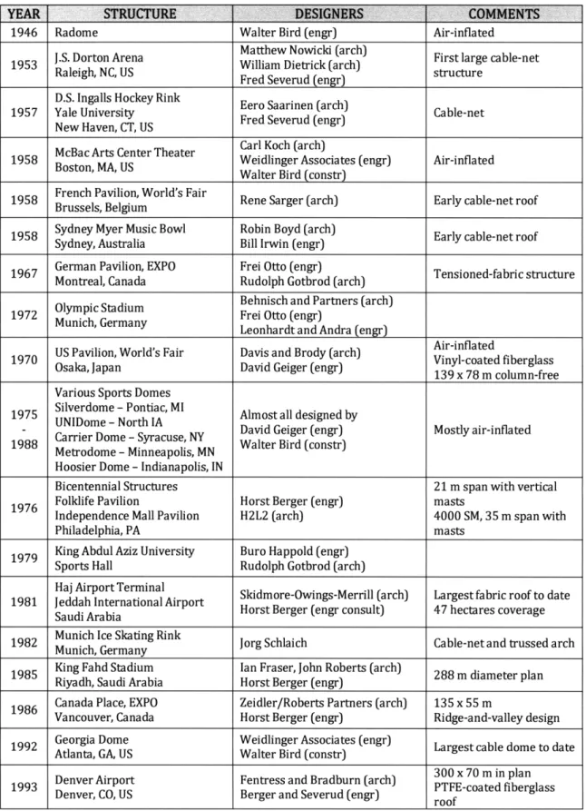
Fabric structures today still possess the same basic attributes of effective coverage and fast construction, but have evolved into large-scale public projects, capable of sheltering huge crowds instead of small family units. Table 1 lists a number of notable fabric structures constructed in the last half-century. Each project brings with it a new set of design requirements and challenges. The following is a brief review of
Figure 1 -Examples of Early Tents selected structures and their contributions to the (Source: Berger, 2005) advancement of fabric structure design and
The Design and Construction of Fabric Structures
Table 1 - Notable Fabric Structures
YEAR STRUCTURE DESIGNERS COMMENTS
1946 Radome Walter Bird (engr) Air-inflated
Matthew Nowicki (arch)
J.S. Dorton Arena William Dietrick (arch) First large cable-net
Raleigh, NC, US Fred Severud (engr) structure
D.S. Ingalls Hockey Rink
1957 Yale University Cable-net
New Haven, CT, US Fred Severud (engr) Cable-net
Carl Koch (arch) McBac Arts Center Theater
1958 Boston, MA, US Weidlinger Associates (engr) Air-inflated Walter Bird (constr)
French Pavilion, World's Fair
1958 French Pavilion, World's Fair Rene Sarger (arch) Early cable-net roof Brussels, Belgium
1958 Sydney Myer Music Bowl Robin Boyd (arch) Early cable-net roof
Sydney, Australia Bill Irwin (engr)
German Pavilion, EXPO Frei Otto (engr)
Montreal, Canada Rudolph Gotbrod (arch)
Olympic Stadium Behnisch and Partners (arch)
1972 Munich, Germany Frei Otto (engr)
Leonhardt and Andra (engr)
Air-inflated
US Pavilion, World's Fair Davis and Brody (arch) Air-inflated
Osaka, Japan David Geiger (engr) 139 x 78 m column-free
139 x 78 m column-free Various Sports Domes
Silverdome - Pontiac, MI
1975 verdome - Pontiac, MI Almost all designed by
David Geiger (engr) Mostly air-inflated
Carrier Dome - Syracuse, NY Walter Bird (constr) Metrodome - Minneapolis, MN
Hoosier Dome - Indianapolis, IN
Bicentennial Structures 21 m span with vertical
Folklife Pavilion Horst Berger (engr) masts
Independence Mall Pavilion H2L2 (arch) 4000 SM, 35 m span with
Philadelphia, PA masts
1979 King Abdul Aziz University Buro Happold (engr)
Sports Hall Rudolph Gotbrod (arch)
Haj Airport Terminal Skidmore-Owings-Merrill (arch) Largest fabric roof to date
Saudi Arabia Horst Berger (engr consult) 47 hectares coverage
Munich Ice Skating Rink
1982 Jorg Schlaich Cable-net and trussed arch
Munich, Germany
King Fahd Stadium Ian Fraser, John Roberts (arch) Riyadh, Saudi Arabia Horst Berger (engr)
Canada Place, EXPO Zeidler/Roberts Partners (arch) 135 x 55 m
Vancouver, Canada Horst Berger (engr) Ridge-and-valley design
1992 Georgia Dome Weidlinger Associates (engr)
Atlanta, GA, US Walter Bird (constr) Largest cable dome to date
Denver Airport Fentress and Bradburn (arch) 300 x 70 m in plan
Denver, CO, US Berger and Severud (engr) PTFE-coated fiberglass
The Design and Construction of Fabric Structures
1.2.1 J.S. DORTON ARENA, RALEIGH, NORTH CAROLINA
Designed by architects William Deitrick, Matthew Nowicki, and engineer Fred Severud, the Raleigh Arena is often cited as the first modern, large-scale, cable-net structure. The famous saddle-shaped roof is made from a set of upwardly-curved cables, which intersect with perpendicular downwardly-curved cables. The upward cables span approximately 95 meters between two intersecting and inclined parabolic arches (Vandenberg). The cable-net roof supports a more traditional roof consisting of rigid insulation and corrugated steel sheets, and creates a 30 meter diameter column-free plan
-(Tripeny). This structure is said to have inspired Frei
Otto to pursue the study of cable-net structures after
Figure 2 -Raleigh Arena visiting Severud's New York office as a student.
(Source: Architectural Record)
1.2.2 GERMAN PAVILION, EXPO, MONTREAL, CANADA
Impressed with the work done by Severud on the Raleigh
Arena, Frei Otto returned to Germany and began to build his
1
famous lightweight structure models. Through theseexperiments, he discovered new ways to structurally support fabric and designed a number of smaller projects in Germany and in Europe. Otto is considered one of the most influential designers in the world of tension fabric structures. His work not only caught the attention of architects and engineers, but also fostered a public
appreciation for them. Figure 3 - German Pavilion Montreal EXPO
(Source: McGill University)
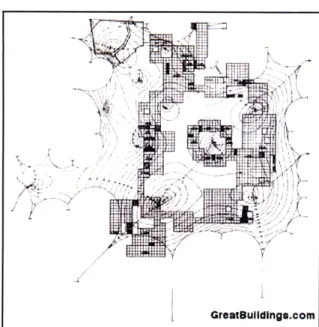
His first large-scale project was the German Pavilion at the Montreal EXPO in 1967. Designed with architect Rudolph Gutbrod, this structure covers a total area of 8,000 square meters, spanning 130 x 105 meters in two directions (see plan in Figure 4). The shape of the roof is determined by a set of support masts, which vary in height from 14 to 38 meters, and anchor points dispersed throughout
The Design and Construction of Fabric Structures the site (German Pavilion, Expo '67, Frei Otto). Though this project is certainly an aesthetic achievement, the structure experienced certain
S/ technical problems related to construction of the
I,.
cable-net and failed during a snow storm only five years after its construction (H. Berger).Figure 4 - Plan View of the German Pavilion (Source: GreatBuildings.com)
GreatBulldlnge.com
1.2.4 U.S. PAVILION, WORLD'S FAIR, OSAKA, JAPAN
The U.S. Pavilion at the 1970 World's Fair in Osaka, Japan is one of the first, large-scale air supported structures constructed. The lightweight roof option was first considered because of the site's poor soil conditions and high exposure to seismic activity.
Designed by architects Davis and Brody and engineered -. .
by David Geiger, the 139 x 78 meter plan forms into the Figure 5 - Plan View of the U.S. Pavilion (Source: Berger, 2005)
shape of a super-ellipse, somewhere between ellipse and
rectangle (see Figure 5 and 6). The super-ellipse is mathematically expressed by the equation:
(x/a)m -bm = 1.
Like many other large-scale fabric structures that are used as exhibition spaces, the U.S. Pavilion in Japan inspired interest in the general Figure 6 - Roof of the U.S. Pavilion public as well as in the engineering and
(Source: Columbia University) architecture industries (H. Berger).
The Design and Construction of Fabric Structures
1.2.5 OLYMPIC STADIUM, MUNICH, GERMANY
The Olympic Stadium for the 1972 Munich Olympic
Games is considered a masterpiece project of Frei Otto; V the culmination of several years of research and design
with the Institute of Lightweight Structures in Stuttgart, Germany. The roof design team included Behnisch &
Partner, and Leonhardt & Andra.
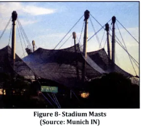
The scale of this project is significant for its time;
covering a total area of 75,000 square meters and using Figure 8- Stadium Masts
(Source: Munich IN)
over 210 kilometers of cable (see initial design in Figure
7). Another ground-breaking aspect of this project is the use of computational models to predict and understand the structure's geometry. These computer models were developed by Professors K
Linkwitz and JH Argyris (Linkwitz).
Figure 7 - Schematic Design
of Olympic Stadium Roof .,
(Source: Vandenberg)
The structural system of the stadium roof included a cable-net spaced at 750 millimeter intervals and suspended from masts, varying in heights up to 80 meters. The whole net was clad with 2.9 x
2.9 meter transparent acrylic panels, separated with continuous neoprene joints to allow for flexible connection to the cables. As a revolutionary construction project resulting from an innovative design process, the Munich Olympic stadium is truly a noteworthy engineering achievement (Vandenberg).
The Design and Construction of Fabric Structures 1.2.5 HAj AIRPORT TERMINAL, JEDDAH INTERNATIONAL AIRPORT, SAUDI ARABIA
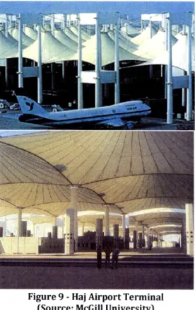
As the world's largest roof structure to date, the Haj Terminal of the Jeddah International airport features a unique and interesting radial tent design. It was designed by architect Skidmore, Owings, Merrill and engineer Horst Berger in 1981. Here again, one can see how fabric structures are efficient for creating visual interest in a publicly exposed space.
For this project in particular, the properties of fabric chosen were of special importance. Located in the middle of the desert, the tent modules shown in Figure 9 were designed to transmit daylight while protecting the huge number of people traveling through the airport on their way to Mecca. The structure consists of 210 square tent
Figure 9 - Haj Airport Terminal units, each measuring 45 meters along its edge cable. The
(Source: McGill University)
cable configuration as well as the overall structural scheme is detailed in the Figures below (H. Berger).
Figure 11 -Radial Cable Configuration (Source: Berger, 2005) wo-"pykn (rar/e interior p~ion
XA
utpenuan cablesI
(upprngas les Figure 10 -Computer Model Illustrating Overall Structural
O -- Scheme (Source: Berger, 2005)
k
Iowe center n ig
The Design and Construction of Fabric Structures
CHAPTER 2: FABRIC MATERIALS
Advances in the design of fabric structures often go hand-in-hand with the development of new, high-performance materials. Materials used for structural fabric satisfy all of the requirements of a typical roof, while maintaining only a fraction of the weight, volume, and cost. These requirements include, but are not limited to, coverage and protection from exterior weather conditions, airtight-ness, waterproofing, fire-resistance, durability, acoustic and heat-control. Sometimes, they must also be able to transmit daylight and be easy to clean (H. Berger).
2.1
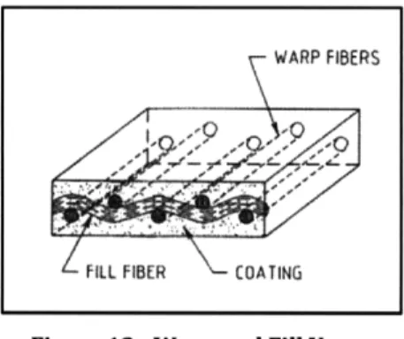
COMPONENTS OF STRUCTURAL FABRICAs implied by their name, the most important and defining component of a fabric structure is the fabric material itself. Structural fabric can be broken down into yarns, which in turn are made of fibers. The basic element of fabric material is therefore the individual fiber. There are a variety of ways to join fibers to create yarn and a number of ways to weave yarn into fabric.
Typically too short and too thin to be used as structural elements, individual fibers must be joined together to become yarn. The fibers can either be bunched in a parallel fashion or twisted together. If they are laid parallel, the resulting equivalent stiffness of the yarn is close to the sum of stiffness
The Design and Construction of Fabric Structures for each fiber. Twisting the fibers together, on the other hand, results in a lower equivalent stiffness because the fibers can elongate more under applied axial loads (Shaeffer).
Like fibers, yarns must also join together in some way to become structural fabric. However, whereas the finished product of joining fibers is a linear yarn, the end result of joining yarns is a two-dimensional fabric sheet. Woven fabric is typically made of two sets of yarn running perpendicular to each other. The initial yarns that run along the length of the fabric are called warpyarns while the ones that thread parallel to these are called fill yarns (see Figure 12). The most common fiber materials used for structural fabric include fiberglass, polyester, nylon, and aramids (or
Figure 12 -Warp and Fill Yarns (Source: Shaeffer) Kevlar) (Testa).
The final step in producing structural fabric is to apply a coating. Coatings are beneficial for many reasons; aside from allowing for a more unified, composite response from the fabric yarns, certain coatings can also protect fabric from weather and dirt, provide fireproofing as well as resistance to ultraviolet radiation (Armijos). Coatings can be applied in liquid form by pouring or spread on and
forced through the fabric. The most common coatings include polyvinylchloride (PVC), polytetrafluoroethylene (PTFE, Teflon), and silicone. It is worth noting that though the coating and
fabric yarns act as a composite material once dry, the coating contributes little to the structural strength properties of the overall fabric (Shaeffer). Table 2 illustrates three different weave patterns along with some advantages and disadvantages of each.
Woven yarns result in fabric that is approximately 3 times the yarn thickness while laid yarn (simply placed on top of each other) results in fabric that is about 2 times the yarn thickness. This means that woven yarn fabrics usually require more coating to obtain a smooth finish.
Coating applications result in two types of bonding: mechanical and chemical. Mechanical action is created by the physical presence of coating material between the threads of fabric yarn. Chemical or adhesion action, on the other hand, is caused by the chemical attachment of coating to fiber material. The pattern of woven yarn is conducive to orthotropic deflection behavior. To induce isotropic behavior, yarns can be pre-stretched before coating.
The Design and Construction of Fabric Structures Table 2 -Advantages and Disadvantages of Different Weave Patterns
Tightly Woven Fabrics
Loosely Woven Scrims Plain Weave
- Plain Weave
Two Layer Thickness High Tensile Strength Very High Tear Strengths
High Mechanical AdhesionHigh Easy to Direct Coat with Liquid Excellent Balance of Tear and
High Tear Strength Systems Tensile Properties
Balance of Mechanical and
Chemical Adhesion
No Mechanical Adhesion,
Low Tensile Strength All Chemical Low Elongation in Both Warp
Coating Between Yarn Openings Low Tear Strength and Fill
> Subjected to Excessive Amount Three Layer Thickness Poor Interaction Between Warp
c of Wear High Filling Strength and Fill Yarns
(Source: Shaeffer)
2.2
BEHAVIORAL PROPERTIES OF FABRIC MATERIALSA proper understanding of elongation and elastic properties of fabric materials is essential to creating a desired shape. The application of new materials can be frustrating because if one of the properties is not sufficient, it usually requires the development of an entirely new fabric, with different yarns and weaving techniques. Sometimes, the resulting new fabric can have a totally different set of properties than the ones previously specified (Bird).
Conventional structures often require lower factors of safety because the materials they use have more dependable strength properties. In contrast, fabric materials exhibit unreliable behavior and low durability, as properties can change drastically over time as a result of weathering, UV degradation, and repeated loading (Shaeffer).
-The Design and Construction of Fabric Structures
2.2.1 TEARING AND TENSILE STRENGTH
rearing and tensile strength describe a fabric's ability to carry load along the plane of the fabric. While tensile strength is a measure of fabric stretching from opposite ends, tearing strength refers to local failure, when forces are applied at one location in opposite directions. Figure 13 shows a number of tests used to determine these properties.
The tear and tensile strength of fabric are indirectly related; as tensile strength increases, tearing strength decreases. This relationship is analogous to cutting a string; a taut string is easier to cut than a slack one. Similarly, a fabric that is capable of carrying higher planar stresses will tear more easily. -- 7Mt T d.e r Grmb Teals T. =Ah 0411) n o mrp ar, 5ao 1Pt -~ 4"' ait Blal Tenle tet
,( 1 to
Q iSD
1.2LEI
'Asvoo T.,
(AShI D3M)
Tensile strength varies greatly between the Figure 13 -Various Tests to Determine Material Properties (Source: Huntington, 2004)
warp and fill directions, and is usually
stronger in the warp. It also changes drastically from initial loadings to repeated loadings. Two types of tests exist to measure the tensile strength of fabric materials; both are strip tensile tests, but one is uniaxial and the other is biaxial (see Figure 13). The biaxial test more accurately measures the tensile strength because fabrics exhibit orthotropic behavior in two directions.
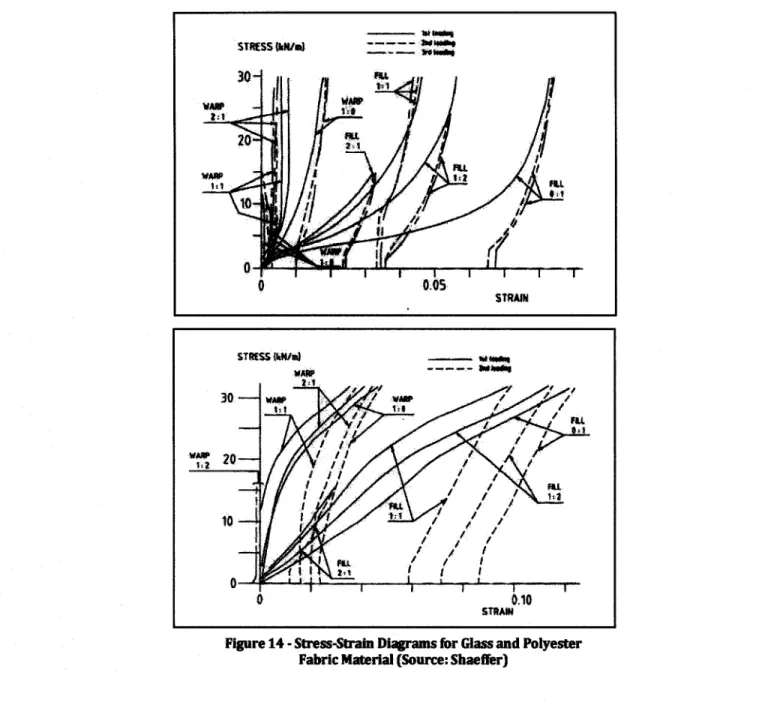
The stress-strain curves in Figure 14 yield certain conclusions about fabric material strength behavior:
- The behavior of warp yarns varies greatly from fill yarns. Both vary with the ratio of warp to fill stress.
- All fibers displace more during second and subsequent loadings as opposed to first loading. - All fibers exhibit nonlinear stress-strain behavior
The Design and Construction of Fabric Structures
STKSS Mu6m)l . .. . :ar3---
-STRAIN
Figure 14 - Stress-Strain Diagrams for Glass and Polyester Fabric Material (Source: Shaeffer)
2.2.2 STRETCHING AND DIMENSIONAL STABILITY
As mentioned previously, the weaving process of fabric results in a material that elongates and deforms a great deal. The main way to mitigate this problem is to pre-stretch or pre-tension the fabric. This can be done to the fabric as a whole before installation or during the weaving process to individual fibers, in which case the force in warp and fill fibers can be adjusted to produce equal deflection in both directions. Fabrics tend to have more strength in the straight, warp direction rather than the "crimped" fill direction, and can often become dimensionally unstable as a result of crimp interchange (Huntington).
The Design and Construction of Fabric Structures Other factors can affect the dimensional stability of fabric material. These include changes in temperature and water content. Increases in temperature will increase fiber elongation as a function of the material's coefficient of thermal expansion. Water is bad for fabric materials for a number of reasons. In addition to promoting freeze-thaw action, water also carries micro-organisms that degrade the material over time. For these reasons, water-proofing is an important function of fabric coatings (Shaeffer).
Stretching and dimensional stability are significant considerations because fabric membranes must always remain in tension. If any section of a fabric loses tension, it "bags" and "flutters" and can no longer contribute to the load-resisting structural system (Armijos).
2.2.3 ULTRAVIOLET RADIATION PROTECTION
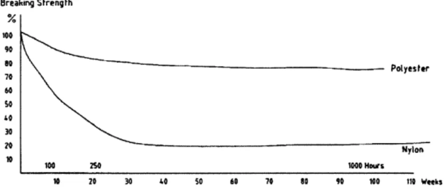
Many fabric structures degrade with exposure to UV light. Though glass is not significantly affected, tests have shown that polyester loses 20% and nylon 90% of its strength when exposed for 110 weeks (see Figure 15). UV protection can be achieved with light-resistant additives in the fiber material or UV absorbers in the coating (Shaeffer).
Breaking Strength 00 Polyester 70 60 2 Nylon 100 2SO 1000 Hoiws 10 20 30 40 50 60 70 80 90 100 110 Webek
Figure 15 -Degradation of Fabric Material Subjected to UV Radiation (Source: Shaeffer)
2.2.4 FIRE PROTECTION
Fireproofing is a major consideration in the design of fabric structures. Several common fire tests and standards exist for fabrics and other textile materials. These include:
- The National Fire Protection (NFPA) 701 - Fire Tests for Flame-Resistant Textile and Films
- The American Society for Testing and Materials (ASTM)
o E84 - Surface Burning Characteristics of Building Materials (Flame Spread Test) o E108 - Fire Tests of Roof Coverings
The Design and Construction of Fabric Structures o E136 - Behavior of Materials in a Vertical Tube Furnace at 750 'C
2.2.5 TRANSLUCENCY AND THERMAL RESISTANCE
Fabric materials feature several properties that render them effective in warmer climates. These include low insulating ability, low thermal mass, high reflectivity of light, and low translucency. Translucency is an important material property of architectural fabrics because it has both aesthetic and technical implications: allowing natural daylight into a building space and resulting in higher energy savings. Fabrics are available in a range of translucency, from as little as 1% to as much as 95%, though the most commonly-used fabric materials can only achieve about 25%.
Similar energy cost savings can be achieved by adjusting the thermal resistive properties of fabric. Thermal insulation provided by fabric materials can vary from the equivalent of as little as a single pane of glass or as much as conventional wall and roof structures (Armijos).
2.3 COMPARISON OF COMMON FABRIC MATERIALS AND COATINGS
As mentioned before, the most commonly used fabric materials are polyester, nylon, fiberglass, and aramid (or Kevlar) while the most commonly used coatings are PVC, PTFE, Teflon, and Silcone. The most popular combination of fiber and coating are PVC-coated polyester, PTFE-coated fiberglass, and Silicone-coated fiberglass.
Polyester fabric has a lower tensile strength, but greater modulus of elasticity and stiffness than nylon fabric. This lower strength in polyester can be considered a fair trade for the lower deformations resulting from its higher stiffness. Though polyester fibers are more susceptible to ultraviolet radiation than nylon fibers, they are also easier to protect, rendering the polyester fabric more durable overall. Both polyester and nylon are more flexible than glass and aramid fabrics. Glass fabrics boast higher strength and extensional modulus of elasticity than nylon and polyester, but also exhibit brittle breaking behavior. Glass fibers are usually made very small to compensate for this drawback. Extra care is taken when folding or rolling glass fabrics during construction transport and erection to protect from damage due to repeated flexure (Shaeffer).
2.3.1 PVC-COATED POLYESTER
PVC-coated polyester fabric is the oldest and one of the most commonly used materials on fabric structures. It has a high tensile and tear strength but low durability as it tends to deteriorate from UV radiation. It also exhibits creep behavior, losing significant levels of pre-stress over time and
The Design and Construction of Fabric Structures sometimes requiring membrane re-stressing. Their tendency to retain dirt can be overcome with the application of fluropolymers on top of the PVC coating (Lewis, Tension Structures Form and Behaviour). Though this material was popular in the 1960's, it has since been surpassed by glass fiber fabrics, partly because many consider its low durability and lifespan of 10-15 years a barrier to application as permanent structure (Huntington, The Tensioned Fabric Roof).
2.3.2 PTFE-COATED FIBERGLASS
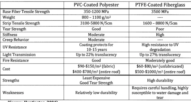
Teflon-coated glass and silicone-coated glass fabrics have considerably higher tensile strengths, but poor tear strengths in comparison to PVC-coated polyester. They also exhibit less creep and require minimal maintenance, though water damage is sometimes a serious concern. Because glass is more susceptible to brittle failure, PTFE-coated fiberglass must be handled with care during transport. Silicone-coated fabrics are more flexible and therefore less brittle than Teflon-coated fabrics (Lewis, Lightweight Tension Membranes - An Overview). Table 3 is a brief comparison of two commonly used fabric materials. It is worth noting that fiberglass is typically much more expensive than polyester both as a raw material and as a finished roof application (Huntington, The Tensioned Fabric Roof).
Table 3 - Comparison of Commonly-Used Fabric Materials
PVC-Coated Polyester PTFE-Coated Fiberglass
Base Fiber Tensile Strength 350-1200 MPa 3500 MPa
Weight 800 - 1100 g/m2 ....
Strip Tensile Strength 3100-5800 N/5cm 1600 -8800 N/5cm
Tear Strength Good Poor
Stiffness Moderate High
Creep Behavior Moderate
----Coating protects for High resistance to UV
10-15 years degradation
Light Transmission Up to 22% translucency Up to 27% translucency
Fire Resistance Good Moderately good
$90-$150/m2 (fabric) $60-$80/m2 (unfabricated)
$400-$700/m2 (entire roof) $500-$1000/m2 (entire roof) Least Expensive
Strengths Good Tear Strength High durability
Requires careful handling, highly
Weaknesses Relatively low durability susceptible to water damage and
tear
(Source: Huntington, 2004)
--The Design and Construction of Fabric Structures
2.4
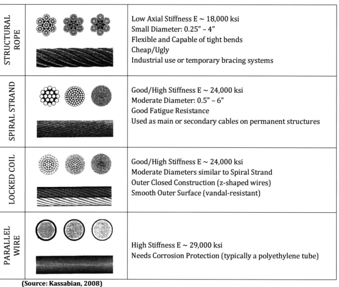
STRUCTURAL CABLEStructural cable was first developed and popularized for use on suspension bridges in the early 20th century. Capable of reaching strengths three to four times larger than standard structural steel sections, these flexible elements are often used to support tensioned fabric membranes, either as edge boundaries or as a way to subdivide the membranes. When placed in the middle of the fabric surface, cables will help to reduce the span of fabric. Because they are much stiffer than the fabric material, they act as rigid support points from which the fabric can span. Table 4 is a summary of different types of commonly used structural cable with some general advantages and disadvantages of each (Kassabian). The connection of fabric to cable is described in detail in Section 4.1.2.
Table 4 - Properties of Different Types of Structural Cable
Low Axial Stiffness E ~18,000 ksi Small Diameter: 0.25" - 4"
SFlexible and Capable of tight bends
l
Cheap/UglyIndustrial use or temporary bracing systems
Z Q Good/High Stiffness E ~ 24,000 ksi
Moderate Diameter: 0.5" - 6"
)Good Fatigue Resistance
Used as main or secondary cables on permanent structures
SGood/High
Stiffness E - 24,000 ksiModerate Diameters similar to Spiral Strand Outer Closed Construction (z-shaped wires)
OU Smooth Outer Surface (vandal-resistant)
_.q
CHigh Stiffness E ~ 29,000 ksi
.<
I:
Needs Corrosion Protection (typically a polyethylene tube)The Design and Construction of Fabric Structures
CHAPTER 3: DESIGN AND ANALYSIS
Traditional building design involves the definition of initial parameters such as member sizing and spacing, the analysis of these members under applied loads, and then the adjustment of the initial parameters under strength or displacement limitations. This procedure usually requires a few simple iterations and can be completed with classical (and often linear) analysis methods. Furthermore, as the majority of buildings in the last century have been designed in this way, the behavior of conventional building systems is well understood and documented. The design and analysis of fabric structures, on the other hand, differs greatly from this traditional process, having a new set of design loads and considerations. Because initial geometric parameters can change so drastically, their analysis often requires multiple iterations with newer computational methods. In fact, the overall form of a fabric structure changes so much that this process is commonly referred to as "shape" or "form" finding.
This chapter begins with general considerations for the design of fabric structures and then explains the basics of how fabric structures work. The rest of the chapter presents and discusses the various numerical methods available for their analysis.
The Design and Construction of Fabric Structures
3.1
DESIGN CONSIDERATIONSAs mentioned previously, the design of fabric structures comes with several considerations that need not be made for conventional structures. These include certain load and climate conditions, availability of material and labor, acoustic performance, fire protection, energy use and lighting, as well as material maintenance, durability, and inspection. The material considerations have already been discussed in Chapter 2.
3.1.1 DESIGN LOADS
Though several building codes stipulate design load requirements, the standards are usually intended for stiff and straight, conventional structures. ASCE (the American Society of Civil Engineers) is currently adapting their standards for application to tensioned fabric roofs. The following is an explanation of how load considerations will differ for fabric structures.
Being much lighter than conventional structural members, fabric roof structures and accompanying cables or ties incur only a small fraction of typical dead loading (generally less than 50 N/m2). For this same reason, seismic loads, which vary with the mass of a building, usually do not constitute a serious concern in the design of fabric structures.
Roof live load code requirements were determined based on the assumption of heavy rooftop machinery and other usages that do not apply to a fabric roof. Indeed, with their curved forms and high deformability, fabric roofs are usually inaccessible to people except for maintenance and repair. However, current code provisions do not exempt fabric roofs and they are therefore designed with normal live loads (Huntington, The Tensioned Fabric Roof).
Wind loads usually control over other types of loading in the design of fabric structures. Though wind load specifications are available in local building codes, the behavior of fabric roofs under wind is unpredictable enough as to warrant the use of wind-tunnel testing in many situations. Depending on the direction of wind and the geometric properties of the fabric, wind can either act as inward pressure or outward suction, in which case the suction will tend to counteract downward gravity loads.
In some regions, snow and rain will govern over wind loading. The curvature and natural flexibility of fabric membranes can lead to a lot of uneven snow distribution. It is important to note that concentrated loads like high snow drift will often be more critical than large uniformly distributed
The Design and Construction of Fabric Structures wind pressures. Melted snow or rain also tends to pond in the downwardly curved sections of membrane. For this reason, drains and snow-melting techniques are often incorporated into their design (Krishna).
In general, temperature loads do not affect fabric structures.
3.2 How FABRIC STRUCTURES WORK
Conventional structures depend on gravity and internal rigidity for load transfer and for stability. Beams and columns in these structures can resist axial, shear, and bending stresses. Fabric structures, on the other hand, are so lightweight that gravity does not have any serious effect. Furthermore, fabric elements transfer all loads axially, as they have negligible bending and shear stiffness. They therefore gain stability from their curved form and internal axial prestressing alone.
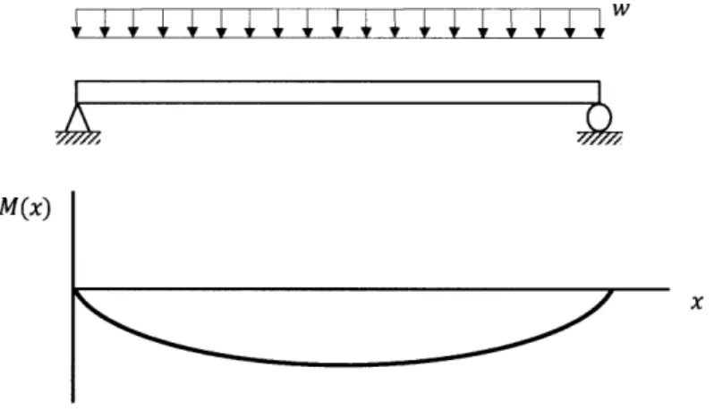
As mentioned before, the basic structural element of a fabric membrane is a set of cables running in perpendicular directions. Discussing the behavior of a single cable can therefore help to illustrate certain behavioral properties of a fabric membrane. To better understand this behavior, first consider the uniformly loaded beam and its bending moment diagram in Figure 16.
M(x)
Figure 16 - Uniformly Loaded Beam and Moment Diagram
The shape that a cable takes under this same load is considered optimal because it follows the bending moment diagram. When considering a cable's self weight only, the shape it takes is called catenary (although this term is often used when describing the natural shape resulting from any applied load). Because a cable cannot resist shear and bending, it will therefore deflect in such a way as to carry applied loads in axial tension only, all the while doing so with much less material than a straight beam under the same loads. Now consider the uniformly loaded cable and deflected
The Design and Construction of Fabric Structures shape in Figure 17. w is the load per unit length, L is the total length of cable, h is the maximum vertical deflection at midspan, and H and V are horizontal and vertical reaction forces, respectively.
W 5_ i _1~~~~ v" -- ~ L 1 H4-71 L/2
Figure 17 -Uniformly Loaded Cable
Equilibrium in the vertical direction yields:
wL
V=
2
Because cables cannot resist bending, the sum of moments about any point will be equal to zero.
Y Mmidpoint = 0
H(h)+w )V = 0
wL2
H= 8h
8h
And the force in the cable is:
F = V2 + H2
One can observe from these initial cable expressions that the sag or vertical deflection of a cable varies with the horizontal reaction force. This is the idea behind pre-tensioning in fabric membranes. Adjusting the horizontal tension force is the primary means of limiting membrane
The Design and Construction of Fabric Structures deflection. Applied loads will also be carried by the vertical "pins" (typically rigid supports such as masts or metal frames).
Depending on specified boundary conditions and internal prestressing, fabrics can either form into an anticlastic shape with negative Gaussian curvature or a synclastic shape with positive Gaussian curvature. The term anticlastic refers to the opposing directions of perpendicular fiber elements. Joining together to form a saddle-like shape, these elements exert equal forces on each other and
internally brace against themselves. Synclastic same direction like a balloon. In the design of fabric structures, upwardly curved elements are usually called "ridge" cables while downwardly curved ones are "valley" cables. The minimum number of anchor points needed
for any section of fabric is four. Three points are insufficient because the resulting surface is a simple, flat triangle; as mentioned in the previous discussion about cables, fabric elements gain stability with curvature. The four
shapes consist of elements that are curved in the
Figure 18 - Examples of Various Four Point Structures (Source: Berger, 2005)
point structure is therefore the most basic element of a fabric structure. It can be created with an endless number of boundary conditions and joined together to make a variety of interesting shapes and patterns. Figure 18 illustrates only a small sampling of the types of structures that can be created with the four point structure (H. Berger).
3.3 ANALYSIS METHODS - THEORY AND METHODS FOR SHAPE-FINDING
Analysis models for conventional structures assume a linear relationship between applied forces and displacements. These linear models can accurately describe a structure's shape, but are limited to a range of small displacements. Conversely, the design and analysis of fabric structures requires a thoroughly non-linear approach, modeling large deformation behavior through the use of iterative numerical methods (Lewis, Tension Structures Form and Behaviour).
The Newton-Raphson method is a classical approach to the analysis of nonlinear structures, which does not apply well to the behavior of fabric because convergence is slow and sometimes does not happen at all. However, Newton-Raphson works better when an initial estimate of shape or geometry is specified. Newer analysis methods have been developed for the direct application of
<Air
/
The Design and Construction of Fabric Structures analyzing cable-net and tensioned fabric structures. These include the Grid Method and the Force Density Method, which are both used to estimate initial system geometries before applying Newton-Raphson. Another nonlinear analysis that can be applied to fabric structures is the Dynamic Relaxation Method (Bradshaw). The theory behind each of these methods is described in detail in the following sections.
3.3.1 REVIEW OF LINEAR STRUCTURAL ANALYSIS
To better understand these methods, the classical theory of linear analysis is first reviewed with the help of simplified example problems.
9"E,A
L
Figure 19 -Axially Loaded Element
Figure 19 illustrates a single element with initial length L, cross-sectional area A, and modulus of elasticity E. An applied axial load P results in an elongation that is linearly related by the axial elastic stiffness, Ke = EA/L . This relationship can be described as:
P = KeU
where u is the elongation in the direction of applied load.
In a two-element system, it becomes more convenient to label displacements as a nodal vector, 5 where u, v, w are displacements in the x, y, and z directions, respectively. With this notation, a global stiffness matrix K and nodal load vector P can also be defined and the new force-displacement relationship is:
{P) = [Ke]{6)
ky
k12 k13-1x
{} = , [Ke] = k21 k2 2 k2 3 , P Py
Wk3 3 k3 2 k3 3- Pz
This matrix notation applies to a single node with three degrees-of-freedom (again in the x, y, and z directions). The entry kij represents the force at degree-of-freedom i due to a unit displacement at
The Design and Construction of Fabric Structures degree of freedom j. These matrices and vectors will be expanded to accommodate the number of nodes in the system. In general, these terms have the following dimensions: {6) = [n x 1], [Ke] = [n x n] , {P} = [n x 1], where n is the number of degrees of freedom in the system. Note that the global stiffness matrix is formulated from individual member stiffness and therefore accounts for all members that will affect a specific node or degree-of-freedom (Lewis).
Though the stiffness matrix method works well for conventional structural elements such as trusses, beams, and columns, one should remember that it assumes a linear relationship between force and displacement and therefore, does not apply to the behavior of structural fabric.
3.3.2 TANGENT STIFFNESS METHOD
Structural fabric exhibits large deformation and geometrically non-linear behavior. Because of this, it requires different methods of analysis, which tend to be numerical and iterative. The following describes the theory behind the tangent stiffness method (sometimes known as the transient stiffness method), which derives from the linear stiffness method discussed in the previous section. The main reason that linear methods do not apply for large deformations is because the stiffness matrix depends on initial member geometries. When the members in a system deform by a significant amount, the stiffness matrix for the system will also change. The tangent stiffness method attempts to account for this discrepancy in the following way.
Begin by defining initial geometry vector, {X}i on which initial stiffness is based. The displacement resulting from this initial stiffness will be:
(6}si+ = [K]i' (P}
And the new system geometry is:
(X}i+l = tX}i + {6Ii+i
From this updated geometry, one can find a new stiffness matrix, [K]i+,. This stiffness combined with displacement will yield a set of internal forces, (Pi)} which differ from the set of external forces.
(Pin)i+1 = [K]- (6}j+
~---The Design and Construction of Fabric Structures For large displacements, tPin) ({P}. Define an error term or residual, (R} and then an incremental
displacement vector, {A6}:
{R} 1 = (P) -(P nh+
(AS},i+ = [K][1 {R)}i+1
At this point, the geometry vector is updated by the incremental displacement vector and more iterations can be performed until the residual vector converges on zero.
3.3.3 GRID METHOD
As mentioned previously, the grid method is a simple approach to the nonlinear analysis of fabric structures. Initially developed by Siev and Eidelman (1964), the grid method begins by laying a flat grid underneath the structure. In doing so, it assumes that the structure is an orthogonal cable-net with equidistant node spacing. Another simplifying assumption is that nodes do not undergo horizontal displacement; individual joints will move in the vertical direction only.
In the example problem in Figure 20, one cable pulls up while the
P other pulls down. It is important to note that the position of the node is not affected by prestressing forces. If an external horizontal load, H is applied, the cable-net remains in equilibrium because the horizontal component at each node is equal to H. However, if an external vertical load, P is applied, the load in the top cable
Figure 20 -Basic Cable-Net increases and the load in the bottom cable decreases. Therefore, Element
because vertical equilibrium is the only concern, each node has one unknown and the problem is reduced to a set of linear equations, of which the solution is the vertical position or elevation of each node (Bradshaw).
Remember that the grid method is only used to estimate an initial shape or geometry that will be used in conjunction with the Newton-Raphson Method.
3.3.4 FORCE DENSITY METHOD
The force density method is another analytical procedure developed for the analysis of nonlinear structures. The basic idea behind this method is that the force in a structural member can be
The Design and Construction of Fabric Structures described by multiplying the member force by a unit vector in the direction of the member. The following formulation describes the force components of a member, i in the x, y, and z directions.
F
(Fx = - (XA - XB)
(Fi) (Y - YB)
(F,)z (ZA - ZB)
Li
Note that the force density is equal to the force in the member divided by its length, Fi/Li . One can
see from these equations that if the force density were set to some constant, the force in the member would be a linear function of the coordinates XA,YA ,ZA,XB, YBZB. Because of this, equilibrium equations at any node will be reduced to a set of linear equations with force as a function of length (Schek).
3.3.5 DYNAMIC RELAXATION METHOD
The dynamic relaxation method is widely accepted as a successful tool in the analysis of cable-net and tension fabric structures. Initially developed in the 1960's for the study of concrete nuclear vessels, the method was first adapted for application to cable structures by Day and Bunce in 1970. The method begins by discretizing a given system into concentrated or lumped masses at specified points (in a cable-net, it is convenient to lump mass at the nodes or joints). The next step is to
model the dynamic response of these discrete masses. The mathematical procedure, excerpted from (Lewis), is outlined below:
Begin with the equation of motion for the jth node in the ith direction.
Pi => KS ]i + Mji j + C ji
where Pji represents a vector of externally applied loads, [Z KS]ji represents a vector of internal
loads, C is the coefficient of viscous damping, and Si, S6i are the nodal accelerations and velocities.
Next, define the residual or error between internal and external loads, R
Rji = Pj - [KS]i = jsii + csa
The Design and Construction of Fabric Structures Use the centered finite difference approximation to represent acceleration as a function of velocity over time step interval, At. In this expression, the velocity is represented as an average over the same time interval. For simplicity, the subscriptji is omitted from the following equations.
= n+1/2 _ n-1/2 I n+1/2 + n-1/2
Rn = M At + C 2
Rearranging the above equation will yield the following expression for velocity, which can then be used to estimate displacement at time n + 1.
MC
(At
2+ + C
At 2 !t 2
6n+1 = 6n + Sn+1/2At
These steps represent one iteration of the dynamic relaxation method. They are repeated until the residual term converges on zero (i.e. the internal forces match the external forces).
The Design and Construction of Fabric Structures
CHAPTER 4: CONSTRUCTION CONSIDERATIONS
The constructor of fabric structures has a more important role to play than those of conventional structures, because they are dealing with relatively new materials, methods, and technologies. Indeed, fabric roof design is often considered so special that it falls under a separate contract from the main structural system of a building; clients will even sometimes appoint a different structural engineer for the fabric and for the main structure. More often than not, the design of fabric structure is limited by manufacturing capabilities. A fabric contractor must therefore be chosen with care.
In a seminar presented at the ASCE Spring Convention and Exhibit in April 1977, Walter Bird spoke of the role of the fabricator in implementing large-scale fabric structures. Though much has changed in the practice of constructing fabric structures since then, many of the same basic procedures and considerations still apply today. According to Bird, it is the responsibility of the fabricator to help architects and engineers in the material selection process, informing them of special material properties as well as advising them on practical patterning and pre-stressing techniques (Bird).
The Design and Construction of Fabric Structures This chapter first details a number of common connections used in tensioned fabric structures, and then discusses the patterning, erection, installation, and pre-stressing process.
4.1 TYPES OF CONNECTIONS
The design of connections in fabric structures often requires careful and thorough consideration. Unlike connections in conventional buildings, they play a crucial role in the creation of architectural form and concept, as the geometry of a fabric roof is entirely dependent on the proper placement and design of these connections. Furthermore, they are often exposed to view and must therefore be constructed with aesthetics in mind. One of the most important considerations when designing fabric connections is the stress concentration that may occur in the local area surrounding it. Being highly sensitive to concentrated applied forces, clamps, cables, and seams should almost always fully develop stresses into the fabric.
Fabric connections also need to be designed to account for load path, understanding that loads will tend to follow the stiffest path. In the case of a fabric membrane, applied loads will travel through the flexible membrane into less flexible interior or edge cables and then into the stiff and rigid supports. The following sections present various schemes for the connection of fabric elements. 4.1.1 FABRIC TO FABRIC
After fabrics are patterned and cut, they can be joined together in a number of ways. These
include heat sealing, gluing, and sewing. Lap i¢41It
seams are typically laid out in a "shingle" like FABRIC (TOPSIDE) pattern, with higher pieces of fabric draped WELOEO DR
CEMENTEO SEAM over lower ones to facilitate water run-off.
Seam strengths are dependent on coating Figure 21 -Standard Lap Seam (Source: Shaeffer)
adhesion and seam widths (Shaeffer). Figure 21 illustrates a standard lap seam.
4.1.2 FABRIC TO CABLE
Fabric to cable connections are needed when structural cables help to support a fabric membrane. One-sided connections are made when the fabric terminates at an edge cable and two-sided connections occur when the fabric is sectioned by the cable on both sides. Sectioning or subdividing