HAL Id: hal-02912914
https://hal.archives-ouvertes.fr/hal-02912914
Submitted on 7 Aug 2020
HAL is a multi-disciplinary open access
archive for the deposit and dissemination of
sci-entific research documents, whether they are
pub-lished or not. The documents may come from
teaching and research institutions in France or
abroad, or from public or private research centers.
L’archive ouverte pluridisciplinaire HAL, est
destinée au dépôt et à la diffusion de documents
scientifiques de niveau recherche, publiés ou non,
émanant des établissements d’enseignement et de
recherche français ou étrangers, des laboratoires
publics ou privés.
Flexible Textile Antenna Design with Transparent
Conductive Fabric Integrated in OLED for WiMAX
Wireless Communication Systems
Soukaina Sekkal, Laurent Canale, Adel Asselman
To cite this version:
Soukaina Sekkal, Laurent Canale, Adel Asselman. Flexible Textile Antenna Design with Transparent
Conductive Fabric Integrated in OLED for WiMAX Wireless Communication Systems. 2020 IEEE
International Conference on Environment and Electrical Engineering and 2020 IEEE Industrial and
Commercial Power Systems Europe (EEEIC / I&CPS Europe), Jun 2020, Madrid, Spain. pp.1-4,
�10.1109/EEEIC/ICPSEurope49358.2020.9160757�. �hal-02912914�
978-1-7281-7455-6/20/$31.00 ©2020 IEEE
Flexible Textile Antenna Design with Transparent
Conductive Fabric Integrated in OLED for WiMAX
Wireless Communication Systems
Soukaina Sekkal
Optics and Photonics Laboratory Université Abdelmalek Essaadi
Tetouan, Morroco [email protected]
Laurent Canale
IEEE Senior Member LAPLACE, Université de Toulouse,
CNRS, INPT, UPS,
Toulouse, France [email protected]
Adel Asselman
Optics and Photonics Laboratory, Université Abdelmalek Essaadi
Tetouan, Morroco [email protected]
Abstract— A new flexible antenna made entirely from a
transparent conductive fabric VeilShield has been designed to be integrated in OLED light sources as well as flexible or rollable displays. It was layered on a 100% polyester support with a thickness of 1.5 mm and achieves a good adaptation and high gain. The simple and flexible patch antenna has been designed to operate at two frequencies bands: the first one operating at 3.15 GHz in S-band and the second operating at 3.5 GHz for WiMAX wireless communication systems. We have evaluated and tested its performances, including the reflection coefficient, the gain, the radiation pattern and the surface current distribution, with gain values of 5.76 dB and 1.66 dB respectively. This article demonstrates the applicability of the material proposed for the design of flexible antennas integrated into OLED light sources while maintaining gain performance comparable to conventional planar antennas.
Keywords—flexible antenna, OLED, VeilShield, wireless communication, 100% polyester, transparent conductive fabric.
I. INTRODUCTION
The growing need for data throughput will require diversification and multiplication of communication channels which will lead to the development of antennas integrated into existing products. On the other hand, due to their long lifespan, easy-to-make products, efficiency and high quality of light, OLED technologies are likely to be the next generation of light sources [1]. Among its many advantages that can be useful for lighting as well as displays, let us mention that they are also flexible and even rollable.With the development of smart windows, these will integrate OLED as well as other versatile functions [2, 3]. In the same spirit of integration, we present here the first technological step of a flexible antenna aiming at being integrated into OLED light sources. Textiles have emerged in recent years as promising materials for the development of antennas. This allows the many smart wearable wireless electronic systems to communicate through wireless networks like WLAN and WiMAX.
A lot of research has been performed on the various materials for the construction of wearable antennas since 1997 when wearable antenna was initially defined as an antenna designed to be an integral part of clothing [4, 5]. A
flexible antenna is a key component in emerging wearable wireless electronic devices which often should have additional characteristics such as flexibility and robustness which demands the consideration of flexible non-conventional materials to replace traditional printed circuit boards.
Significant amount of research efforts can be found in the literature for nonconventional materials which opens up new trends in wireless communications such as conductive fabrics [6], copper tapes [7], silver paste [8], conductive ink [9], and conductive threads [10] are used to form the antenna radiating element and polymer, using cotton and felt [6] as substrate. These materials are widely used in industry, for various applications in fields ranging from energy to electronics or security. They are for example required in the manufacture of touch screens (telephones, tablet PCs, GPS, game consoles, automatic ticketing ...).
In this work, the flexibility was integrated to design a fully fabric flexible antenna employing a transparent conductive fabric VeilShield and insulating 100% polyester fabric. The simple patch antenna has been proposed for high gain operation at 3.15GHz and to be used for WiMAX Wireless communication systems at 3.5GHz.
II. MATERIAL CHARACTERISTICS A. Conductive Fabric
For the rectangular patch, radiating element and the ground plane of the antenna conductive parts we used the parameters of the transparent fabric VeilShield.
This fabric consists of woven meshed polyester fibers, coated with nickel/zinc-blackened copper for greater corrosion resistance. Its thickness is 0.057 mm, it has a very low sheet resistance of 0.089 Ω/sq. The electrical conductivity was calculated based on :
(1) Where and are the sheet resistivity and the sheet thickness respectively.
The calculated theoretical transparency of the fabric is , using [11]:
(2)Funded by French Ministry of Europe and Foreign Affairs and Moroccan Ministry of Higher Education and Scientific Research as a part of Program Hubert Curien “Maghreb” MELINA (Mastering Efficient Lighting in North Africa) granted to L.C.
Where p is the pitch of the mesh with a size of about 620 µm and s was the strip width had a size of 90 µm, as shown in Fig.1.
Fig.1. Transparent fabric tissue (a) zoomed view and (b) photo. [12]
B. Dielectric Properties of 100% Polyester
This fabric or textile is made of polyester threads or fibers. Its dielectric constant is Ɛ = 2.85, while the loss tangent is δ = 0.02. In addition, polyester is very stable to humidity and to attack moisture, flexible, even having greater resistance and resilience of the deformations of 40 % [13].
III. ANTENNA DESIGN
One fully fabric antenna was designed to operate at 3.15 GHz and 3.5 GHz measured at ( ) to
demonstrate the proposed concept of 100 % polyester embedding of transparent fabric to design flexible antennas.
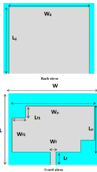
The antenna had a size of , whereby the microstrip feed line is applied with a width Wf = 4.12 mm to ensure a 50 Ω input impedance. The antenna geometry and its parameters are shown in Fig.2 and Table I, respectively. For simulation and design CST (Computer Simulation Technology) Microwave Studio 2017 was used.
TABLEI. DIMENSIONS OF THE PROPOSED DESIGN Design Parameters Value(mm) Wp 60 Lp 35 Wg 58 Lg 52 Lf 10 Wf 4.12 Lf1 9 Wf1 10
In the proposed antenna design, a full ground plane is used to reduce back radiation. Polyester was chosen for antenna substrate due to its high resistance to air pollutants, toughness and good elastic recovery strain [13].
Fig. 2. Configuration of the flexible antenna using microstrip line
IV. SIMULATION AND RESULT
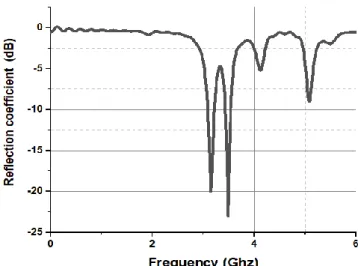
The performance of the flexible antenna in terms of reflection coefficient and gain is demonstrated in Fig.3 and Fig. 4, respectively.
From the reflection coefficient of the proposed antenna, it appears that the antenna is exhibiting resonance at two frequencies: the first operating at 3.15GHz, suitable for S band applications (2 to 4GHz), the second at 3.5 GHz for WiMAX Wireless communication systems.
The variation of the gain of the flexible patch antenna is represented in Fig.3 in the frequency band from 3 GHz to 3.6 GHz.
It can be observed that the proposed antenna has a high gain of 5.76 dB at 3.15 GHz and a gain of 1.66 dB at 3.5 GHz. The gain tends to decrease as the operating frequency increases. This results from increase with frequency of the dominant losses of the conductive fabric. It can be noted that the overall performance of the proposed design in terms of gain at the frequency 3.15Ghz and 3.5GHz is better than in other bandwidths.
The 3D radiation pattern for the proposed antenna is shown in Fig. 5, illustrating the orientation and the level of the main lobe. This antenna exhibits an omnidirectional radiation pattern with a maximum gain of 1.66 dB.
Fig. 3 Performance of the proposed fully fabric and flexible antenna in terms of reflection coefficient.
Fig. 4. Performance of the proposed fully fabric and flexible antenna in terms of Gain.
Fig. 5. The 3D radiation pattern for the proposed antenna at 3.5GHz.
The far field radiation patterns of the proposed patch antenna in E plane and H plane at the frequency 3.5GHz are
illustrated in Fig. 6. In general, the figure depicts stable power distribution in the different radiation planes at the resonant frequency 3.5 GHz.
Fig.6 (a) shows E-plane radiation pattern at 3.5 GHz frequency, its main lobe magnitude is 1.07 dB. It can be seen that E-plane radiation pattern isclose to omnidirectional.
Fig.6 (b) shows the global visualization of the H-plane radiation pattern at 3.5 GHz frequency, its main lobe magnitude is -1.1 dB. Characteristics of radiation pattern are given in TABLE II.
Fig. 6. Simulated radiation pattern of the proposed antenna at 3.5 GHz (a) E-Plane, (b) H-Plane
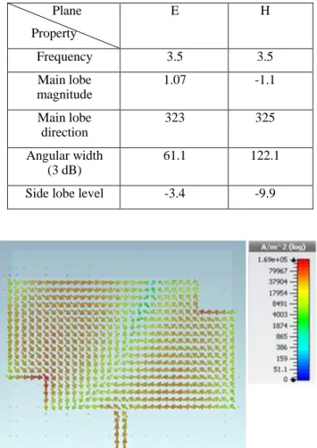
To further study the property of the proposed antenna, we also simulate the surface current distribution for the highest resonant frequency at 3.5 GHz (Fig. 7).
As expected, in the same figure, the strong resonant current flows along the patch surface. More precisely the high density current flows occur at the edge of the conductive layer.
TABLEII. RADIATION CHARACTERISTICPATTERN OF THE PROPOSED ANTENNA AT 3.5GHZ Plane Property E H Frequency 3.5 3.5 Main lobe magnitude 1.07 -1.1 Main lobe direction 323 325 Angular width (3 dB) 61.1 122.1
Side lobe level -3.4 -9.9
Fig. 7. Surface current distribution of the WiMAX antenna at 3.5GHz.
V. CONCLUSIONS
In this work, a flexible and optically transparent purely textile patch antenna for wireless communications was studied with the purpose of being integrated into OLED devices, as well as light sources or flexible displays. This way, the same device is equipped with both lighting and communications functions. The substrate uses micro-strip line for Wireless communication systems WiMAX operating at 3.5 GHz. We have shown that antenna design techniques perform well even for textile substrates and conductive textiles consisting of transparent conductive fabric integrated with polyester. The antenna exhibits omnidirectional radiation coverage with a gain of 1.07 dB at 3.5 GHz for E-Plane polarization (TABLE II). The only drawback is a decrease of the gain at higher frequencies as the dominant losses of the conductive fabric increase with frequency [14].
ACKNOLEDGMENT
This research is part of the PHC “Maghreb” (Programme Hubert Curien) MELINA (Mastering Efficient Lighting In North Africa) and benefits from the financial support of the French Ministry of Europe and Foreign Affairs and Moroccan Ministry of Higher Education and Scientific Research.
The authors would like to thank their colleague Pascal Dupuis from University Paul Sabatier, Toulouse, France, for proofreading this document and making valuable suggestions.
REFERENCES
[1] ZOU, Shi-Jie, SHEN, Yang, XIE, Fengming, et al. Recent Advances in Organic Light-Emitting Diodes: Toward Smart Lighting and Displays. Materials Chemistry Frontiers, 2020, doi: 10.1039/C9QM00716D.
[2] B.d'Andrade, S. Forest. Novel Smart Windows Based on Transparent Phosphorescent OLEDs. United States: N. p., 2006. Web. doi:10.2172/912695.
[3] L. Canale, « Imaginons l’éclairage du Futur », Dossier Mieux Voir Et
Bien-Etre, Magazine LUX, La revue de l’éclairage, n°300, p 45,
janvier-février 2019.
[4] R. Abramo, R. Adams, F. V. Canez, H. Pace and P. Haglind, "Fabrication and testing of the COMWIN vest antenna," MILCOM 2000 Proceedings. 21st Century Military Communications. Architectures and Technologies for Information Superiority (Cat. No.00CH37155), Los Angeles, CA, 2000, pp. 595-598 vol.2. [5] P. Salonen, Y. Rahmat-Samii, H. Hurme and M. Kivikoski, "Effect of
conductive material on wearable antenna performance: a case study of WLAN antennas," IEEE Antennas and Propagation Society Symposium, 2004., Monterey, CA, USA, 2004, pp. 455-458 Vol.1. [6] R. Cicchetti, E. Miozzi, O. Testa, Wideband and UWB antennas for
wireless applications: A comprehensive review. International Journal of Antennas and Propagation, 2017, vol. 2017.
[7] B. Hu, G. Gao, L. He, X. Cong and J. Zhao, "Bending and On-Arm Effects on a Wearable Antenna for 2.45 GHz Body Area Network," in IEEE Antennas and Wireless Propagation Letters, vol. 15, pp. 378-381, 2016.
[8] S. Ha and C. W. Jung, "Reconfigurable Beam Steering Using a Microstrip Patch Antenna With a U-Slot for Wearable Fabric Applications," in IEEE Antennas and Wireless Propagation Letters, vol. 10, pp. 1228-1231, 2011.
[9] L. Yang, A. Rida, R. Vyas and M. M. Tentzeris, "RFID Tag and RF Structures on a Paper Substrate Using Inkjet-Printing Technology," in IEEE Transactions on Microwave Theory and Techniques, vol. 55, no. 12, pp. 2894-2901, Dec. 2007.
[10] S. Zhang, A. Chauraya, W. Whittow, et al., "Embroidered wearable antennas using conductive threads with different stitch spacings,"2012 Loughborough Antennas & Propagation Conference (LAPC), Loughborough, 2012, pp. 1-4.
[11] J. Hautcoeur, X. Castel, F. Colombel,et al.Transparency and electrical properties of meshed metal films. Thin Solid Films, 2011, vol. 519, no 11, p. 3851-3858.
[12] H. A. Elmobarak Elobaid, S. K. Abdul Rahim, M. Himdi, X. Castel and M. Abedian Kasgari, "A Transparent and Flexible Polymer-Fabric Tissue UWB Antenna for Future Wireless Networks," in IEEE Antennas and Wireless Propagation Let., vol. 16, pp. 1333-1336, 2017.
[13] S. Martín Rey, F. Romana Melodia, Mechanical strength parameters on polyester fabrics. Treatment applied in support of large canvas painting:" the expulsion of the merchants from the temple" by artist Saverio Lillo.(1734-1796).Arché, 2010, no 4-5, p. 139-146.
[14] Z. Xu, T. Kaufmann and C. Fumeaux, "Wearable Textile Shielded Stripline for Broadband Operation," in IEEE Microwave and Wireless Components Letters, vol. 24, no. 8, pp. 566-568, Aug. 2014.