Active Shapes:
Introducing guidelines for designing kinetic architectural structures
ByDina E. El-Zanfaly MAS
Master of Science in Architecture
Architecture Department, Faculty of Engineering
Alexandria University, 2009 Bachelor of Science in Architecture Architecture Department, Faculty of Engineering
Alexandria University, 2006
SUBMITTED TO THE DEPARTMENT OF ARCHITECTURE IN PARTIAL FULFILLMENT OF THE REQUIREMENTS FOR THE DEGREE OF
MASTER OF SCIENCE IN ARCHITECTURE STUDIES
AT THE
MASSACHUSETTS INSTITUTE OF TECHNOLOGY JUNE 2011
@ 2011 Dina E. EI-Zanfaly. All Rights Reserved
SACHUSETTS INSTITUTE
OF TECHNOLOGY
JUN 10 2011
LIBRARIES
ARCHIVES
The author hereby grants to MIT permission to reproduce and to distribute publicly paper and electronic copies of this thesis document in whole or in part in any medium now
imnwi~n nr harionftor nrootori
Signature of Author:. 4C Certified by:... Accepted by:... Dina EI-Zanfaly Department of Architecture May 2 0th 2011 '7X Terry Knight Professor of Design and Computation Thesis Advisor
Takehiko Nagakura Associate Professor of Design and Computation, Chair of the Department Committee on Graduate Students
Thesis Advisor: Terry Knight, PhD Professor of Design and Computation, M.I.T Thesis Reader: George Stiny, PhD Professor of Design and Computation, M.I.T
Active Shapes:
Introducing guidelines for designing kinetic architectural
structures
By
Dina E. EI-Zanfaly
Submitted to the Department of Architecture on May 20, 2011 in Partial Fulfillment of the Requirements for the Degree of Master of Science in
Architecture Studies
This thesis proposes guidelines for designing kinetic architectural structures, in
which rules based on shape grammars, are used for motion capturing and design. There is an increasing demand for adaptive architecture that reconfigures itself physically to meet functional or climatic changes. These guidelines provide a way for the architect to describe and design novel kinetic structures based on s/he already has to meet required physical reconfigurations in these structures. Based
on Shape Grammars, the rule A -> t(A) is introduced as a design guideline for
designing kinetic architectural structures. (A) means here an Active Shape, that is a physical shape with motion observed or created by the designer. The Active Shape (A) could be composed from one physical component or several physical components together. t(A) means a new Active Shape produced by applying one or more transformations t on the original Active Shape to produce a novel motion. These transformations could be (1) a transformation of the arrangement of the components of the Active Shape, (2) a transformation of the motion control means between the components of the Active Shape, such as actuators, hinges and linkages, (3) a transformation of the geometry of the components of the Active Shape and any other applicable transformations such as a transformation in the materiality of the components of Active Shape (A). In order to test the above-mentioned guidelines; two design experiments were set up, (1) a workshop with a group of students and (2) a self-study. The workshop consisted of four stages: two design stages and two reporting stages after each design stage. The participants were provided with samples of Active Shapes (A), and they were asked n the first stage to choose one active shape with two arrangements of its components, and design with this active shape a kinetic structure. After reporting what he designed, each participant was then asked to take a kinetic structure from the other participants and apply a transformation on the active shape of this structure, and then report what s/he has done. The self-study consisted of 2 projects designed by the author.
Thesis Supervisor: Terry Knight
Title: Professor of Design and Computation
Thesis Reader: George Stiny
Acknowledgments
First of all, I would like to express my gratitude to the members of my thesis committee for all their help and support throughout this period. Many thanks to my thesis advisor Terry Knight for helping me to develop and deliver my ideas. I really appreciate her patience and support while working on delivering my thesis. I am also grateful to my thesis reader, George Stiny for his feedback and comments.
I would also like to thank Thanos Economou for the stimulating discussions and the useful comments he made on my work. I would also like to thank my colleagues in the Design and Computation Group. I am really grateful to two friends in particular.
Daniel Rosenberg, for his feedback, encouragement and help. Kaustuv DeBiswas for his discussions, feedback and the questions he always asked. I would also like to thank the students who participated in the workshop, Sarah Hovsepian, Carl
Richard Lostritto and Song-Ching Tai.
I would like to thanks the Fulbright commission in Egypt, who made it possible for me to come to MIT.
Finally, I also grateful for my family, for their support and help all the way. I would like to thank my dad Ezz El-Din EI-Zanfaly, and my sister Passent EI-Zanfaly. I dedicate this thesis to my mother, Maha EI-Fakhrany, and my aunt Sanaa El-Zanfaly may their souls rest in peace, I wouldn't have been here without their help and support.
Index 1 Introduction 11 2 Kinetic architecture 13 2.1 Background 13 2.1.1 Definition 13 2.1.2 History 13 2.1.3 Typologies 16
2.1.4 Examples of kinetic architecture 17
2.2 Kinetic architectural design 21
2.2.1 Precedents 21 2.2.2 Design guidelines 24 3 Active Shapes 26 3.1 Rules 26 3.2 Active Shapes 27 3.2.1 Definition 27
3.2.2 The active rules 28
3.2.3 Arrangement 28 3.2.4 Control means 29 3.2.5 Geometry 30 3.3 Motions 30 3.3.1 Rotation 31 3.3.2 Translation 32
3.3.3 Rotation and translation 32
3.4 Workshop 34 3.4.1 The participants 34 3.4.2 The Process 34 3.4.3 Problem 1 36 3.4.4 Problem 2 41 3.4.5 Problem 3 45 3.4.6 Problem 4 48 3.4.7 Problem 5 49 3.4.8 Discussion 51 3.5 A self-study 53 3.5.1 First project 53 3.5.2 Second project 59 3.5.3 Discussion 65
4 Conclusion and future work 67
Bibliography Figure Refrences
1
Introduction
"Charles Darwin has suggested that the problem of survival always depends upon the capability of an object to adapt in a changing environment. This theory holds true for architecture. " (Zuk and Clark
1970)
We are living now in a world in which objects and structures need to move and transform to adapt to various contextual, functional and environmental changes. There is an increasing demand for adaptive architecture that reconfigures itself physically to meet functional or climatic changes. Kinetic architectural structures
have appeared by the first third of the 20th century. A proposed design for a
revolving house by Pier Nervi in 1934 was one of the early designs for kinetic architectural structures, and ever since designers and architects have been
designing and constructing buildings with motion. These structures in motion could be solar louvers, moving spaces and rooms, sunshades, elevators, kinetic facades, or moving roofs.
It's always hard for the designer to figure out how his structure during the design phase will move/fold/ reconfigure into another shape. What Kind of motion should s/he use? Where should s/he begin? The question here is: How can we create and describe novel Behaviors of motion? How to create a moving unit? How can the designer predict certain motion behavior?
There have been some precedents on how to design kinetic architectural structures, but they all just presented the types of motions and elements used in these structures only. Even after looking at these precedents for designing, there aren't any guidelines or frameworks to help the designer to design novel kinetic architectural structures. In addition to that, these physical changes are always described in a discrete way as a change from one state to another without considering the what's really happening between the 2 states to make that change. Simon states that designers start from something and nobody starts from scratch, and designers use precedents "existing situations" and edit them to get their own design "the preferred one", this also applies on designing kinetic architectural structures (Simon 1996). The question here is: what should the designer do, when he looks at a moving structure, and gets inspired by it to change it, add to it, and use it in his own kinetic structure?
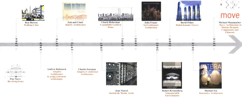
This Thesis proposes guidelines for designing kinetic architectural structures, in which rules based on shape grammars, are used for motion capturing and design. The thesis consists of four chapters; the first Chapter is Introduction. The second chapter is kinetic architecture; this chapter gives a background on kinetic architecture, defines what kinetic architectural structures are, and gives a historical background about kinetic architectural structures, and it shows a historical timeline of the major projects and books about kinetic architecture made by the author. In addition to that, it presents the typologies of kinetic architectural structures by
different authors and designers. For example, some of these typologies for example are categorized according to type of the used motion, which part of the structure is kinetic. This chapter also includes examples of already built kinetic architectural structures. The examples include the Arab league institute by Jean Nouvel, Milwaukee Art Museum by Santiago Calatrava, and the Dubai dynamic towers by Robert Fisher. The chapter also presents the kinetic architecture design
and its precedents in practice and pedagogy, and it ends with asking, " How can
designers design novel kinetic architecture structures?
The third chapter: Active Shapes, and it consists of three parts. It introduces an answer to the question from chapter two by proposing guidelines for designing kinetic architectural structures, in which rules based on shape grammars, are used for motion capturing and design. It starts first by giving a brief background about rules and Shape Grammars, then the term Active Shapes (A) is introduced, which is a physical shape with motion observed or created by the designer. Based on Shape Grammars, the active rule A -> t(A) is introduced as design guidelines for designing kinetic architectural structures. Three basic types of motion are studied in the lights of the new introduced active rules. These basic motions are rotation, translation, and both rotation and translation together. The second part of the chapter documents a workshop organized by the author to test the ideas proposed in the first part. In the third part, the author also studies the ideas by conducting a self-study, which includes two different projects.
The fourth chapter is conclusion and future work reflecting on what has been done and what should the next steps be.
2 Kinetic architecture
This chapter gives a background on kinetic architecture, defines what kinetic architectural structures are, and gives a historical background about kinetic architectural structures, and it shows a historical timeline of the major projects and books about kinetic architecture made by the author. In addition to that, it presents the typologies of kinetic architectural structures by different authors and designers. For example, some of these typologies for example are categorized according to type of the used motion, which part of the structure is kinetic. This chapter also includes examples of already built kinetic architectural structures. The examples include the Arab league institute by Jean Nouvel, Milwaukee Art Museum by Santiago Calatrava, and the Dubai dynamic towers by Robert Fisher. The chapter also presents the kinetic architecture design and its precedents in practice and pedagogy, and it ends with asking, " How can designers design novel kinetic architecture structures?
2.1 Background
2.1.1 Definition
Willian Zuk and Roger Clark defined kinetic architecture as "the architectural form could be inherently being displaceable, deformable, expandable or capable of
kinetic movement". They described the implication of kinetic architecture by describing design by becoming a "continuous process", which "will not stop when the building is erected" (Zuk and Clark 1970).
One of the simplest definitions is Robert Kronenberg's, where he defined kinetic architecture as "Buildings or building components with variable mobility, location, and/or geometry." (Kronenberg, Lim and Chii 2003)
In his book Interactive Architecture, Michael Fox describes it "as either transformable objects with dynamically occupy predefined physical space, or moving physical objects that can share a common physical space to create adaptable spatial configurations." (Fox and Kemp, Interactive Architecture 2009)
2.1.2 History
Kinetic structures are not new; in the late 1400's Leonardo Da Vinci designed several kinetic structures, he designed a crane that can move and carry heavy things (M. Asefi 2010). Kinetic architectural structures have appeared by the first
third of the 2 0th century. One of the early kinetic architectural structures is a
proposed design for a revolving house by Pier Nervi in 1934; in the 1960's Richard Forster built a similar structure (Figure 1). The General Electric Pavilion is also a good example, it was built in the 1964 World's Fair was designed by Welton
Becket's architecture firm (Zuk and Clark 1970). (Nouvel 2008). Figure 2 shows a timeline for the major historical kinetic structure projects and books in the 2 0 h
century, including Heroons's walking City in the 60's and ending with Michael Schumacher's book "Move: Architecture in Motion- Dynamic Components and Elements" in 2010.
Figure 1: Two revolving residences, The left one is a proposed design by Pier Nervi 1934 and the right is built in the 60's in Connecticut by Richard Foster.
. .... ... .. ... .... .. I .. .. ... .... ... .. .. .. .. ....
David Fisher
Dubtai dnamic TImers
0% C C
move
Michael Shaumacher \os : \rchitecturce in \lotion: ) Nnail oponents and I lemtust CKo tt! nironennerg rmnaCnalC rox I ranpoiriable liIraei krchilctur
Lnvironmentt
Figure 2: A timeline for the major historical kinetic structure projects and books in the 2 0th century
/uk and Clark
Kinetic %rchitecturr (huck luberman Ssiandable Cedic Iome C AI. E litionars, Architecture CIS Charles Eastmas \daptised( onditionaI \rchifecture Pier Nervi
Re0,a ing house
Andrew Raheneck %daplise %rchitecturc bi using c hectit lechnologie% Jcan Nouvel
lastitel dit Nionde \rabe "0
Ch Ron Herron
42lkn
2.1.3 Typologies
In their book kinetic architecture, William Zuk and Roger Clark divided Kinetic architecture into eight classes or " Kinetiscism" in which some of these categories can coexist together. The authors describe the first four classes as "closed system kinetics", in which the " design decisions for future changes must be made prior to the erection of the original form". Those four classes are: (1) Kinetically controlled static structures, (2) Dynamically self-erecting structures, (3) Kinetic component and (4) Reversible architecture. On the other hand, (5) Incremental architecture can be opened to "accept new, outside elements which may not have existed at the time of the formal inception." (Zuk and Clark 1970)
Michael Fox classified kinetic systems in architecture to 3 typologies: (1) Embedded, (2) Deployable, and (3) Dynamic kinetic structures. Embedded Kinetic structures are systems that "exist within a larger architectural whole in a fixed location" and they are used to "control larger architectural system or building. They are used to control the larger architectural system or building, in response to changing factors". Those Changes are may be caused by both "environmental and human factors" and may include" axial, torsion, flexural, instability and vibration and sound." Deployable Kinetic Structures: Deployable Kinetic structures typically exist in a temporary location and are easily transportable. Such systems possess the" inherent capability to be constructed and deconstructed". Applications may include "traveling exhibits, pavilions and self-assembling shelters in disaster areas.
" Dynamic Kinetic Structures: Dynamic systems "act independently with respect to the architectural whole. " Applications may include "louvers, doors, partitions, ceilings, walls and various modular components." (Fox and Kemp, Interactive Architecture 2009)
Maziar Asefi introduced there types of transformable/kinetic structures (Figure 3);
(1) Transformable tensile structures, which consist from transformable tensile
membranes and transformable compressive- tensile architectural structures. (2) Transformable bending and compression structures, which consists from spatial bar structures and spatial frame structures (M. Asefi 2010).
In his book Move: Architecture in motion- dynamic components and elements, Michael Schumacher classified kinetic architectural structures to motion types of buildings and building elements: (1) Swivel, (2) Rotate, (3) Flap, (4) Slide, (5) Fold,
(6) Expand, (7) Gather and roll up and (8) pneumatic. (Schumacher, Schaffer and
Vogt 2010)
Integrated
Figure 3: Classification of transformable Architectural structures according to Maziar Asefi
2.1.4 Examples of kinetic architecture
In this section, some important examples for kinetic architectural structures are introduced to highlight the importance of kinetic architecture, and why it is important to have guidelines for designing kinetic architectural structures. The examples included kinetic parts of a building like the facades, louvers and a kinetic ceiling. The examples also included, fully kinetic structure, tensile structure, and fully revolving towers.
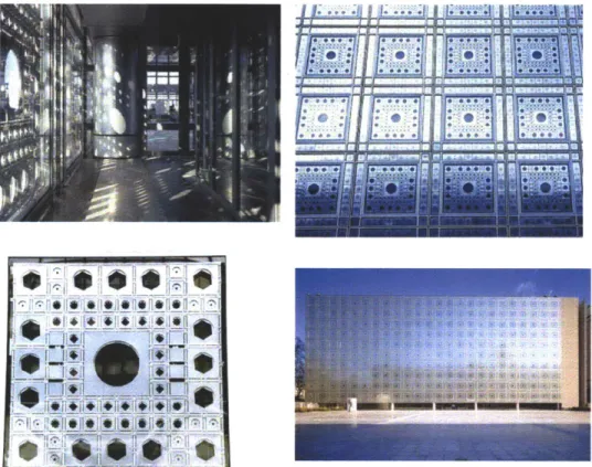
A. Arab World Institute by Jean Nouvel, Paris
"Geometry and light ....how a fagade facing the sun may program its
interior spaces through its perforations and shadows...." (Nouvel
2008)
This building is a major kinetic architectural project that was built in the 1980's in Paris by Jean Novel. The institute features "radical high-tech walls emblazoned with mechanical apertures that respond to sunlight by narrowing to reduce solar exposure or dilating to allow daylight to suffuse the interior." (Archietcture view 2010)
* *
lii1
Amok,# r,Figure 4: Arab World Institute by Jean Nouvel, Paris
B. Milwaukee Art Museum by Santiago Calatrava, Milwaukee, USA
Inspired from nature, Santiago Calatrava designed in 2001 the museum with a moveable "wing-like sun screen" atop of the museum itself. "The 115 ton steel brise soleil consists of two equal wing elements formed by 36 fins whose lengths range between 8 and 32 meters. The vaulted, steel and glass structure has become the signature element of the Wuadracci Pavilion and a symbol to the city" (Calatrava 2001).
Figure 5: Different states of the museum's brise soleil.
.
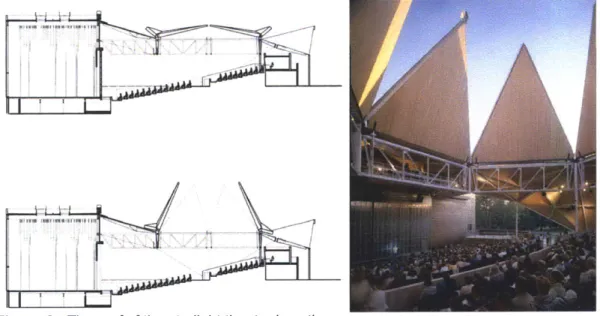
-C. Starlight theatre by Studio Gang Architects, Rockford, il
The central theatre space forms an unexpected vertical axis to the sky; an observatory to the stars through a kinetic roof that opens in fair weather. The faceted roof structure was built out of wood and steel in 2003. The kinetic center sections open upward like "the petals of a flower in a helical order so that each roof petal overlap its neighbor." (P. 2009)
Figure 6: The roof of the starlight theatre in action.
D. Expanding Geodesic Dome by Chuck Hoberman, New Jersey, USA The Expanding Geodesic Dome transforms and "open from a 1.5-meter cluster to a 6-meter structural dome when pulled open from its base. When deployed it has the same shape and triangulated pattern as Buckminster Fuller's static, geodesic dome, taking this seminal historic structure into the 21st century." (Hoberman, Expanding Geodesic Dome 2011)
Figure 7: Expanding Geodesic Dome by Chuck Hoberman, 1991.
E. The Medina umbrellas by Bodo Rasch, KSA The Medina umbrellas by Bodo
courtyard for morning prayers.
Rasch, they unfold at sunrise to shade the
K
t: i ne umoreiias in acuon covering tne courtyara.
F. Dubai dynamic tower by Robert Fisher, Dubai, UAE
This is the world's first prefabricated skyscraper, each floor will be able to rotate independently, which will result in a constantly changing shape of the tower. Each floor will rotate a maximum of 20 ft per minute, or one full rotation in 90 minutes.
Figure 9: The Dubai rotating tower.
2.2 Kinetic architectural design 2.2.1 Precedents
In their book, Kinetic Architecture, William Zuk and Clark presented some students' work for kinetic architecture projects in design studios at the university of Virginia. But they haven't explained their pedagogical approach or the design process for these kinetic structure projects (Zuk and Clark 1970).
Figure 10: The folding decahedron which self-erects was developed as a student project
by James Pettit and John Cox at the university of Virginia.
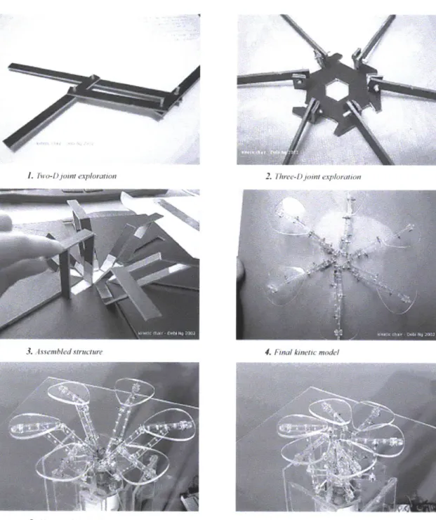
In "Starting From The Micro: A Pedagogical Approach to designing interactive Architecture" Michael Fox and Catherine Hu introduced a pedagogical approach for creating responsive architecture systems. They introduced cumulated discrete explorations, which can be quickly learned to produce full-scale interactive architectural environments. The paper explored several aspects for creating a responsive environment including human and environmental interaction and behaviors, embedded computational infrastructures, kinetic and mechanical systems and physical control mechanisms (Fox and Hu 2005). They used different design approach from typical design courses, a micro approach instead of a macro. So instead of starting by finding the problem, then research and then design, they started by designing the mechanical structures first, then "grow" the system by adding sensors and motors.
"Basic engineering concepts in mechanical structures were also introduced. Simultaneously, students were asked to explore various mechanical motions and joints from found objects and structures that intrigued them, and then select one structure to examine closely its underlying mechanics. They were then required to build and re-model the mechanical structure to replicate and expand its basic kinetic capabilities." (Fox and Hu 2005)
... :
2. T1hre-D joint exploration
3. Assembled structure 4. Final kinetic model
5. ( Char nodule half-rse, n) 6. aible module (fully raised)
Figure 11: Design Example from the studio: Kinetic Chair/Table Systems.
"This interactive design project for kinetic chair/ table systems demonstrates the simplified prototypical kinetic attributes that first grew from a simple exercise in mechanical design. The simple mechanical model of cardboard that demonstrated the motion grew to a precise mechanism with gears and motors and sensors." (Fox and Hu 2005)
-- --- --- -- ... .........
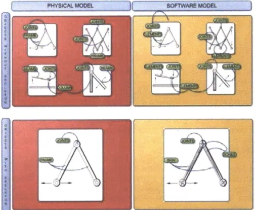
In 2007, Angeliki Fotadou wrote a thesis about Analysis of design Support for kinetic structures. In her thesis she attempted to forma and systemize a basis of knowledge and information, which is indispensable to turn a design support for kinetic structures into representation by means of a 3d animating program. She studied modeling kinetic structures in softwares and evaluating them through case studies. The evaluation criteria for the softwares are: (1) Possibility of creating proportional design, (2) Modification of Spatial arrangement, (3) possibility of creating parametric elements, (4) Elements, objects definition, (5) joints definition,
(6) control time function, (7) Existence of scripting language and (8) types of
import/export files (Fotiadou 2007).
if SOIWAEMODL
Figure 12: Angeliki Fotadou's comparison between mechanical model and a model implemented into animation software.
In his book, transformable and kinetic structures, Masiar Asefi states that it is difficult to select and design "proper transformable structural system that mostly suits the design requirements." In order to evaluate the best solution "from a number of exiting alternative," "design criteria" should be put into consideration. So he presented design guidelines to help architects through the selection process of transformable structures. He grouped the criteria in 4 categories (1) Design, which covers Expansion and flexibility, compactability and transportability, structural stability and deformability, Architectural obstruction and Operating system. (2) Construction and Operation which includes Reliability and Safety, Auxiliary equipment and manufacture and shipment. (3) Maintenance and costs, which includes Life expectancy, maintenance management strategies, Capital cost, Running and maintenance costs. (4) Application by defining the scale of the application (small-scale, medium-scale or Large-scale) (M. Asefi 2010).
... ... ...
In "Move: Dynamic components and elements in architecture", the authors addressed the technical and design problems of kinetic structures faced by designer and builders. They tried to investigate how dynamic movements in buildings could be "illustrated, accommodated, and controlled." The Authors presented in this book the technical tools and constructional solutions that will allow the designers and builders to implement movements in buildings concretely and deploy them functionally within the domains of ""Energy,"" ""Change of Use,"" and ""Interaction." (Schumacher, Schaffer and Vogt 2010).
2.2.2 Design guidelines
Even after looking at the above-mentioned precedents for designing kinetic architectural structures, there aren't any guidelines or frameworks to help the designer to design novel kinetic architectural structures. Simon states that designers start from something and nobody starts from scratch, and designers use precedents "existing situations" and edit them to get their own design "the preferred one" (Simon 1996), this also applies on designing kinetic architectural structures. The question here is: what should the designer do, when he looks at a moving structure and gets inspired by it to change it and add to it, and use it in his own kinetic structure?
This Thesis proposes guidelines for designing kinetic architectural structures, in which rules based on shape grammars, are used for motion capturing and design. As Simon states that designers start from something and nobody starts from scratch (Simon 1996), this also applies on designing kinetic architectural structures. The question here is: what should the designer do, when he looks at a moving structure, and gets inspired by it to change it, add to it, and use it in his own kinetic structure?
3 Active Shapes
This chapter consists of three parts. It introduces an answer to the question from chapter two by proposing guidelines for designing kinetic architectural structures, in which rules based on shape grammars, are used for motion capturing and design. It starts first by giving a brief background about rules and Shape Grammars, then the term Active Shapes (A) is introduced, which is a physical shape with motion observed or created by the designer. Based on Shape Grammars, the active rule A
-> t(A) is introduced as design guidelines for designing kinetic architectural
structures. Three basic types of motion are studied in the lights of the new introduced active rules. These basic motions are rotation, translation, and both rotation and translation together. The second part of the chapter documents a workshop conducted by the author to test the ideas proposed in the first part. In the third part, the author also studies the ideas by conducting a self-study, which includes two different projects.
3.1 Rules
"Shape Grammars were one of the earliest algorithmic systems for creating and understanding designs directly through computations with shapes, rather than indirectly through computations with text or symbols" (Knight 2000)
George Stiny and James Gibs introduced Shape Grammars in 1972 as a new visual approach to design and analysis (Stiny and Gips 1972). These computations on shapes are performed in 2 steps; first recognizing a particular shape, and second applying a rule that specifies which shape could be replaced, and how it could be replaced. The rule consisted of 2 shapes separated by one arrow, in which the shape on the right side is replaced by the shape on the left side by applying transformation operations with in the rule.
rule: initial shape
computation:
Figure 13: Rules for a triangle as an initial shape and its computation.
3.2 Active Shapes 3.2.1 Definition
The term Active Shape here is introduced where Active shape (A) is a physical shape with motion observed or created by the designer. The Active shape (A) could be composed from one physical component or several physical components together. There has been a term introduced by Tim Cootes and Chris Taylor in
1995, Active shape models (ASMs), and this term has been defined as "statistical
models of the shape of objects which iteratively deform to fit to an example of the object in a new image" (Cootes n.d.). Active shape models are not related to kinetic architectural design or structures but rather they are used for locating bones and organs in medical images. The term Active Shape, introduced here in this thesis, is used to describe physical shapes in motion in kinetic structures.
Figure 14: Just a Physical shape without any kind of motion.
A
Active Shape A is a Physical Shape with Motion.
Figure 15: Active Shape A is a Physical Shape with Motion.
... .
3.2.2 The active rules
This Thesis proposes design guidelines for kinetic architectural structures in which rules based on shape grammars, are used for motion capturing and design. Based on Shape Grammars, the rule A -> t(A) is introduced as design guidelines for designing kinetic architectural structures. (A) means here Active shapes, in which Active shape (A) is a physical shape with motion observed or created by the designer. t(A) means a new Active Shape produced by applying one or more transformations t on the original Active Shape to produce a novel motion. These transformations could be (1) a transformation of the arrangement of the parts of the Active Shape, (2) a transformation of the motion control means between the parts
of the Active Shape, such as actuators, of the geometry of the parts of the transformation such as a transformation
A
Active Shape A is a Physical Shape with Motion.
hinges and linkages, (3) a transformation Active Shape or it can be any other in the materiality of the Active Shape.
->
t(A)
t(A) is a new Active
Shape produced by the transformation t applied on the original Active Shape A.
3.2.3 Arrangement
The first transformation in the above mentioned rule could be a transformation in the arrangement of the components of the Active Shape. In the mentioned example here, a scissor pair mechanism with a central pivot point is considered as Active Shape (A). By applying a transformation in arrangement on the Active
Shape (A), the pivot point of the scissor pair structure is shifted above the center point, which results in t(A), a new Active Shape with a new motion.
A
t(A)
Figure 16: The rule showing the original Active Shape A and once the transformation in arrangement t is applied on it, it becomes a new active shape t(A).
3.2.4 Control means
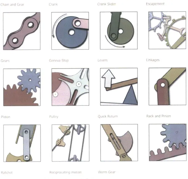
The second transformation in the above mentioned rule could be a transformation in the control means between the components of the Active Shape. Control means include sliders, gears, pneumatics, actuators, hinges and linkages.
(Id Slh Fscap
x-w
Rack and Pinior
Figure 17: Some examples for motion controllers.
In the mentioned example here, a scissor pair mechanism with one central pivot point is considered as Active Shape (A), it has a rotational motion around one point. By applying a transformation in the control means of the components of the Active Shape (A), the pivot point of the scissor pair structure is replaced by a
sliding controller, which results in t(A), a new Active Shape with a new motion and new degrees of freedom.
... ... 11 ... ... - ... ... ... ... ... .. .. - " - ':: -- Y ". ': I ", 11 :::::: - .. ; .. : 11 % % -, % I vl . - -" . I
A
t(A)
-U)
Figure 18: The rule showing the original Active Shape A and once the transformation in control means t is applied on it, it becomes a new active shape t(A).
3.2.5 Geometry
The second transformation in the above mentioned rule could be a transformation in the geometry of the components of the Active Shape. In the mentioned example here, a scissor pair mechanism with one central pivot point is considered as Active Shape (A), it has a rotational motion around one point. By applying a transformation in the geometry of the components of the Active Shape (A), the straight components are replaced by a curved components, which results in t(A), a new Active Shape with a new motion.
A
t(A)
Figure 19: The rule showing the original Active Shape A and once the transformation in geometry t is applied on it, it becomes a new active shape t(A).
3.3 Motions
In order to test the above-mentioned transformations, 3 basic types of motions are studied. The studied basic motions are: (1) Rotation, (2) translation and (3) Rotation and translation.
3.3.1 Rotation
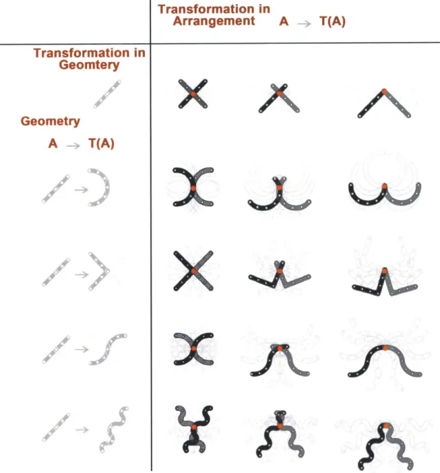
One pivot point as a control mean is used to create a rotational motion from components of the Active Shape (A). In order to create a matrix between transformation in arrangement t, the transformation in control means t and transformation in the geometry of the components t of the Active Shape (A), control mean stays the same in this table, and the change is between transformation in geometry t and transformation in arrangement t of components of the Active Shape (A).
Transformation in
Geomtery
Geometry
A
-T(A)
NTransformation in
Arrangement
x
x
x
x
w
A
T(A)
%A
Figure 20: A table showing the change in the transformations in Geometry t of the components of the Active Shape (A) with respect to the tranfromations in the arrangment t of the componenets of the active shape (A). The control mean stays the same in all the transformations in this table.
the the the the the the
%~AJ
... .. .. ... ... ... ... ...3.3.2 Translation
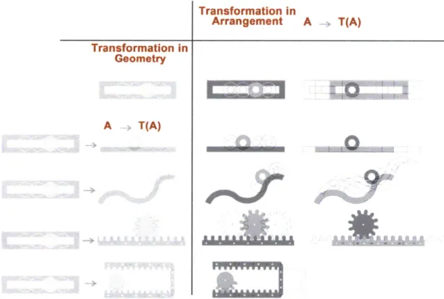
A slider is used as a control mean to create a translational motion from the
components of the Active Shape (A). In order to create a matrix between the transformation in arrangement t, the transformation in control means t and the transformation in the geometry of the components t of the Active Shape (A), the control mean stays the same in this table, and the change is between the transformation in geometry t and transformation in arrangement t of the components of the Active Shape (A). All Active Shapes (A) in the table have the same motion (translation), they have the same control mean, but they vary as a transformation t in the arrangement or the geometry of their components occurs.
Transformation in
Arrangement A T(A)
Transformation in Geometry
A T(A)
Figure 21: All Active Shapes (A) in the table have the same motion (translation), they have the same control mean, but they vary as a transformation t in the arrangement or the geometry of their components occurs.
3.3.3 Rotation and translation
A pivot point and a slider are used together as control means to create a rotational
motion from the components of the Active Shape (A). In order to create a matrix between the transformation in arrangement t, the transformation in control means t and the transformation in the geometry of the components t of the Active Shape
(A), the control mean stays the same in this table, and the change is between the
transformation in geometry t and transformation in arrangement t of the components of the Active Shape (A). All Active Shapes (A) in the table have the
same motion (rotation and translation), they have the same control mean, but they vary as a transformation t in the arrangement or the geometry of their components occurs. Transformation in
Geometry
A
>
T(A)
Transformation in
Arrangement
A
T(A)
X
Figure 22: All Active Shapes (A) translation), they have transformation t in the occurs.
in the table have the same motion (rotation and the same control mean, but they vary as a arrangement or the geometry of their components
3.4 Workshop
In order to test the above-mentioned guidelines for designing kinetic architecture structures; I decided to set up a design experiment such as a workshop with a group of students at the design and computation group at Massachusetts Institute of Technology.
3.4.1 The participants
- Six students volunteered to participate in the workshop. They are:
- Sarah Hovsepian, first year student in Master of Science in Architectural
studies (SMArchS), Design and Computation (Student A).
- Carl Richard Lostritto, first year student in Master of Science in
Architectural studies (SMArchS), Design and Computation (Student B).
- Song-Ching Tai, first year student in Master of Science in
studies (SMArchS), Design and Computation (Student C). SDina EI-Zanfaly, second year student in Master of Science in
studies (SMArchS), Design and Computation (Student D). Daniel Rosenberg, second year in PhD in Design and (Student E).
- Kaustuv Kanti De Biswas, final year in PhD in Design and
(Student F). Architectural Architectural Computation Computation 3.4.2 The Process
The experiment consisted of four stages: two design stages and two reporting stages after each design stage. In the first design stage the participants were provided with physical above-mentioned tables of Active Shapes, and were asked to choose one Active Shape with one or two arrangements. The participants were also allowed to use any representational techniques such as sketching or modeling. After reporting what they have done in the first stage, the participants started a new design stage, they were asked to take a structure from their colleague and apply one of the transformations mentioned above on the Active Shape, from which the original structure consists, and design a kinetic structure. Five problems have been documented, three of them have four stages, and the other two problems went through the first design and reports stages.
Figure 23: Physical table of Active Shapes presented to the participants.
35
3.4.3 Problem I
The participants are students C and E.
First Stage: Creating a kinetic structure from the given tables.
Student C chose one Active Shape (A) with two arrangements.
Transformation in
Arrangement
A
T(A)
Transformation in
Geometry
A
Figure 24: The Active Shape chosen by student C, the student chose one Active Shape
(A) with two arrangements.
Figure 25: The kinetic structre created by student C by using one Active Shape (A) with
two arrangements.
Second Stage: Student C reports the design stage.
He tried at first to create a symmetrical structure, so he fixed all the joints/pivot points at the same place. He expected the structure to act like a scissor or a straight member, but he realized that it behaves a little bit different than he thought, and there is definitely another horizontal motion. He realized that by using the 2 arrangements he is getting a large motion from the structure he created by just using a small motion from the first part of the structure. He started thinking about multiplying the structure, which might result in larger motion in the structure with
smaller created by him at the first member. The student said that he didn't have anything in mind while he was designing it; he was only thinking how to create an efficient deployable structure.
Figure 26: Student C reporting what he did in the first design stage: He realized that by using the 2 arrangements he is getting a large motion from the structure he created by just using a small motion from the first part of the structure.
Third Stage: Applying one of the transformations on the design produced in the first stage by another participant.
Student E applies a transformation in geometry t on the Active Shape (A) chosen by student C in the first stage. He kept the same arrangement from the first stage.
Transformation in
Arrangement
A
-*
T(A)
Transformation in
Geometry
A
A
Figure 28: The Transformation in geometry t made by Student E on the Active Shape (A) chosen by student C in the first stage, the arrangement of the components of the Active shape are kept the same from the First Stage.
4
Figure 29: Opening state: A comparison between the original kinetic structure created by student C from stage one and the new kinetic structure created by student E created in stage 3 by applying a transformation t on the original Active Shape (A) from stage one.
T(A)
x
.. ... ... ... ... ... ...
Figure 30: Closing state: A comparison between the original kinetic structure created by student C from stage one and the new kinetic structure created by student E created in stage 3 by applying a transformation t on the original Active Shape (A) from stage one.
Fourth Stage: Student E reports the design stage, where he applied a
transformation in geometry t on the original active shape (A). The student here used the transformation in geometry as a descriptive method for the original structure. He wanted to see the motion in the original structure. He realized that by keeping the arrangement and changing the geometry of the components, interesting result is produced. The student commented on what he did as a way to describe a motion. He stated that because the components are curved and not on a straight line, it produced an interesting motion.
Figure 31: He realized that by keeping the arrangement and changing the geometry of the components, interesting result is produced.
3.4.4 Problem 2
The participants are students E and A.
First Stage: Creating a kinetic structure from the given tables. Student E chose one Active Shape (A) with two arrangements.
Transformation in
Geometry
ffTransformation in
Arrangement
Ju
Figure 32: The Active Shape chosen by student E, the student chose one Active Shape (A) with two arrangements.
A~' /
-k
/
Figure 33: The Kinetic structre created by student C by Using one Active Shape (A) with two arrangements.
A
-
T(A)
... ... ... . ... ... . ... ... .. ... ... .. ... ... .. ... ...
Figure 34: Stage one- Created by Student E.
Second Stage: Student E reports the design stage. He described the structure as set of circles, but once and it will look like flowers. He described it as a wall windows.
it put in motion, it opens up that opens up with different
3 4
Figure 35: Student E describing his design.
Third Stage: Applying one of the transformations on the design produced in the first stage by another participant.
Student A applies a transformation in geometry t on the Active Shape (A) chosen by student E in the first stage. She kept the same arrangement from the first stage.
Transformation in
Geometry
A
T(A)
Transformation in
Arrangement
Ju
Figure 36: The transformation in geometry t made by Student A on the Active Shape (A) chosen by student E in the first stage, the arrangement of the components of the Active shape are kept the same from the First Stage.
It i
*4
Figure 37: Opening and closing states: A comparison between the original kinetic structure created by student E from stage one and the new kinetic structure created by student A created in stage 3 by applying a transformation in geometry t on the original Active Shape (A) from stage one.
A
-
T(A)
Fourth Stage: Student A reports the design stage, where he applied a
transformation in geometry t on the original active shape (A). She replaced the half circle with a right angle; she described it as a diamond shape. She has added 2 more components than the original shape. She realized that the shapes are not affecting each other and creating the motion as the original
structure. She described them as modules not affecting each other.
3.4.5 Problem 3
The participants are students A and B.
First Stage: Creating a kinetic structure from the given tables. Student A chose one Active Shape (A) with one arrangement.
Transformation in
Transformation in
Geomtery
A
Transformation in
Arrangement
Figure 38: The Active Shape chosen by student A, the student chose with two arrangements.
A
_
T(A)
one Active Shape (A)
Second Stage: The Transformation in geometry t made by Student A on the Active Shape (A) chosen by student E in the first stage, the arrangement of the components of the Active shape are kept the same from the First Stage.
She wanted everything to collapse on itself, to save the space and take the least area initially. She would like to expand it to be a multiple use structure to form a table or a desk to save space.
Third Stage: Applying one of the transformations on the design produced in the first stage by another participant.
Student B applies a transformation in geometry t on the Active Shape (A) chosen by student A in the first stage. He kept the same arrangement from the first stage.
A
T(A)
Figure 39: The Transformation in control mean t made by Student B on the Active Shape (A) chosen by student A in the first stage, the arrangement of the components of the Active shape are kept the same from the First Stage.
Fourth Stage: Student B reports the design stage, where he applied a transformation in the control mean t on the original Active shape
(A) and got a new Active Shape t(A).
He commented that by changing the control mean to a slider, the structure became loose, and now he is more inclined to introduce more constraints systematically by putting more connections.
3.4.6 Problem 4
The participant is student B.
First Stage: Creating a kinetic structure from the given tables.
Student B chose one Active Shape table and the other not from it.
(A) with two arrangements, one from the given
Transformation in
Transformation in
Geometry
A
Transformation in
Arrangement
A
T(A)
TM
I
The Active Shape chosen by student
with two arrangements.
B, the student chose one Active Shape (A)
Second Stage: Student E reports the design stage.
Advantage of the curve, hard time visualizing anymore that 2 pieces connected, can't simulate it in his head, it was a hands on work. He tried to make it asymmetric and continuous.
Figure 40:
3.4.7 Problem 5
The participant is student F.
First Stage: Creating a kinetic structure from the given tables.
Student F chose one Active Shape (A) with two arrangements, but he also choose to
Transformation in
Arrangement
A
~,
T(A)
Transformation in
Geometry
AX
Figure 41: The Active Shape chosen by student B, the student chose one Active Shape (A) with two arrangements and sizes.
Figure 42: Stage one- Created by Student F
Second Stage: Student E reports the design stage.
Figure 43: Student B reporting his model.
3.4.8 Discussion
- Although it is still difficult for the designer to predict the exact behavior of
motion of a kinetic structure in the design process, the workshop has proved that once the designer follow the presented guidelines, he /she gets better idea of what would happen to the motion if he/she applied one or more of the transformations on the components of the Active shape. The trial and error process will be still used to give an idea how a kinetic structure moves, but the introduced guidelines in this thesis proved to be more efficient, and give the designer the ability to produce novel kinetic structures.
- The guidelines also proved that they could be used as descriptive tools as
seen in the third stage in problem one. This would help the designers to look at different kinetic motions and describe them with these tools and get an Active Shape (A). By applying transformation on the Active Shape (A) the designer gets a new Active Shape (A) that could fit to his design problem.
- Without simulation softwares or digital fabrication of the active shapes, it's
very hard to predict the exact motion or quantitate information.
- Assembly of more than an Active Shapes is very important here. As we
seen in one of the examples, the student said that he can't imagine the kinetic motion of the structure, unless with the hands -on exercise.
3.5 A self-study 3.5.1 First project
In this project I started looking at Origami. I studied the Kelidocycle, a connected ring of tetrahedrons, which give specific rotational motion.
Figure 44: Kleidocycle in Action.
By observing the Kleidocycle in action, I chose my Active Shape as two tetrahedrons connected together, and I studied their behavior.
Figure 45:Choosing the active shape from the kleidocycle.
Figure 46: Caption for the movement of the Active Shape.
I chose a transformation in geometry t to be applied on the components of the original active shape, which I got from the kelidocycle.
A
->
t(A)
Active Shape A is a Physical Shape with Motion.
t(A) is a new Active
Shape produced by the transformation t
applied on the original Active Shape A.
Figure 47
... ... ... m m ... ... ...
\\\ 1/
Figure 48: Caption for the new movement of the Active Shape (A) .
Figure 49
After Assembling 3 active shapes together, I got a Kleidocycle in which it
has 2 separate motions. 1. Revolving, and 2. Folding
... , - -... .. .... ... ...
: First type ot motion , same as the normal kleidocycle.
Figure 52: Embedding computation inside the kinetic unit to act as one unit in a shape shifting structure.
Figure 53: One unit in the structure.
F :ls
3.5.2 Second project
I studied the conceptual design and digital fabrication of Scissor-pair Transformable Structures. I created a foldable surface which can be used as a process which includes 2 steps; First, the Conceptual design and the parametric modeling. Second, the digital fabrication process, This Process includes the fabrication and applying the mechanism. Arduino, a microcontroller, and a small motor are used with a sensor to manipulate the structure's motion; this is used to mimic the change in the structure when it reacts to any contextual or environmental change in the reality.
A
->
t(A)
KxXX
Figure 55: Applying a transformation in arrangement on a a radial motion instead of a horizontal one.
scissor par structure, resulting in
S
Figure 56: Diagrams showing the radial motion.
... ... ...
+ ,.~ ,~t'uq
Please check the videos on the website www.dzanfaly.com
Figure 57: using Digital project and digital fabrication for simulation.
I
I
Figure 58: Implementation1: Arcades.
r ~4 1/ * > J~t ~j ~ J~ p 'V
Figure 59: Implementation 2: Amphitheater
Figure 60: Implementation 3: Emergency Housing.
1 . :: ,- ..:::.::::::::::::%:.:: ... ... ... .... .... ... ... r ... ... ... 11 ... . ...
.. .... .... .. ..... .. .
*
P.
Figure 61: Implementation 4: Swimming pool.
64
3.5.3 Discussion
This self-study showed the design process based on the newly introduced guidelines for designing kinetic architectural structures. And how the active rules are applied from the conceptual phase, and the how the structure is developed till the building phase.
4 Conclusion and future work
This research aimed at introducing guidelines for designing novel kinetic architectural structures. The driving force behind this that by looking at the precedents for designing kinetic architectural structures, It is found that there aren't any guidelines or frameworks to help the designer to design novel kinetic architectural structures. Simon states that designers start from something and nobody starts from scratch, and designers use precedents "existing situations" and edit them to get their own design "the preferred one" (Simon 1996), this also applies on designing kinetic architectural structures. The question here is: what should the designer do, when he looks at a moving structure and gets inspired by it to change it and add to it, and use it in his own kinetic structure?
So in this thesis the author tried to find an answer to the following question: "How can designers design novel kinetic architectural structures?"
This Thesis proposed guidelines for designing kinetic architectural structures, in which rules based on shape grammars, are used for motion capturing and design. The term Active Shape here is introduced where Active shape (A) is a physical shape with motion observed or created by the designer. The Active shape (A) could be composed from one physical component or several physical components together. The rule A -> t(A) is introduced as design guidelines for designing kinetic architectural structures. (A) means here Active shapes, in which Active shape (A) is a physical shape with motion observed or created by the designer. t(A) means a new Active Shape produced by applying one or more transformations t on the original Active Shape to produce a novel motion. These transformations could be
(1) a transformation of the arrangement of the parts of the Active Shape, (2) a
transformation of the motion control means between the parts of the Active shape, such as actuators, hinges and linkages, (3) a transformation of the Geometry of the parts of the Active Shape or it can be any other transformation such as a transformation in the materiality of the Active Shape.
In order to test the above-mentioned guidelines for designing kinetic architecture structures; I decided to set up design experiments such as a workshop with a group of students at the design and computation group at Massachusetts Institute of Technology and a self study including two design projects.
The workshop has proved that once the designer follow the presented guidelines, he /she gets better idea of what would happen to the motion if he/she applied one or more of the transformations on the components of the Active shape. The trial and error process will be still used to give an idea how a kinetic structure moves, but the introduced guidelines in this thesis proved to be more efficient, and give the designer the ability to produce novel kinetic structures. It also showed as in problem 2, that the active rules could be used as a descriptive tool to understand and look deeply at another kinetic structure. Which could be used as a pedagogical guide.
The self-study showed how the active rules are applied from the conceptual phase, and the how the structure is developed till the building phase.
There are too many parameters, and too many areas in designing a whole kinetic structure has to be explored and researched. The materiality should be also studied as a major transformation parameter in the active rules. In addition to exploring the rest of the possible transformations in the active rules, the presented guidelines should be put in a framework for designing the kinetic structures, which should also contain: The design mediums, which includes the simulation softwares and physical prototyping. Some of these elements should be also connected in a loop like the virtual design and the physical prototyping to maintain the connection of geometry and physics to materiality, mechanics and scalability. Several stages should be introduced in the framework including: (1) motion types, whether it is continuous or discrete,(2) the motion speed, (3) the degrees of freedom,(4) the material properties and (5) the structure scalability.
Bibliography
Zuk, William, and Roger Clark. Kinetic Architecture. New York: Van Nostrand Reinhold, 1970.
Asefi, Maziar. Transformable and Kinetic Architecural Structures. Breinigsville: VDM Verlag Dr. Mueller, 2010.
Asefi, Mazier, and Robert Kronenburg. "An Architectural Evaluation of
Transformable Roof Structures." International Conference On Adaptable Building Structures. Eindhoven , 2006. 85-90.
Archietcture view. 2010. http://www.architecture-view.com/201
0/10/15/stunning-institut-du-monde-arabe-in-france/ (accessed April 30, 2011).
Architecture.org, interatcive. Some thoughts on Responsive Kinetic Architecture.
August 2006. http://www.interactivearchitecture.org/some-thoughts-on-responsive-kinetic-architecture.html (accessed May 10, 2011).
Beesley, Philip, Hirosue Sachiko, and Jim Ruxton . Responsive Architectures:
Subtle Technologies. Riverside Architectural Press; Ill edition, 2006.
Calatrava, Santiago. Milwauakee Art Museum. 2001.
http://www.calatrava.com/#/Selected%20works/Architecture/Milwaukee?mode=eng lish (accessed May 10, 2011).
Cook, Peter. Archigram. Princeton Architectural Press, 1999.
Cootes, Tim. http://personalpages.manchester.ac.uk/staff/timothy.f.cootes/ (accessed May 19, 2011).
Fisher, Robert. Dynamic Architecture. 2011. http://www.dynamicarchitecture.net (accessed April 4, 2011).
Fox, Michael. "Novel affordances of computation to the design processes of kinetic structures." S.M. Massachusetts Institute of Technology. Cambridge, Ma, 1996. fox, Michael. Robotecture. http://robotecture.com/ (accessed May 15, 2011). Fox, Michael, and Catherine Hu. "Starting From The Micro: A Pedagogical
Approach to Designing Interactive Architecture." Conference of the Association for
Computer Aided Design In Architecture (ACADIA). Savannah , 2005. 78-93.
Fox, Michael, and Miles Kemp. Interactive Architecture. New York: Princeton Architectural Press, 2009.
Fotiadou, Angeliki. "Analysis of Design Support for Kinetic Structures." Master
thesis. Vienna: Vienna University of Technology, 2007.
Frazer, John. An evolutionary architecture. Minneapolis: Architectural Association Publications, 1995.