Publisher’s version / Version de l'éditeur:
Vous avez des questions? Nous pouvons vous aider. Pour communiquer directement avec un auteur, consultez la première page de la revue dans laquelle son article a été publié afin de trouver ses coordonnées. Si vous n’arrivez pas à les repérer, communiquez avec nous à [email protected].
Questions? Contact the NRC Publications Archive team at
[email protected]. If you wish to email the authors directly, please see the first page of the publication for their contact information.
https://publications-cnrc.canada.ca/fra/droits
L’accès à ce site Web et l’utilisation de son contenu sont assujettis aux conditions présentées dans le site
LISEZ CES CONDITIONS ATTENTIVEMENT AVANT D’UTILISER CE SITE WEB.
11th International Conference on Wind Engineering [Proceedings], pp. 1073-1080, 2003-06-01
READ THESE TERMS AND CONDITIONS CAREFULLY BEFORE USING THIS WEBSITE.
https://nrc-publications.canada.ca/eng/copyright
NRC Publications Archive Record / Notice des Archives des publications du CNRC :
https://nrc-publications.canada.ca/eng/view/object/?id=c1f60e5a-a8e1-40f7-98b0-dcf553e5cae4 https://publications-cnrc.canada.ca/fra/voir/objet/?id=c1f60e5a-a8e1-40f7-98b0-dcf553e5cae4
NRC Publications Archive
Archives des publications du CNRC
This publication could be one of several versions: author’s original, accepted manuscript or the publisher’s version. / La version de cette publication peut être l’une des suivantes : la version prépublication de l’auteur, la version acceptée du manuscrit ou la version de l’éditeur.
Access and use of this website and the material on it are subject to the Terms and Conditions set forth at
Design guidelines for the wind uplift resistance of architectural metal roofing systems
Design guidelines for the wind uplift resistance of architectural metal roofing systems
Baskaran, A.; Ham, H.
NRCC-46299
A version of this document is published in / Une version de ce document se trouve dans : 11th International Conference on Wind Engineering, Lubbock, Texas, June 2-6, 2003, pp. 1073-1078
Design Guidelines for the Wind Uplift Resistance of
Architectural Metal Roofing Systems
A. Baskaran1, H. Ham2
1
Group Leader and Senior Research Officer, M24-National Research Council Canada, Ottawa, Ontario, Canada, K1A OR6. Corresponding Author. [email protected]
2
Formerly Visiting Research Fellow, National Research Council Canada.
ABSTRACT:
Currently, there are no national or international guidelines for the wind uplift resistance of architectural metal roofing systems. Given the increasing use of metal as roof covering materials/systems, it has been determined that there is a need for the development of a metal roof wind resistance guideline or standard, that would be applicable to all regions of Canada. In this paper, standing seam metal roof-covering systems were investigated under dynamic wind load conditions. Air leakage of the structural deck is an important factor for wind uplift performance of the architectural metal roofing systems. It has been noted that the wind uplift resistance is increasing dramatically as the air leakage ratio i.e., the amount of leakage area compared to the total roofing deck area, is decreasing. A modeling method was also described to quantify the metal roofing system response by simulating the wind gusts over roof specimens of different leakage levels that can represent typical field assemblies. Based on the laboratory experiments, a simplified design guideline was developed for the wind uplift resistant design of roof assemblies with metal covering located in the province of British Columbia, Canada.
KEYWORDS: Wind uplift rating, dynamic evaluation, metal roofs, air leakage, design guidelines
1 INTRODUCTION
International provisions {American Specifications, [1], European provisions [2] and Australian [3]} are mainly focused on the design of fixers and fasteners for steel cladding. A number of researchers have investigated the structural performance of metal roofs under static conditions [4-7]. Currently, there are no national or international guidelines or standards for the wind uplift resistance of architectural sheet metal roofing systems. Thus, it is difficult to assess the performance and judge the suitability of a system based on a common platform of wind design criteria. On the other hand, there is an increase in the roofing market share for metal roofs. It has been established that there is a need to develop a technical guide for the wind resistance of architectural metal roof systems that would be applicable to all regions of Canada. This paper presents a progress report of the on-going activities performed, in order to develop an overall test method and simplified procedure for evaluating the wind uplift resistance of metal roofing systems.
2 EXPERIMENTAL SETUP
2.1 Simulated Wind Load Cycles
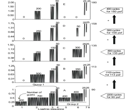
A Special Interest Group for Dynamic Evaluation of Roofing Systems - SIGDERS has been established at the NRC to develop a test standard for evaluating roofing systems under dynamic conditions. The dynamic load cycle developed by SIGDERS is shown in Figure-1 and it was applied for all the investigations in this study. The dynamic loading sequence has five rating
levels (A to E). To evaluate the ultimate strength of the roofing system, testing should start at Level A, and continually proceed through each test sequence incrementally from one level to another. To obtain a rating, all specified number of gusts in each level should be completed successfully, without causing failure or damage to the roof system. The test pressure used in the testing may be determined from building code requirements for a specific building, or it may be a pressure specified by the proponent. Using this value, the test pressure ratios shown in Figure-1 can be converted into test pressures. Based on the National Building Code of Canada Figure-1995, roof design wind uplift pressures were calculated for all major cities in the province of British Columbia. Based on the above calculations, a test pressure of 4309 Pa (90 psf) was selected for the investigations. This resulted in wind gusts with peak pressure intensity ranging from 1077 Pa (23 psf) to 8618 Pa (180 psf). The detailed procedure followed for the development of the SIGDERS load cycle is documented [8].
500 0 150 50 0 350 250 0 150 50 0 300 2525 1.50 1.13 0.75 0.38 0 250 0 100 50 0 50 2525 1.75 1.31 0.88 0.44 0 200 0 100 50 0 0 25 25 2.00 1.50 1.00 0.50 0 1.25 0.63 0.31 0 0 94 500 cycl s for 158 psf 400 cycles for 180 psf 800 cycles f or 135 psf 1100 cycles for 113 psf 2200 cycles for 90 psf 25 25 0 0.25 0.5 0.75 1 400 700 200 50 400 400 2525 1 2 3 4 5 6 7 8 Loading sequence Group 1 Gr oup 2 Number of gust s + + + + + + + + A B C D E T e st P ress u re R at io s . 90 113 135 158 180
Figure 1 SIGDERS Dynamic Wind Load Cycle
2.2 Investigated Panel Configurations
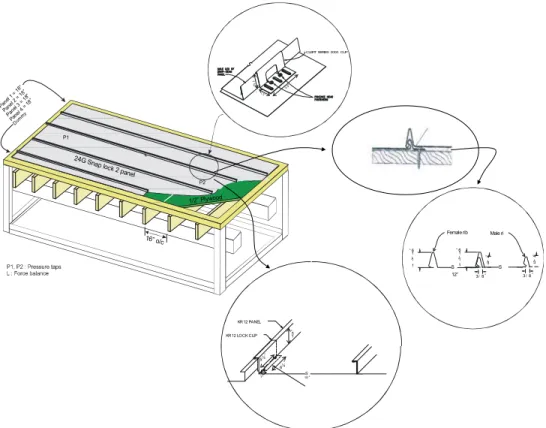
Twenty roof systems having three different interlocking configurations were investigated. Cross-sectional representations of the typical test assembly and details of the attachments are shown in Figure-2.
• SNAP LOCK 2 panel has a 44 mm (1¾ in.) rib height and a net width of 457 mm (18 in.). Each panel was mechanically attached to the deck with CLERT SERIES 2000 clips. The clips were 44 mm (1¾ in.) in height, 89 mm (3½ in.) in length and 38 mm (1½ in.) in width. Two, #12 x 25 mm (1 in.) pan head fasteners were used per clip to fasten the panels to the deck. The clips were spaced either 406 mm (16 in.) or 610 mm (24in.) apart along the seam length of the panel.
• PROLOCK panel has a 27 mm (1-1/16 in.) rib height and a 19 mm (¾ in.) rib height and a net width of 305 mm (12 in.). The female rib was aligned over the male rib, and a rubber mallet was used to tap the female rib to engage the panels. Phillips fasteners with
head type #8 x 25 mm (1 in.) were placed at a spacing of 343 mm (13½ in.) or 318 mm (12½ in.) on center along the male side of the panel to fasten the flanges to the wood decking.
• KR-12 panel has a 38 mm (1½ in.) rib height and a net width of 406 mm (16 in.), 457 mm (18 in.) or 508 mm (20 in.). The panel has a zinc-alloy coated (galvanized) exterior finish. A mechanical seaming tool locks the seams securely. The dimensions of the panel clips used for this system were 49 mm (1-15/16 in.) x 159 mm (6¼ in.) x 25 mm (1 in.) (height x length x width). Two #12 x 25 mm (1 in.) fasteners were used per clip to fasten the panels to the deck. The clips were spaced 357 mm (18 in.) or 24 in. apart along the seam length of the panel.
Each configuration develops different locking mechanisms when the two panels are overlapped. As a roof cover, one of the main requirements is to provide water tightness when the panels are locked. However, the present study focuses only on the panel’s resistance to wind fatigue.
“ 3/ 8“ 1 1 / 1 6 “ “ 3/8“ 1 1 / 1 6 “ S S 3 / 4 3 / 4 12” Female rib Maleri 1 5 “ KR 12 PANEL KR 12 LOCK CLIP 6¼“ “ S“ 5¼“ 1/2” Plywood 24G Snap lock 2 panel Pane l 1 = 18” Pane l 2 = 18” Pane l 3 = 18” Pane l 4 = 18” L P1 P2
CLERT SERIES 2000 CLIP
3.5” 1 ¾ “ 16” o/c Dum my
Figure 2. Investigated panel configurations for wind uplift testing
2.3 Simulated Deck Conditions
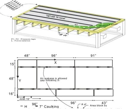
Three groups of deck conditions (airtight, air permeable and air permeable with underlay) were simulated. Air leakage ratios, AL (leakage area / deck area), for the simulated conditions ranged from 0.12% to 2.4% for the air permeable deck condition to approximately 0.05% or less for the air-tight deck condition. The details for each deck condition are summarized in Table 1.
• Group 1- Air-Tight Deck: As shown in Figure-3-a, five sheets of 16 mm (5/8 in.) tongue and grooved plywood were installed over the 51 mm (2 in.) x 254 mm (10 in.) joists. This simulated an airtight deck condition.
• Group 2 – Air-Permeable Deck: To simulate different ratios of the air-permeable deck conditions, three approaches were used. To simulate air leakage, when using tongue and grooved plywood, a number of holes (24 mm (15/16 in.) diameter) were placed through the wooden deck (Figure-3-a). H-clips were used between the 13 mm (1/2 in.) plywood sheets that were installed over the over the 51 mm (2 in.) x 254 mm (10 in.) joists, to simulate field construction details. The spacing between the plywood sheets that was created by the H clips provided a pathway for airflow. Caulking strips were applied at preferential locations to block the gap between the plywood sheets and reduce the air leakage ratio. A typical layout of the structural deck with air leakage ratio, AL, of 0.13% is shown in Figures-3-b.
Dummy= 3“ Panel1 =18” Panel2 =18” Panel3 =18” Panel4 =18” Dummy =15” L P 1 P 2 24G KR 18 panel 24”o/c
5/8” tongue& grooved
48” 96” 43” 15” 48” 91” 96” 96” H 16” Joist 16”
A = {Leakage A rea/D eck A rea} x 100= {0.08 x (235 x 2 - 1.5 x 32 - 7 x 16)} / L z
A ir leakage is allowed gap following
X-# of A rea block by 7” C aulking
A rea block by caulking X
Y
Figure 3. Different deck configurations and calculation of simulated leakage conditions.
• Group 3 - Air Permeable Deck With Underlay: As shown in Figure-3-c, the roof systems
were built with either a self adhered modified bituminous or No. 30 organic saturated felt paper as an underlay between the wooden deck and metal panel. The underlay sheets were loose laid or adhered to the plywood with a 102 mm (4 in.) wide overlap between the sheets.
Panel
Width Clip Spacing Joist Spacing
Wind Uplift Resistance
System Panel Type AL %
mm in mm in mm in Pa psf 1 KR-12 0 406 16 610 24 610 24 5746 120 2 KR-12 0 457 18 610 24 610 24 5746 120 3 KR-12 0.09 508 20 457 18 610 24 5410 113 4 KR-12 0.27 457 18 457 18 610 24 1101 23 5 KR-12 2.4 508 20 508 20 610 24 718 15 6 KR-12 2.4 305 12 305 12 610 24 1436 30 7 SNAP LOCK 2 0.09 457 18 457 18 610 24 6464 135 8 SNAP LOCK 2 0.13 457 18 457 18 406 16 2155 45 9 SNAP LOCK 2 0.14 457 18 457 18 406 16 2155 45 10 SNAP LOCK 2 0.18 457 18 457 18 406 16 2155 45 11 SNAP LOCK 2 2.4 457 18 457 18 610 24 2155 45 12 PRO LOCK 0 305 12 305 12 610 24 5410 113 13 PRO LOCK 2.4 305 12 305 12 610 24 2155 45 14 SNAP LOCK 2* 0.18 457 18 457 18 406 16 2155 45 15 SNAP LOCK 2* 0.11 457 18 457 18 406 16 2155 45 16 SNAP LOCK 2** 0.13 457 18 457 18 406 16 3256 68 17 SNAP LOCK 2** 0.11 457 18 457 18 406 16 4309 90 18 PRO LOCK* 0.11 305 12 305 12 406 16 3256 68 19 PRO LOCK* 0.08 305 12 305 12 406 16 2155 45
* Systems with asphalt impregnated felt paper underlay; ** Systems with self adhered modified bituminous
3 RESULTS AND DISCUSSION
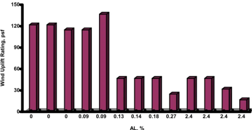
All the experiments for the present study were carried out at the Dynamic Roofing Facility (DRF), located at the National Research Council (NRC) campus in Ottawa, Canada [9]. For each experiment, sensors were installed, at selected locations, to measure the system’s response during wind testing. Time histories of the applied test pressure and induced load on the fasteners, as well as the deflection of the panel were collected and analyzed [10-12]. Wind uplift ratings assigned to the tested assemblies without underlay, namely Group 1 and Group 2 are summarized in Figure-4. The data obtained for 13 different system configurations as listed in Table 1 is represented in Figure-4. It is evident that the deck air-leakage ratio is the main factor influencing the wind uplift rating. The presented data can be grouped into two sets, one set representing data when AL is less than 0.1% and a second set when the AL is more than 0.1 %. A similar comparison can be made with this data to the classification of the simulated deck conditions, i.e. airtight decks (0% ≥AL≤0.05%) and air permeable decks (0.12 ≥AL ≤ 2.4%). It is also evident that there are dramatic decreases in the wind uplift rating when the AL increases from 0.1% to higher values. The data from three different panel configurations are also presented in Figure 4 without differentiation. It appears from this data that despite differences in the panel configurations or any other parameter, the only significant effect on the wind uplift rating amongst the tested systems results from differences in AL.
0 30 60 90 120 150 Wind U p lift R a ting, ps f 0 0 0 0.09 0.09 0.13 0.14 0.18 0.27 2.4 2.4 2.4 2.4 AL, %
Figure 4. Effect of air leakage on the wind uplift resistance of the tested systems.
As shown in Figure 5, failure modes of the systems were also investigated after the wind test. Typically, three different failure modes were observed, according to the three different deck conditions. Systems with airtight deck configurations failed due to deck failure from the direct transfer of load from the panels to the deck. In other words, the fastener attachment of the deck pulled out from the joist. In all cases of airtight decks, the interlocking mechanisms of the panels or the attachment of the panel to the deck was not the weakest link to the wind dynamics.
In the case of the systems with air permeable decks (Group 2), the panel interlocking mechanism opened or separated during the wind loading cycles. As shown in Figure 5, a measurable amount of panel deflection was noticed for all systems categorized under Group 2. For Group 3 configurations, systems with felt paper as underlay performed similar to the systems of Group 2. However, the performance response of the systems with peel and stick as underlay were similar to the airtight configurations in achieving wind uplift rating. In other words, the weakest link causing system failure for those systems with peel and stick as underlay was the panel fastener pullout from the wooden deck.
Panel 2 Panel 3
Clip
Figure 5. Typical failure modes of the investigated system.
F ast e n er p ull o ut
In this section, a simplified procedure has been developed for designing flat, mono slope and saw tooth roof assemblies with metal coverings located in the province of British Columbia. Designers are directed to use building codes for detailed wind load calculations. This simplified procedure has conservative assumptions, and it is based on the National Building Code of Canada, 1995, Experimental data, Engineering directives, and Inputs from industrial clients [13].
Step 1 - Calculate the design wind pressure
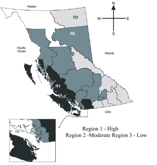
Step 1.1: Figure 5 divides the province of British Columbia into three regions. Locate the proposed building location in Figure 5 and identify the one of the following three regions.
Region 1 - High
Region 2 -Moderate Region 3 - Low
USA Alberta Alaska Pacific Ocean N E W S
Figure 5. Wind pressure zone for the province of British Columbia.
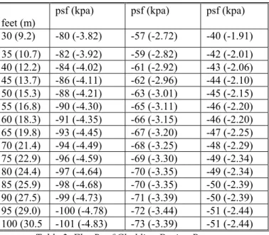
Step 1.2: Low-rise buildings with flat roof: For building height less than building width with flat roofs design pressures are given in Table 2. Based on the building height and region, select the design pressure for roof covering design.
Step 1.3: Low-rise buildings with mono slope roof: For building height less than building width with roof slopes that are greater than 3o and less than 10o.
Design Pressure = 0.90 X Design Pressure reported in Table 2. (1)
feet (m)
psf (kpa) psf (kpa) psf (kpa) 30 (9.2) -80 (-3.82) -57 (-2.72) -40 (-1.91) 35 (10.7) -82 (-3.92) -59 (-2.82) -42 (-2.01) 40 (12.2) -84 (-4.02) -61 (-2.92) -43 (-2.06) 45 (13.7) -86 (-4.11) -62 (-2.96) -44 (-2.10) 50 (15.3) -88 (-4.21) -63 (-3.01) -45 (-2.15) 55 (16.8) -90 (-4.30) -65 (-3.11) -46 (-2.20) 60 (18.3) -91 (-4.35) -66 (-3.15) -46 (-2.20) 65 (19.8) -93 (-4.45) -67 (-3.20) -47 (-2.25) 70 (21.4) -94 (-4.49) -68 (-3.25) -48 (-2.29) 75 (22.9) -96 (-4.59) -69 (-3.30) -49 (-2.34) 80 (24.4) -97 (-4.64) -70 (-3.35) -49 (-2.34) 85 (25.9) -98 (-4.68) -70 (-3.35) -50 (-2.39) 90 (27.5) -99 (-4.73) -71 (-3.39) -50 (-2.39) 95 (29.0) -100 (-4.78) -72 (-3.44) -51 (-2.44) 100 (30.5 -101 (-4.83) -73 (-3.39) -51 (-2.44)
Table 2. Flat Roof Cladding Design Pressure
Step 1.4: Low-rise buildings with Saw-Tooth roof: For building height less than building width with the roof slopes that are greater than 10o and less than 30o:
Design Pressure = 1.34 X Design Pressure reported in Table 2. (2)
Step 1.5:Medium rise buildings with flat roof: For building height greater than building width:
Design Pressure = 1.05 X Design Pressure reported in Table 2. (3)
Step 1.6:Wind Uplift Pressure = Design Pressure X Factor of Safety.
NBC, 1995 recommends minimum design values. Selecting an appropriate factor of safety depends on the designer, and it should be 1.0 or higher.
Step 2 - Reduction factor calculation for air permeable deck constructions
When deck construction permits air to pass through openings or joints ( air leakage), there will be a significant reduction in the wind uplift resistance of the roof covering. One can minimize this effect by using an air barrier that is adhered to the deck prior to the installation of the covering and by sealing perimeters, penetrations and junction flashing. Some air permeable deck constructions include the following: re-roofing applications, acoustical steel decking, unblocked (or) non-tongue and grooved wood decking, precast concrete and gypsum planks without grouted joints and cementitious wood fiber planks.
Step 2.1: Calculate the ratio of leakage area by using the following formula:
AL = {Leakage area / Deck area}*100, % (4)
For example, conventional deck constructions, i.e., new 16 mm (5/8 in.) tongue and groove plywood has AL ≅ 0%, and for 13 mm (½ in.) plywood installed with H clips AL can be varied based on roof dimension, number of boards used, and clip locations.
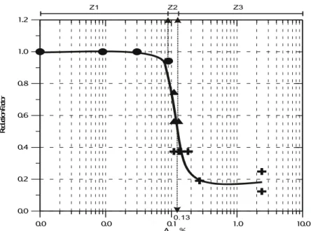
Step 2.2: Using Figure-6, quantify a reduction factor that can account for the air permeable deck constructions. The horizontal axis shows the AL in percentage and the vertical axis displays the reduction factors. The selected reduction factor should fulfill the following criteria:
0.0 0.0 0.1 1.0 10.0 A , % 0.0 0.2 0.4 0.6 0.8 1.0 1.2 Re du cti on F ac to r L 0.13 Z1 Z2 Z3
Figure 6. Reduction factor vs. air leakage ratio, AL.
Note: These reduction factors were developed based on limited experimental data. It can be observed that the resistant wind pressure is increasing dramatically as the air leakage ratio is
decreasing. It can also be estimated that a critical zone exists between 0.09% ≤ AL ≤ 0.27%. For
air leakage zone, Z1 (0.0% ≤ AL ≤ 0.09%), all tested metal panel systems can be used with
organic saturated felt paper or peel & stick ice and water shield sheet underlay. For air leakage
zone, Z2 (0.09% < AL ≤ 0.13%), SNAP LOCK 2 (with panel width smaller and equal to 18 in.)
and PROLOCK (with panel width smaller and equal to 12 in.) metal panel systems should be used with a self adhered modified bituminous Ice and Water Shield as underlay. KR-12 panel system or organic saturated felt paper underlay should not be used for this air leakage zone. For
air leakage zone, Z3, (AL > 0.13%), all tested metal panel systems should be used with organic
saturated felt paper or a self adhered modified bituminous Ice and Water Shield underlay only for Region 3 in Figure 5.
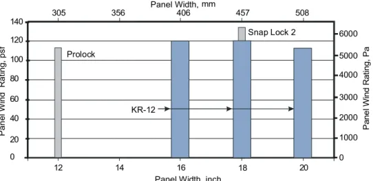
Step 3 - Identifying a suitable panel configuration
Using Figure 7, select a panel configuration and its wind uplift rating. This rating represents a conservative scenario of metal coverings installed over airtight deck configuration. Therefore, calculate the actual wind uplift resistance as follows:
Wind Uplift Resistance = Panel Wind Rating X Reduction Factor (6)
Step 4 - Wind uplift design
Wind Uplift Resistance > Design Wind Pressure or Value obtained from the Step 3 > Value obtained from the Step 1.6
5 CONCLUSION
Air permeability of the structural deck is an important factor for wind uplift performance of the architectural metal roofing systems. Application of a self-adhered modified bituminous underlay improves the wind uplift performance. Based on the extensive experimental data, a simplified design procedure was developed. The presented data was limited to metal roofing systems installed over wooden decks. Investigations are in progress over steel deck composite assemblies.
Prolock Snap Lock 2 KR-12 P a n e l W in d R a ti n g , p s f 12 14 16 18 20 0 20 40 60 80 100 120 140 1000 2000 3000 4000 5000 6000 0 P a ne l Wind R a ti n g , P a
Panel Width, inch Panel Width, mm
305 356 406 457 508
Figure 7. Wind rating vs. panel width
6 REFERENCES
1. Specification for the design of cold-formed steel structural members (1989), American Iron and Steel Institute, Washington, DC, USA.
2. Design of steel structures – Part 1.3 – Cold Framed thin gauge members and sheeting (1992), Euro code 3, Commission of the European Communities, Brussels, Belgium.
3. Cold Formed Steel Structures Code (1996) – AS/NZS4600, Standards Australia, Sydney, Australia 4. Schroter. R.C (1985), “ Air Pressure Testing of Sheet Metal Roofing”, National Symposium on Roofing
Technology, NRCA/NIST, Washington, D.C., U.S.A., pp. 254-260
5. Mahendran.M (1990), “Fatigue Behavior of corrugated roofing under cyclic wind loading”, Civil Engineering Trans, Canberra, Australia. 32 (4), 219-226.
6. Meyers.L.R, Koziol.S.R.,Johnson. K. D and Krogstad.V.N., (1997), “ Laboratory Testing of Low Slope Standing Seam Metal Roof Application”, Fourth International Symposium on Roofing Technology, NRCA/NIST, Washington, D.C., U.S.A., pp. 144-152.
7. Mahendran.M (1997), “Review of current test methods for screwed connection”, Journal of Structural Engr., ASCE, 123 (3), 321-325.
8. Baskaran, Y. Chen, and U. Vilaipornsawai, “A New Dynamic Wind Load Cycle to Evaluate Mechanically Attached Flexible Membrane Roofs”, Journal of Testing and Evaluation, ASTM, July 1999
9. Baskaran, A. and Lei, W. (1997), “A New Facility for Dynamic Wind Performance Evaluation of Roofing Systems”, Proceedings of the Fourth International Symposium on Roofing Technology, NRCA/NIST, Washington, D.C., U.S.A., pp. 168-179
10. Ham, H.J and Baskaran, A., Wind Uplift Resistance of Metal Roof – Phase I, NRC Client Report B1040.1, 22 August 2000.
11. Ham, H.J and Baskaran, A., Wind Uplift Resistance of Metal Roof – Phase II, NRC Client Report B1040.2, 64, February 2001.
12. Baskaran. A and Ham. H., Simplified Design Procedure for Wind Uplift Resistance of Roofing Systems with
Metal Coverings., NRC Client Report B1040.3, 10 March 2001.
13. Ham, H.J., Baskaran, .A.,, "Wind uplift resistance of architectural metal roofing system," International Conference on Building Envelope Systems and Technology (ICBEST) (Ottawa, Ontario, 2001-06-26), pp. 37-38, Jul, 2001
7 ACKOWLEDEMENT
This was a joint research project between Roofing Contractors Association of British Columbia and NRC/IRC. The authors appreciate contribution of Mike Sexton and William Lei, Technical Officers at NRC.