CONCEPTUAL DESIGN OF MEMBRANE STRUCTURES
BY
VITTORIO C. AGNESI
BACHELOR OF SCIENCE IN CIVIL ENGINEERING JUNE 1997
SWARTHMORE COLLEGE
SUBMITTED TO THE DEPARTMENT OF CIVIL AND ENVIRONMENTAL ENGINEERING IN PARTIAL FULFILLMENT OF THE REQUIREMENTS FOR THE DEGREE OF
MASTER OF ENGINEERING IN CIVIL AND ENVIRONMENTAL ENGINEERING AT THE
MASSACHUSETTS INSTITUTE OF TECHNOLOGY
MAY 1998
Copyright © 1998 Massachusetts Institute of Technology All Rights Reserved
SIGNATURE OF AUTHOR
---VITTORIO C. AGNESI
MAY 8, 1998
CERTIFIED BY ---
---V1 JEROME J. CONNOR
PROFESSOR, DEPARTMENT OF CIVL AND ENVIRONMENTAL ENGINEERING THESIS SUPERVISOR
APPROVED BY --- ---JOSEPH M. SUSSMAN
CHAIRMAN, DEPARTMENTAL COMMITTEE ON GRADUATE STUDIES
CONCEPTUAL DESIGN OF MEMBRANE STRUCTURES
BY
VITTORIO
C.
AGNESISUBMITTED TO THE DEPARTMENT OF CIVIL AND ENVIRONMENTAL ENGINEERING ON
MAY 8, 1998
IN PARTIAL FULFILLMENT OF THE REQUIREMENTS FOR THE DEGREE OF MASTER OF ENGINEERING IN CIVIL AND ENVIRONMENTAL ENGINEERING
ABSTRACT
Since the introduction of the contemporary tensile structures in the 1950's, technological advances throughout the decades have lead to dramatic improvements over their early counterparts. Membrane structures are a class of tensile structure that require the entire surface to remain in tension and have opposing radii of curvature in order to maintain stability. Improved membrane strength and corrosion resistance in synthetic fabrics and films have allowed architects and engineers to create permanent and large-scale structures using this technology. However, the non-linearity, complexity in fabrication, and performance characteristics of membranes has limited their application.
The affordability and speed of computing power in the 1990's is changing the way membrane structures are designed and manufactured. The early membrane structures were designed using physical models to explore the curved surfaces inherent in membrane structures. Improved modeling capabilities on computers, along with information obtained from observations of existing membrane systems, are providing architects and engineers with the ability to explore efficient and innovative solutions. Computer modeling is also reducing the time required for the design of membrane structures, allowing them to compete on a cost-basis with conventional structural solutions.
The information contained in this thesis is intended to provide an introduction to the considerations that go into the design and suitability of membrane structures in various environments, with special emphasis on their incorporation into the urban context. The design of membrane structures is not covered by any building Code, and thus remains the product of specialized firms. However, commercially available computer-modeling packages (such as the one used in this thesis) and a better understanding of the behavior of these structures under service conditions, will undoubtedly lead to an increasing number of firms utilizing these exciting structures to solve the challenges of our built environment.
THESIS SUPERVISOR: JEROME J. CONNOR
ACKNOWLEDGMENTS
I would like to thank Prof. Jerome J. Connor and Charles H. Helliwell for their guidance and input throughout the Masters of Engineering program, and for giving me the opportunity to work with them in the management of the term project. I would also like to thank Erik Moncrieff from Technet-gmbh in Berlin, and the people in the Building Technology program in MIT: Chris Luebkeman and Dale Clifford. Special thanks to all those friends at MIT who helped me with this project, and made working on this thesis fun.
To my family, I reiterate my sentiments about your role in my life: all that I am, I owe to you.
TABLE OF CONTENTS
LIST OF FIGURES LIST OF TABLES SECTION I CHAPTER 1 CHAPTER 2 CHAPTER 3 SECTION II CHAPTER 4 CHAPTER 5 CHAPTER 6 REFERENCESINTRODUCTION & DESIGN CONSIDERATIONS
INTRODUCTION TO MEMBRANE STRUCTURES
1.1 Background
1.2 Classification of Tension Structures 1.3 Behavior of Tension Structures 1.4 History
1.5 Incorporation Into the Urban Setting PERFORMANCE CONSIDERATIONS
2.1 Loads and Climate 2.2 Fire Safety
2.3 2.4 2.5
Acoustic Performance
Maintenance, Durability, and Inspection Cost Issues CHARACTERISTICS OF FABRICS 3.1 Fabric Types 3.2 Fibers 3.3 Coatings 3.4 Membrane Properties
THE DESIGN PROCESS
FORM DETERMINATION
4.1 Basic Design Principles 4.2 Physical Modeling 4.3 Computer Modeling
ANALYSIS & DESIGN
5.1 General Parameters 5.2 Analysis Using EASY
PATTERNING AND FABRICATION
6.1 General Patterning Information 6.2 Tendon Selection and Specification 6.3 Connections
LIST OF FIGURES
CHAPTER 1 Figure 1.1 Figure 1.2 Figure 1.3 Figure 1.4 Figure 1.5 Figure 1.6 Figure 1.7 Figure 1.8 CHAPTER 2 Figure 2.1 CHAPTER 3 Figure 3.1 CHAPTER 4 Figure 4.1 Figure 4.2 Figure 4.3 Figure 4.4 Figure 4.5 Figure 4.6 Figure 4.7 Figure 4.8 Figure 4.9 Figure 4.10 Figure 4.11 Figure 4.12 Figure 4.13 CHAPTER 5 Figure 5.1 Figure 5.2 Figure 5.3 Figure 5.4 Figure 5.5 Figure 5.6 CHAPTER 6 Figure 6.1 Figure 6.2 Figure 6.3 Figure 6.4 Figure 6.5 Figure 6.6The family of tensile structures.
Double curvature (anticlastic) of a tensile structure. The 1955 music pavilion at Kassel, Germany. Olympic stadium in Munich.
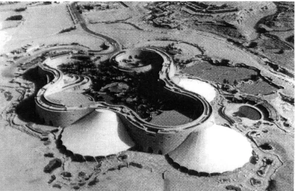
Hajj Terminal, Jeddah, Saudi Arabia. Diplomatic Club in Riyadh.
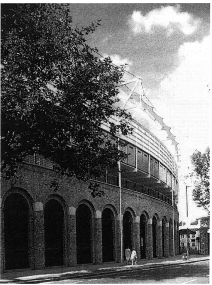
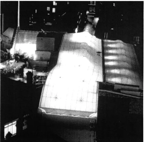
Mound Stand, Lord's Cricket Ground in London Imagination canopy roof in London, England.
Acoustic diagram for the first Pier Six Music Pavilion, Baltimore.
Typical diagram of fabric weaving.
Diagram showing the principal of membrane. Four-point saddle shape membrane diagram. Stages of the design of tensile structures. Soap film model with an internal support. Plan view of the boundary cables using EASY. Isometric view of the boundary cables in EASY. Typical edge cable detail.
Tendon terminations at Il Grande Bigo, Genoa.
Dialogue box for editing boundary lines in FRONTEND. Net parameter dialogue box in FRONTEND.
Isometric view of the four-point membrane structure. Isometric view of the membrane structure with finer mesh. Isometric view of the surface generated by FRONTEND.
Sample membrane tent structure showing internal support. Four-point membrane structure with supports.
Stress distribution (plan view) for unloaded membrane structure. Deflection comparison for loaded membrane structure.
Deflection comparison for modified membrane structure. Stress distribution for modified membrane structure.
Sample patterning output for Buckingham Palace ticket office. Typical mechanical joints for membrane structures.
Typical seam width arrangement. Typical clamping arrangement.
Plan view of a typical perimeter connection scheme. Sketch of a pipe arch supporting a membrane seam.
Steel pipe support with a fixed fabric. Cable cuff arrangement diagram. Cable clamping arrangement.
Sectionalizing details for membranes. Common methods of tendon terminations.
A toggle fork that allows movement in two planes. Figure 6.7 Figure 6.8 Figure 6.9 Figure 6.10 Figure 6.11 Figure 6.12
LIST OF TABLES
CHAPTER 3 Table 3.1 Table 3.2
Typical uniaxial breaking strength of glass & polyester fibers. Properties of glass & polyester membranes.
SECTION
I
CHAPTER
1
INTRODUCTION TO MEMBRANE STRUCTURES
1.1
Background
Contemporary membrane structures are part of an ever-changing technology, which is allowing engineers and architects to explore new forms and create innovative solutions for an increasingly complex world. Tensile structures possess many properties that are not attainable using traditional design materials and geometrical arrangements. The suitability and feasibility of these structures should be carefully studied for each application, with special emphasis on performance, cost, and aesthetic characteristics.
Tensile structures are attractive to the designer wishing to demonstrate structural efficiency. Pure tension is by far the most efficient way of using a slender member, as the same member will fail at loads well below its ultimate strength in compression due to buckling. A member subjected to bending will do the same due to the generation of internal stresses that are very high in relation to the applied load. Tensile structures are also appealing because of their aesthetic properties, offering the possibility to contrast the typical "brutal" forms of architecture present in most concrete-dominated cities. Thus, tensile structures are a true physical representation of the combined effort of the structural engineer and architect.
1.2
Classification of Tensile Structures
Technological advances in the second half of this century have made the design and construction of tensile structures a feasible option for designers. This innovation has also brought with it the need to define and classify a broad range of different systems that can be considered tensile structures. Recent publications seem to have converged on a definition and classification that can be used by all disciplines involved in the process of
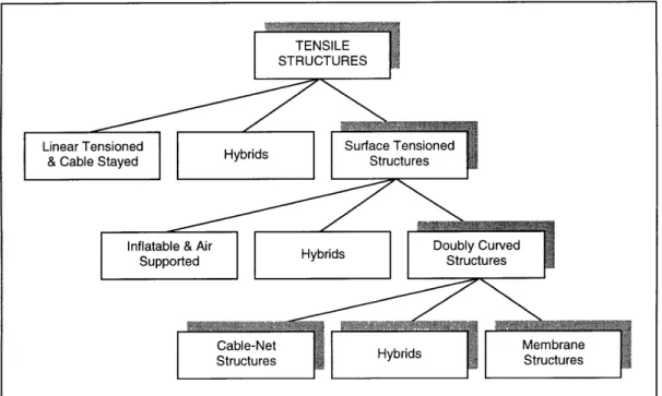
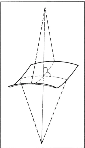
building tension structures. Tensile structures are ones in which the principal load-carrying members transmit the applied loads to the supporting structures or foundations by direct tensile stress without flexure or compression [16]. They are load-adaptive in that members change their geometry to accommodate changes in load rather than increase stress levels [5]. Figure 1.1 shows a breakdown of tensile structures into general classes of structures, although some structures may not conform to this categorization [ 11]. This report focuses on membrane structures, which are designed and behave much like cable-net structures, and fall within the category of doubly-curved structures. A doubly-curved structure is referred to here as one having curvatures in mutually opposite directions at every point of the surface of the membrane (see Figure 1.2).
TENSILE STRUCTURES
Linear Tensioned Hybrids Surface Tensioned & Cable Stayed Structures
Inflatable & Air Doubly Curved
Supported Hybrids Structures
Cable-Net Membrane
Structures Hybrids Structures
Figure 1.1 The family of tensile structures.
The definition of a membrane structure varies from one publication to the next, with the most controversial argument being that air-supported structures are also membrane structures. In general, however, these air-supported structures are now considered to be a special class of surface tensioned structure, also referred to as a pneumatic structure. Pneumatic structures are technically doubly-curved structures, but are synclastic (principal curvatures at a point are in the same direction). A broad
definition given by ASCE is: "A membrane structure is defined as a structure made of a thin, flexible membrane that is held in shape by the application of tension forces, and acting simultaneously as structure and as a weather shield [12]."
Figure 1.2 Double curvature (anticlastic) of a Figure 1.2 Double curvature (anticlastic) of a tensile structure.
1.3
Behavior of Tension Structures
The reduced stiffness characteristic of tension structures makes them susceptible to large motions due to concentrated loads and dynamic effects. Tension structures achieve their stiffness through curvature and pre-stressing, and respond in a nonlinear fashion to both pre-stressing loads and in-service forces. This nonlinear behavior is independent of the linearity of the material or the applied loads. Pre-stressing forces are those forces (edge loads, self-weight, or pressure) which act on a predominant configuration of static
r
a
I
/ / /
equilibrium for the structure [16]. These pre-stress forces stabilize the structure and provide the stiffness required to resist further deflection. The response of a tension structure to pre-stressing is always nonlinear in that the equilibrium configurations, as well as the state of stress in the members, are dependent on the pre-stressing forces.
In-service forces are those variable live loads, static or dynamic, which are expected to occur regularly within the life of the structure. Each loading condition is superposed upon the pre-stressing forces. Because the response to in-service forces by tension structures is highly non-linear, superposition of the results for different loading conditions cannot be considered a reliable analysis technique. The non-linearity of tension structures is due mainly to the geometrical changes under applied loads, and thus the materials are usually assumed to behave linearly. There are some special cases for which non-linear behavior of materials should be considered and the overall performance of the structure under the applied loads reevaluated. Some examples of these cases are hyperelastic and viscoelastic behavior or polymer cables and membranes, non-isotropic woven fabrics, and thermal-elastic and elastoplastic behavior under extreme loads [5]. Another special case for non-linear behavior of tension structures that may arise is the interaction with hydrostatic and hydrodynamic loads. The magnitude of the drag force in these cases is non-linear, and the pressure loads depend on the orientations of the cable axes and membrane surface, which undergo significant rotations during loading.
1.4
History
TRADITIONAL MEMBRANE STRUCTURES
In terms of architectural function, membrane structures are the oldest dwelling except for the cave or the occasional hollow tree. Examples of these early tents or awnings include the native American tepee, the Mongolian yurt, and the Black Tent used by desert nomads of the Sahara, Arabia, and Iran. However, in terms of structural performance and appearance, the stressed surface of a nautical sail is a more accurate analogy [16].
The period between Roman times and the nineteenth century saw little advancement of the tent, perhaps because of a lack of demand or because of the lack of improvement in the strength of cables, textiles, and joints. The industrial revolution
changed these conditions, bringing a demand for large and portable structures (used for mass entertainment such as circuses) and the availability of stronger and cheaper materials.
TWENTIETH-CENTURY INNOVATIONS
The examples mentioned above drew their stability from a combination of guy ropes, self-weight, and the inherent stiffness of the comparatively thick, heavy materials. These less efficient materials and limited geometrical arrangements produced structures that were relatively slack and far from being considered durable structures. A new breed of membrane structures emerged after the second world war: lightweight and flexible structures with stability derived not from self-weight or stiffness, but by careful attention to curvature and deliberately induced pre-stressing forces.
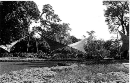
There were two principal innovators during the early stages of modern tensile structures, and much of the success of tension structures is attributed to their early works. In the 1950's, architect and engineer Frei Otto developed a theory for the design of pre-stressed fabric structures [11]. With support from the German tent manufacturing company Stromeyer, Otto and his colleagues produced a large number of small-scale experimental fabric structures between 1955 and 1972 [11]. The first of these innovative structures was the simple music pavilion at the Federal Garden Exhibition at Kassel in 1955 (see Figure 1.3). This simple four-corner surface structure was made of a cotton canvas stretched between two high and two low points creating a dynamic, doubly-curved form.
Figure 1.3 The 1955 music pavilion at Kassel, Germany.
These new structures, most of which were temporary, introduced new ideas about shape, erection techniques, stressing methods, material limitations, and connections. The combination of steel cables with fabric structures allowed for larger spans to be covered, while decreasing the stress levels in the membrane. The first notable use of tension structures in a permanent and large-scale application was for the 1972 Olympic Stadium in Munich (see Figure 1.4).
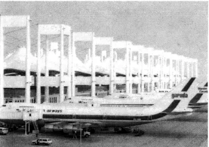
The membrane materials available to Frei Otto during this time allowed for only a very limited span to be covered, and with a short life expectancy. At present, as a result of large advances in textile technology, there are many built examples of impressive scale, such as the Hajj Terminal in Saudi Arabia (see Figure 1.5). These new membranes have very high tensile strengths, excellent fire resistance, and life expectancies of twenty-five years or more [16].
Figure 1.5 Hajj Terminal, Jeddah, Saudi Arabia.
1.5
Incorporation Into the Urban Setting
Before the Olympic stadium in Munich, most of the pre-stressed surface structures
remained consigned mainly to temporary canopies and pavilions at expositions and trade fairs. This created the association of tensile structures with non-permanent systems, rather that permanent and fully enclosed buildings [ 11]. The reason for many architects avoiding the implementation of tensile structure in their designs may stem from the
suitability of membrane structures to natural settings and their temporary appearance. Other possible reasons include the difficulties of architects to reconcile the curved lines
of tensile structures with the more conventional rectilinear construction of our cities, or simply a lack of understanding of these relatively new structures.
Before 1986, the superposition of membrane structures with traditional architecture had only been accomplished for buildings with curved walls or plan. Some examples of these are the famous Olympic Stadium in Munich, and the Diplomatic Club in Riyadh (Figure 1.6). The challenge remained for architects to determine how and when to incorporate the curved surfaces of tension structures with the rectilinear geometries of conventional structures. Many of the early projects that attempted to do this resulted in a combination that looked rather like a poorly fitting tent attached to a simple shed.
Figure 1.6 Masonry construction in combination with structural membranes and cable-nets, built to house the Diplomatic Club in Riyadh.
Shortly after 1986, several examples appeared throughout the world of combined structures, such as the small Cricket Ground in London (Figure 1.7). Lord's Cricket Ground is set in a traditionally built area of London, and is owned and run by a long-established and conservative organization. When a new grandstand was needed, the use of a membrane structure was proposed in order to evoke images of the traditional village cricket marquee [11]. The success of this building provided a clear example that appropriately used membrane roofs could make an architecturally satisfying contribution
within the urban context. Establishing what constitutes the "appropriate use" of membrane structures is of course subjective to each culture and architecture style.
Figure 1.7 Mound Stand, Lord's Cricket Ground, London.
Because the structure at Lord's Cricket Ground used an open membrane, a significant building within a traditional urban setting that combined a membrane or cable-net supported roof with conventional construction while enclosing an environmentally conditioned space had yet to appear. However, about two years after the completion of the Cricket Ground in London, the headquarters building for Imagination in west London answered many of the remaining questions (Figure 1.8). The tension structure transformed a gap between two buildings into a useful and insulated space, demonstrating that fabric roofs need not be considered only where large spans are involved.
Figure 1.8 At Imagination, the tensile canopy provides environmental control for the gallery and atrium, and also forms an integral part of the image of the new building.
Most building structures are clad in some manner and hidden from view, making connection detailing and element appearance of little concern to architects. However, the means by which a fabric roof is supported and its appearance are inseparable. Supporting masts are usually left exposed, and steel cables pass through space or lay against the fabric so that they remain visible from either above or below the roof [12]. Even the patterns made by the seaming of the fabric can be used to reflect predominant stress patterns-a strong visual element of the design. Although urban tensile architecture is still in its infancy, contemporary structures are a great improvement over those from the 1950s and 1960s. The availability of stronger and more durable materials, along with a greater understanding of the performance and design tools of tensile structures, should allow for greater experimentation with incorporation into the urban setting by architects. As we head into the next century, overcoming the architectural and technical difficulties
of combining tensile structures with conventional architecture, will no doubt lead to exciting creations.
CHAPTER 2
PERFORMANCE CONSIDERATIONS
2.1
Loads and Climate
Membrane structures have been adapted to a wide range of loading and climactic conditions throughout the world. Their design has yielded some generalizations that can be made regarding the appropriate design loads and climactic suitability. The loading guidelines that follow are very useful for initial design purposes, but may not apply to certain structures or geographical regions.
* Dead load magnitudes for membranes are generally less than 50 N/m2 (1.0
lb/ft2), and hence negligible. When heavy insulation or other permanent distributed loading is to be placed on the membrane (e.g. special coatings), the appropriateness of neglecting the dead load should be reevaluated.
* Roof live loads are generally intended to account for construction phase loading such as roofing materials that are not relevant to fabric construction [12]. State Code provisions generally make no loading exceptions for membrane structures, and thus they are typically designed for normal live loads and subject to live load reductions based on tributary area.
* Seismic loads are generally not a factor in the design of membrane structures, due to the low mass of the fabric.
* Wind is often the predominant loading to be considered in the design of a membrane roof. Adequate curvature and pretensioning is essential in the membrane's ability to resist wind loads without excessive flutter. The adaptation of Code formulas for wind loading is generally difficult to apply to the complex curvatures of most membrane roofs, making wind tests a requirement for accurate prediction of wind loads. However, advances in computer models for membrane structures and computational fluid dynamics
technology (CFD), should allow designers to predict the wind loading magnitudes with greater accuracy. Computer analysis of wind loads should reduce the time and cost of designing membrane structures, making these
structures even more attractive to architects, engineers, and their clients. * Moderate snowfall can successfully be resisted in structures that have
sufficient pre-stress to prevent large deflections that could lead to ponding, additional deflection, and eventual overload of the roof [12]. Relatively large curvatures and slippery coatings (e.g. Teflon) help in the shedding of snow, and also aid in preventing ponding. In some cases, snow-melting equipment, such as a furnace producing forced hot air under the membrane, can be useful in areas of heavy snow load or low roof slopes. Snow loading magnitudes can be taken from the Code guidelines, but added snow load due to drift is generally difficult to adapt to curved surfaces. Roof areas with high slopes (usually above seventy degrees) can be considered free of snow, although this Code provision assumes the snow does not collect after the snow slides on the steep surface. Thus, the judgment of the engineer in determining the appropriate loading values is pivotal for the case of snow or ice loading. * Point loads such as heavy lights, signs, or scoreboards present a special
design problem due to the high deformability of membranes. Concentrated heavy loads should generally be supported from the rigid mast of arch supports or at angle changes in cabling [12].
The characteristics of most contemporary membranes (e.g. translucency, high reflectivity of light, and low insulation) have made them easier to adapt to temperate or hot climates with ample sunshine. In order to develop an understanding of the thermal characteristics of membrane structures, it is useful to consider their performance in cold and hot climates separately.
In hot climates, proper ventilation design should allow for the removal of excess heat and allow fresh air to enter the building whenever possible. In climates that combine warmth with high humidity, care must be taken to prevent the growth of mold or algae caused either by condensation or standing water on the outside of the fabric. The heat
generated by the sunlight penetrating the translucent membrane can be avoided by an opaque coating on either side of the membrane.
In cold climates the major concern is usually excessive heat loss through the membrane skin [11]. Given that a certain amount of heat loss is to be expected in all but the most highly insulated buildings, it is reasonable to utilize the inherent characteristics of the membrane that can counter this effect. If these characteristics don't provide sufficient insulation, additional materials and components may be utilized along with the membrane.
By taking advantage of heat gain due to solar radiation, which penetrates the fabric skin during the day, the requirement for heating can be reduced. Therefore, the fabric structure should be designed to allow the transmission of heat from the surrounding environment, yet also contain the heat as long as possible. This "greenhouse effect" is governed by the manner in which the materials and geometry of a building reflect, transmit or absorb any part of the electromagnetic spectrum. Transparent materials such as glass will transmit short-wave solar radiation, but reflect some of the long-wave radiation given off when the surfaces within an enclosed space are heated [11]. A transparent film capable of reflecting long-wave radiation can be used in combination with the translucent membrane to reduce the rate of heat loss back in to the environment. However, this approach can lead to undesirable excessive heat gains even in cold climates. To prevent this, movable insulation or sunshades should be incorporated in the thermal design, or make use of ventilation stacks as heat drains.
The use of liner membranes with dead air space and insulated fabrics have improved the performance of membranes in cold climates significantly. In cold climates, measures must often be taken to prevent excessive condensation, particularly for applications such as swimming pools, zoos, or botanical gardens [12]. Condensation is likely to occur when the temperature of the membrane and the relative humidity of the inside air are such that the air on the inside can reach the dew point. Again, ventilation or air conditioning systems can be designed to alleviate these problems. In general, with some careful design criteria and imagination, a solution for practically any climactic condition can be found.
2.2 Fire Safety
Contemporary tensile membrane structures provide far better fire resistance than that of traditional non-synthetic tenting materials. To determine the applicability of a fabric for a given construction type, several standard fire tests have been adapted for fabrics. These tests should be used in order to select the most appropriate material for the structure, but in general fiberglass fabrics are able to achieve the non-combustible rating while polyester or cotton fabrics are not [12].
1. ASTM E84-Surface Burning Characteristics of Building Materials (known as the Flame Spread Test). The test is applicable to exposed surfaces such as ceilings or walls, and measures the surface flame spread and smoke development relative to mineral fiber cement board (index of 0) and select grade red oak flooring (index of 100). Building codes limit smoke generation to an index of 450 and categorize flame spread as Class I (0-25), Class II (25-75) and Class III (75-200).
2. ASTM E108-Fire Tests of Roof Coverings (tests are known as burning brand, spread of flame, intermittent flame exposure, flying brand or rain test). These tests evaluate roof coverings to measure their resistance to simulated fire originating from the outside of the building. Class A tests are applicable to roof coverings that are effective against severe test exposure, Class B tests are applicable to coverings that are effective against moderate exposure, and Class C test are applicable to coverings that are effective only against light exposure. In all cases, the covering must not slip from position or present a flying brand hazard.
3. ASTM E136-Behavior of Materials in Vertical Tube Furnace at 750 Degrees Celsius. This is a test of base fabric material (greige goods), and is not intended to apply to laminated or coated materials. A 40 x 40 mm square stack of material is placed in the furnace to verify that the temperature of the material does not rise more than 30 degrees Celsius above that of the furnace and that no flaming from the specimen occurs after the first 30 seconds.
4. NFPA 701-Fire Tests for Flame-Resistant Textiles and Films. This test
method determines the difficulty of igniting flame resistant textiles and films and the difficulty of propagating flame beyond the area exposed to ignition. Small and large-scale tests evaluate resistance to the respective small and large ignition sources.
The above tests are currently used by the various building codes in use throughout the United States to classify fabric structures according to their fire rating. For example, the Uniform Building Code regards materials which can both pass ASTM E136 and have a flame spread (per ASTM E84) of less than 50, qualify as non-combustible and can be used in Type II-N construction [12].
2.3
Acoustic Performance
The acoustic performance of a membrane covered space is determined by three main criteria: (1) the sound absorptive/reflective characteristics of the type of membrane used; (2) the geometry of the internal space; and (3) the volume of the enclosed space [11]. Because membrane structures are often used for temporary performance pavilions, a fair amount of research has been carried out into the acoustical performance of membrane covered spaces. Jaffe Acoustic in the U.S. helped architects of New York in analyzing the acoustic criteria of the first Pier Six Music Pavilion in Baltimore (see Figure 2.1).
Membranes are characterized by high reflectivity of sound vibrations, particularly in the frequency range of 500 to 2000 Hertz [12]. This reflectivity may result in poor sound quality in musical performances and difficulty in understanding speech. The fact that the membrane is not completely rigid also means that a certain amount of low frequency sound is absorbed by damping effects, and thus special care must be taken if the space is to be used for non-amplified performances.
Sound transmission loss through the fabric is another important consideration in airports or other structures where it is important to shield the building occupants from outside noise. Lightweight membranes provide very little resistance to the transmission of sound. Like sound reflectivity, transmission loss is highly dependent on frequency of vibration, with tests on structural membranes indicating a moderate transmission loss of approximately 5 dB at 100 Hertz, ranging up to about 30 dB at 5000 Hertz [12].
Acoustic reflectivity can be decreased and transmission loss increased by the installation of lightweight, porous liner fabrics. Fiberglass insulation between the two fabric layers can further increase transmission loss, but mass is the best way of containing sound, especially at low frequencies. The effects of these measures on lighting, thermal insulation, and fire safety must be considered in the final design. Vertical banners can also be suspended at intervals under the fabric in order to increase sound absorption and break up the smooth geometry of the curved membrane. Because of the difficulty in improving the poor acoustic performance of membrane structures, it is advisable to try and avoid any problems in the first place by careful planning of the building in terms of its location and internal arrangement. In the case where a tensile structure is used in combination with a more massive structure, noise generating activities or those that may be acoustically sensitive, should be housed in the parts of the building with the massive construction.
2.4
Maintenance, Durability, and Inspection
Properly designed and constructed membrane structures generally require very little maintenance, until such time as degradation from ultraviolet radiation or other sources necessitates replacement of the fabric or demolition of the structure. Cleaning of the
membrane depends on the type of fabric chosen, and the environment in which it is. PVC coatings tend to pick up dirt and should be avoided if possible in urban or other dirty atmospheres. They must be regularly cleaned to avoid a loss of translucency and attractive appearance, although thin surface finishes can sometimes alleviate this problem. The more a PVC membrane is cleaned, the more they will embrittle by contact with soaps, solvents and oils. There is no real solution to this problem, except to ensure that cleaning is carried out according to the manufacturer's specifications.
PTFE (Teflon) coatings tend to remain clean, as dust particles do not stick to it and are washed away by rain. PTFE-coated glass fabric also shows no tendency to discolor with age and remains white. Cleaning is therefore less important than with PVC-coated membranes. Regardless of coating type, access for cleaning and repairing the membrane should be considered in the design phase [16].
Small tears or damage from vandalism can usually be repaired on site using a kit provided by the membrane manufacturer. Large tears should be referred to the manufacturer/installer, who may decide it is necessary to remove the membrane for repair. To avoid tears, careful attention should be given to accurate load during the analysis phase to avoid over-stressing the membrane, and to possible location of stress concentrations (cables, arches, mast peaks, and other discontinuities). Also, where structures are located in an unsafe area or an unsecured site, the structure should be configured so that the membrane is not subjected to knife cuts or other vandalism.
Periodic inspection by the manufacturer or other qualified personnel is recommended for all membrane structures. These inspections should include checking for abrasion of the fabric at the interfaces with other elements, re-tensioning, and cable inspection. Inspection of the tension in the membrane is recommended six months following the completion of the structure, and it is unlikely that any further re-tensioning will be needed, especially for glass-fiber membranes [16]. Cables in external situations are subject to corrosion and should be regularly inspected, especially at locations where the cables come into contact with fixings such as forks or eyes.
In woven fabrics, the durability for a given degree of exposure to the elements depends mainly on the nature of the coating: the more opaque the coating, the better the fabric will be protected and the longer its life [ 16]. Exposure to UV radiation from direct
sunlight is the primary environmental factor in fabric durability. PVC-coated membranes may last only three to five years if translucency is 30% but up to fifteen years with a translucency of 15%. An average lifespan for PVC-coated fabrics would be ten to twelve years, and twenty years in favorable conditions, and PTFE-coated fabrics may last up to thirty years.
2.5
Cost Issues
In addition to the appeal of being able to create dramatic forms with tension structures, many clients show interest in these structures based on the assumption that "tent" construction is inexpensive. In reality, the cost of manufacturing and erecting these structures varies widely with the choice of fabric and other material parameters, and whether they represent a cost saving or a premium depends on the traditional structure they are compared to.
The costs given by designers for tensioned fabric structure roofs generally include the fabric itself, cables, masts or arches that support the fabric, and the attachment of the fabric at its perimeter. They generally exclude any foundations, the beams or walls on which the fabric terminates, and any fire safety or lighting items that are added to the roof. With this definition, the cost ranges for different types of tensioned fabric structures (in 1995 dollars) are approximately as follows [12]:
1. Prefabricated, pre-engineered structures using repetitive forms and
vinyl-coated polyester fabric, $75-100/m2 ($7-10/ft2).
2. Custom structures using vinyl-coated polyester, $150-300/m2 ($14-28/ft2). 3. Custom structures using fiberglass-based fabric, $300-900/m2 ($28-84/ft2).
When calculating the cost of the structure, the longer life and lower cleaning costs of PTFE-coated glass must be taken into account when comparing these figures. In addition to membrane type, other factors which will determine the cost range for a membrane structure are [12]:
1. Symmetry and Repetition. Designing the structure with symmetry about one or more axes, and providing repetitive modules, the analysis, patterning,
and fabrication costs can be dramatically reduced.
2. Scale. Due to the small self-weight of the membrane and because the cost of woven fabrics does not vary dramatically with increases in fabric stress, cost per unit plan area does not rise as dramatically with increases in span as it
does with conventional construction.
3. Aspect Ratio. Reasonable aspect ratio is required in order to limit fabric stress and cable force, and to achieve stability under the various loading conditions. Increases in curvature result in an increase in the structure's aspect ratio (height/span). Excessive aspect ratios, however, can cause a significant increase in the amount of fabric required to cover a given plan area, as well as increase the surface exposed to wind loading. The most economical structures have an aspect ratio that provides a balance between these divergent considerations [12].
CHAPTER
3
CHARACTERISTICS OF FABRICS
3.1
Fabric Types
The fabrics referred to in this report are limited to those used in tensile membrane structures, and thus the description of the fibers, yarns, coatings, and fabrics given may be different for other products. There are three basic textile types used in tensile structures: woven fabrics, films, and reinforced films.
* Woven Fabrics. These are the most commonly used fabrics in tension structures. They are woven from yarns set at right angles to each other. The yarns stretched along the length of the cloth during weaving are known as the warp and those threaded across the width of the cloth, at lower tension, are known as the fill or weft (see Figure 3.1). Woven fabrics are normally anisotropic, though the difference in the performance in the direction of the fibers can be minimized by weaving or coating techniques [16]. Most membrane roofs are made of PVC-coated polyester or PTFE-coated glass fibers. PVC-PTFE-coated polyester is easier to work with and is less expensive in initial cost than the PTFE-coated material, but requires more frequent cleaning and stretches more under load.
Figure 3.1 Typical diagram of a fabric showing the warp and fill or weft fibers.
* Films. These are thin homogeneous sheets of plastic or rubber. They can be completely transparent or completely opaque, are highly flexible, and are usually isotropic [16]. However, they are weaker, less durable, and less tear-resistant than woven fabrics. They are appropriate for temporary membrane structures or as a interface between the woven structure and the supporting system.
Reinforced Films. These fabrics can be considered a hybrid of the above two materials. They consist of a woven fabric glued or heat-welded between two thin layers of film [16]. Laminates of this kind offer the strength and permanence of woven fabrics combined with the impermeability of films. Also, a high degree of translucency is possible when using an open-weave core fabric plus translucent film. They would be suitable for more permanent structures than those where film properties are desired.
3.2
Fibers
Most of the membrane structures built in the twentieth century have been made of four kinds of fibers: nylon, polyester, glass, and aramids. Today, glass and polyester are the most widely used due to either higher strength or resistance to degradation. A brief description of each of the fibers is given below.
* Nylon. Nylon has a slightly higher strength than polyester, but has a lower modulus of elasticity, causing larger deflections under a given load. It is also subject to dimensional instability when exposed to moisture, which is a serious problem in patterning as the dimensions of the nylon may change significantly between layout and cutting if the humidity changes. Also, nylon looses tensile strength over time under UV exposure, and thus must be used with a protective coating.
* Polyester. Although the tensile strength of polyester is lower than that of nylon, it is sometimes offset by its greater stiffness. The raw fibers of polyester more vulnerable to UV degradation, but is more resistant in the final fabric because it is more effectively protected than nylon. Thus from a practical point of view, polyester is more durable than nylon, which is a key factor in the design of permanent membrane structures.
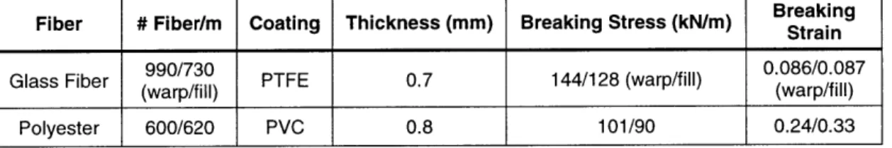
* Glass. Glass fibers have very high values of modulus of elasticity and tensile strength, but are also very brittle. By encasing the fibers in a flexible matrix, it is possible to take advantage of their high strength. However, the fabric is still subject to damage from repeated flexure or excessive bending during handling and installation. For this reason, glass fabrics are usually used for permanent structures or those that do not have to be erected repeatedly. Glass is not subject to UV degradation, making it a prime candidate for permanent installations. Uniaxial strength properties are given in Table 3.1 for polyester and glass fibers for comparison.
Table 3.1 Typical uniaxial breaking strength of glass and polyester fibers.
Fiber # Fiber/m Coating Thickness (mm) Breaking Stress (kN/m) BreakingStrain
990/730 0.086/0.087
Glass Fiber (warp/fill) PTFE 0.7 144/128 (warp/fill) (warp/fill)
(warp/fill) (warp/fill)
Polyester 600/620 PVC 0.8 101/90 0.24/0.33
* Aramids (Kevlar). Aramids are an organic material that have a high modulus of elasticity and breaking strength. They can withstand considerably more flexing than glass but not as much as nylon or polyester. However, aramids are subject to deterioration from UV light, and thus have not been widely used in membrane structures compared to glass fibers.
3.3
Coatings
There are many materials that have been used as coatings in membrane structures. The ones listed below are the most widely used because of their superior performance, cost, and ease of application.
* Polyvinylchloride (PVC). PVC is a soft and pliable material, enabling it to conform to the shapes required to membrane structures. It is resistant to UV light and is available in practically any color. It is most commonly used with nylon or polyester fabrics [12].
* Polytetrafluoroethylene (PTFE or Teflon). PTFE is chemically inert, resistant to moisture and microorganisms, and has low deterioration with age [12]. It is currently only available in white, but work is in progress to create different shades of PTFE. The main drawback is that much care must be taken so as to avoid damaging the fibers, and is more expensive than PVC-coated polyester. It is flame resistant and has a high tensile strength and modulus of elasticity.
* Silicone. Similar to PTFE, silicone has excellent characteristics of UV resistance, long-term flexibility, flame resistance, tensile strength, and modulus of elasticity. It is used as a protective coating for glass, and has high light transmission.
Toppings. Dirt and other pollutants, in addition to producing negative aesthetic and translucency characteristics, can increase the degradation rate of a fabric. One of the ways to protect the fabric coating is by giving it a surface coating or topping [12]. This topping not only serves to protect the fabric from UV light, but also to improve its self-cleaning characteristics. One such material is Tedlar, a polyvinylflouride (PVF), and is applied to both PTFE-coated fiberglass and PVC-coated polyester membranes.
3.4
Membrane Properties
The three most important properties of interest to designers regarding membrane structures are:
1. Short-term structural properties (determined mainly by the membrane material). 2. Long-term structural properties (how the properties are maintained over time and
under cyclic loading).
3. Non-structural properties (e.g. translucency, resistance to fading, etc.).
These properties are summarized for the two most commonly used membranes in Table 3.2 at the end of the chapter.
SHORT TERM STRUCTURAL PROPERTIES
Tensile strength: The resistance to failure under load of a membrane material must be high enough to enable the fabric to maintain the stresses from pre-stressing and external loads. Both PVC-coated polyester and PTFE-coated fiberglass can be produced with
strengths of up to 16 tons per meter width [16].
Tensile modulus: Higher modulus is a double-edged sword in that it can resist deformations under higher loads, but it also resists being molded to the prescribed structural profile. The latter makes the accuracy of cutting and installation of the membrane much more critical. Woven polyester fabrics have a medium modulus, are
easy to use, and their relative flexibility is normally not a problem from a structural point of view, except where large snow loads are expected [16]. Woven glass membranes have a high modulus of elasticity, but carry a risk of wrinkles, creases and sags if the cloth does not fit the site profiles exactly.
Tear strength: Most membrane failures are due to tearing, rather than by direct tensile failure, making tear strength and resistance to tear propagation a critical factor in selecting a fabric. PVC-coated polyester has medium tear resistance, whereas PTFE-coated glass has a high tear resistance [16]. Reinforced films have lower tear strengths than either of these materials, and plain films have the lowert tear strength of all.
Directionality: If isotropic material behavior is required for a given application, then only non-woven films may be used. Most woven fabrics display anisotropic characteristics, being stiffer in the warp direction than in the fill or weft, but this discrepancy is becoming smaller or even negligible with modem weaving and coating techniques (although still a cost premium). This technique consists of tensioning the fill
as well as the warp fibers during weaving.
LONG TERM STRUCTURAL PROPERTIES
Construction stretch: All woven membranes undergo some non-recoverable initial stretch during construction as the "crimp" is pulled out with the pre-stressing. The degree of stretch will be much greater in the undulating fill or weft direction than in the warp direction, and appropriate considerations should given to this property of the fabric during patterning. The membrane manufacturer supplies this data. This difference in stretching can be reduced by the weaving technique described earlier, or by pre-stretching the cloth before installation, thereby reducing the amount of stretch which occurs in the membrane during its lifetime.
Dimensional stability: The dimensional stability for woven fabrics (resistance to creep, deformation due to thermal or moisture conditions) under long term loading depends
more on the basic material than on the type of weave or coating [16]. Such deformations are undesirable in permanent structures, since they cause a loss of pre-stress. Polyester fabrics are relatively stable in terms of thermal and moisture conditions, but the creep is such that half of the pre-stress may be lost in the first ten days, a further half over the next hundred, and yet another half over the next thousand. This loss of pre-stress makes the need for re-stressing necessary after a certain period of time. Glass fabrics, on the other hand, have high dimensional stability.
NON-STRUCTURAL PROPERTIES
Translucency: In woven fabrics, translucency depends on the translucency of the fibers, coating material, and the spacing between the fibers. All three of these properties can be varied in order to obtain the desired translucency, while meeting other design criteria. PVC-coated polyester cloths may have translucencies of 8 to 30%, and PTFE-coated glass fabrics from 5 to 15%. The translucency of films depends on both the basic material and the coating,, and are available from almost 100% transparency to complete opacity.
Table 3.2 Properties of the two fabrics most commonly used for membranes [16].
PROPERTY FABRIC
Short term structural properties
Tensile strength Tensile modulus Tear strength Directionality
Long term structural properties
Construction stretch Dimensional stability Non-Structural properties Durability Translucency Appearance Ease of Installation Flexibility Jointing Summary PVC-COATED POLYESTER Medium Medium Medium
Stiffer in warp than weft, but there are fabrics available with virtually identical properties in
both directions.
Medium Medium
Lifetime normally 10 to 12 years,
depending on the exposure and opacity of coating. Design life could be only 3 to 5 years with highly translucent coatings and up to 15 years with opaque coatings. A white finish will reduce surface temperature and enhance durability.
8% to 30%
All colors available. Can be opaque or translucent. Suffers from dirt retention so that visual rather than physical
deterioration is likely to determine working life.
High, making for easy
fabrication, transportation, and installation.
Easily done.
Overall the most popular coated fabric, and there are many experienced installers. Cheap enough to re replaced every 10 years to maintain pristine appearance.
PTFE-COATED FIBERGLASS
High High High
Similar properties to PVC-coated polyester.
Low High
25 years or more.
5% to 15%
White and a few other colors are available. Dirt is not retained and surface remains clean. No discoloration occurs during lifetime.
Low, creating a risk of damage during fabrication,
transportation, or installation. Accurate cutting and installation vital.
Special techniques needed.
Used for membrane structures where long life and/or low maintenance are more important than low cost or ease of
SECTION
II
CHAPTER 4
FORM DETERMINATION
4.1 Basic Design Principles
Many designers are attracted to membrane structures because of the wide range of forms that can be created. The range of possible forms is extensive, yet these structures are by no means "free-form" structures. They must rigorously conform to the physical principles that govern their behavior as limited by the characteristics of the materials from which they are built [12]. The only way that a thin, flexible membrane can be made sufficiently stiff and flutter-proof when subjected to external loads is by the appropriate combination of curvature and pre-stressing.
TENSILE BEHAVIOR
The purpose of the pre-stressing in a membrane is to ensure that the fabric remains in tension, and therefore stable, even after the application of non-uniform loads such as wind or suction [16]. The basis for membrane structure design is to explore and exploit the nature of tensile behavior. Membranes are generally composed of numerous linear tension components, which act as tension surfaces both structurally and visually. Because membranes have negligible compressive, flexural and transverse shear strength, the applied loads must be resolved in their surface. Cables may be used to establish membrane boundaries or to reinforce a membrane by dividing the surface into smaller portions [12].
The elements supporting the membrane structure such as masts, arches, and perimeter beams, typically have significantly larger compressive, flexural and shear strengths. Although membrane structures are usually designed to highlight the structural elements used to carry tensile loads, this effect is amplified by the juxtaposition of the
tensile, compression, and bending components that support the membrane or surrounding structures.
GEOMETRICAL REQUIREMENTS
Surfaces are generally classified by their curvature. For cones and cylinders, one of their two curvatures has an infinite radius, and so they are classified as only having one curved direction on their surfaces. Tensile structures have two curvatures at each point on their surface of similar radius of curvature. Synclastic surfaces have double curvature, but in the same direction (or equal Gaussian sign curvatures), whereas anticlastic surfaces have their principal curvatures in opposite directions. This geometry allows the surfaces to resist a given loading condition in any direction, whereas a dome or synclastic surface can only resist loading in one direction (e.g. positive pressure in pneumatic structures). This principle is illustrated in Figure 4.1. Figure 4.1a and 4.1b show how the cable geometry is only stable for loading in one direction, but becomes unstable if the load direction is reversed. In Figure 4.1c, the system remains stable under any loading condition.
(a)
Unstable
Unstable
C Unstable D
Point P is stable against forces in this direction
Stable
D
Stable
Figure 4.1 Point P is stabilized against external forces from all direction is restrained by two tension members A-B and C-D acting in opposing directions [16].
The simplest example of this principle is the saddle shape membrane structure, such as the music pavilion in Figure 1.3, where a square membrane is stabilized with two high points and two low points. A schematic of this structure is given in Figure 4.2.
Figure 4.2 A four-point saddle shape created by two high points, and two low points.
When deciding on the geometry of the membrane structure, the following guidelines should be considered [16]:
* The greater the curvature of a given surface, the more effective the pre-stressing becomes at providing surface stiffness and preventing flutter.
* Counteracting the previous point, excessive curvature can make for practical difficulties in pre-stressing, especially with stiff materials such as PTFE-coated fiberglass membranes. These fabrics resist deformation and do not allow the fabric to redistribute local overstressing.
* Curvature distribution across the entire membrane should be relatively uniform, as large variations can lead to "soft" areas in some places, and stiff areas in others. This
High
High
could lead to excessive flutter of some areas, and even membrane failure under certain loading conditions.
GENERAL DESIGN PROCEDURE
Although the design of membrane structures cannot be reduced to a strictly linear sequence of tasks, the following general stages should be included in the design process [16].
* Finding a suitable geometrical form. * Deciding a workable pre-stressing method.
* Testing the proposed structure for stability under all loading conditions. * Dimensioning the parts (fabric and cables) for manufacture.
* Finalizing choice of materials and finishes.
For the conceptual design of membrane structures using both physical and computer modeling, the flowchart in Figure 4.3 is very effective. These steps will be explained in detail along with examples, but only general aspects of the steps that follow the conceptual design of a membrane structure (patterning, joint design, etc.) will be discussed. Using the design criteria mentioned in this section, the method of form-finding a working membrane shape and pre-stress can be done by physical and/or computer modeling.
Figure 4.3 Stages of a conceptual design process for a tension structure [16].
4.2
Physical Modeling
Unlike traditional framed structures, membrane structures are not easily drawn or sketched on a sheet of paper due to their complex geometry. The lack of a principal projection coordinate for stressed membranes makes it very difficult to experiment with forms on a two-dimensional plane, which is why 3D modeling is essential to the design process. Physical models are still a key part of the design process for membrane structures, although computer models are gaining popularity and reliability. With physical modeling, the designer can investigate the possibilities and limitations of tensile structures. However, to obtain a meaningful understanding of the actual behavior, the physical model must mimic the behavior of the prototypical structure [12].
Most tension structures have a near-uniform pre-stress throughout their membrane. For the special condition of uniform tension throughout the membrane, there are no shear stresses in the membrane, and the surface is minimized for a given set of
initial conditions. However, the "minimal surface" approach to designing membrane structures is not always practical. This is because a minimal surface is only an "ideal" solution for a specific set of loading parameters and pre-stressing, whereas the real structure will be subjected to a variety of static and dynamic loading conditions, and stress concentrations.
Soap and liquid plastic films are a minimal surface modeling media, and are very useful in investigating the limitations of uniformly stressed membrane surfaces. Liquids have tensile capacity, but no shear capacity. Soap films in wire or string frames will form the anticlastic shapes or pre-stressed structures, and the range of possible shapes with a uniform stress field can be explored by stretching the boundaries. Once an adequate shape has been found, photographs can be taken for measurement and scaling purposes. Figure 4.4 shows a typical soap film model.
Figure 4.4 Soap film model with an internal support.
Films can also be used to observe the performance of the membrane under applied loads by simply blowing on the film. The shape of the film will change in order to
maintain equilibrium. If a sufficiently high load is applied, the film will become synclastic and resemble a pneumatic structure. Threads can be used with soap films to model cable boundaries, the shape of which are determined by the length of the thread and the stress field of the film [12].
Nylon or other stretchy fabrics can also be used to model membrane structures, supported by thin cables or rigid masts. These materials will not have a completely uniform tension throughout their surface. The implications of high local tension can be studied by noting how uniformly the fabric is stretched, and how loose or wrinkled the fabric is in areas of low tension.
Both modeling materials are useful in exploring the range of possible shapes for a given set of boundary conditions, but should only be used for experimenting and not for final shape determination. This is because there are several significant differences between the models and the actual membrane materials used in tensions fabric structures. Structural membranes are not as flexible as liquid films, or even nylon fabric, and thus the final shape may be significantly different than that of the model.
4.3
Computer Modeling
Stemming from the need for more accurate form-finding of membrane structures, computer models have become increasingly popular. Currently, only a few software companies sale their code, and most membrane designers retain their programs as a market advantage. This report focuses on a commercially available membrane design and analysis program, called "EASY," sold by the German software company Technet-Gmbh.
INTRODUCTION TO COMPUTER MODELING
The analysis of tensile structures is a non-linear problem, and the stress-strain relationship of membrane materials is also highly non-linear. Fortunately, the stress-strain relation is nearly linear within the allowable stress range of most structural membranes [12], and are ignored in the analysis process. The deformations associated
with a given loading condition and pre-stress usually influence the resolution of those same forces, thus making load analysis a geometrically non-linear problem. Thus, the two stages of computer modeling can be summarized as follows:
* Formfinding: Formfinding is the process of determining the initial equilibrium shape for a given pre-stress condition. The computer finds a form that a 'pure' membrane would assume if stretched between the proposed boundaries with uniform tension in all directions.
* Analysis: The physical characteristics of the proposed membrane material and applied loads are fed into the computer, producing a modified equilibrium form. Stress and deflection magnitudes can then be checked.
Computer analysis of tensile structures is based on the assumption that it is possible to approximate the behavior of smooth surfaces by defining the geometry, material properties, and applied loads at discrete locations of the structure. As with most computer modeling, cables, membranes, compression struts and beams are divided into finite elements. These elements may correspond to the entire structural component or a portion of it, and are joined at nodes. The nodes are used to define the spatial geometry of the membrane, and may be restrained from translating or rotating. The individual elements are defined to have a certain elastic behavior, which can be defined to preserve a certain length or a certain force.
Because the thickness of membranes is very small relative to its other two dimensions, membrane structures are usually modeled using two-dimensional elements with different properties in the warp and fill directions. Uniaxial elements are much simpler to formulate and analyze than biaxial elements, and thus cable elements are usually used to model the membrane. There are several analysis techniques that utilize this uniaxial simplification (e.g. non-linear stiffness analysis, dynamic relaxation), but the Force Density method has proven to be extremely accurate, fast, and generates a smooth surface for practically any set of boundary conditions. EASY utilizes the force density method in its formfinding program, and non-linear stiffness analysis for its load-analysis program.