HAL Id: hal-00663243
https://hal.archives-ouvertes.fr/hal-00663243
Submitted on 26 Jan 2012HAL is a multi-disciplinary open access archive for the deposit and dissemination of sci-entific research documents, whether they are pub-lished or not. The documents may come from teaching and research institutions in France or abroad, or from public or private research centers.
L’archive ouverte pluridisciplinaire HAL, est destinée au dépôt et à la diffusion de documents scientifiques de niveau recherche, publiés ou non, émanant des établissements d’enseignement et de recherche français ou étrangers, des laboratoires publics ou privés.
DESIGN OF SANDWICH STRUCTURES WITH
CURVATURE
Vincent Manet, Han Woo-Suck, Vautrin Alain
To cite this version:
Vincent Manet, Han Woo-Suck, Vautrin Alain. DESIGN OF SANDWICH STRUCTURES WITH CURVATURE. ICCM 12, Jul 1999, Paris, France. pp.1062-1071. �hal-00663243�
DESIGN OF SANDWICH STRUCTURES
WITH CURVATURE
Vincent Manet 1, Woo-Suck Han 1, and Alain Vautrin 1
1
Materials and Mechanical Engineering Department, École Nationale Supérieure des Mines de Saint-Étienne, 158, cours Fauriel, 42023 Saint-Étienne cedex 2, France.
e-mail: {manet,han,vautrin}@emse.fr
SUMMARY: In this paper, we present a simple and efficient post-processing method in finite
element computations for the analysis of sandwich structures. This method is based on Reissner’s functional which is applied locally at interfaces between layers those mechanical properties are very different.
The method, valid in 2D as well as in 3D, is assessed in 2D for the computation of an U-type sandwich beam for which both the ratio of Young’s modulus of the skin to that of the core and the radius of curvature vary.
This example points out that the present method can be used for the design of complex structures based on finite element analysis owing to its numerical stability, i.e. its results remain accurate even using coarse meshes.
KEYWORDS: curved beams, finite element method, interlaminar stresses, post-processing
method, sandwich structures.
INTRODUCTION
The rise of interest for new materials in structural design leads to a real need of powerful analysis tools able to take their particular performances correctly into account.
The advantages of sandwich structures are nowaday well understood and they have already become important structural components in design, especially in the field of aeronautics. But progresses in polymer science and manufacturing processes have spread their use to a large range of situations (automotive industry, building construction...) because they yield more optimized sandwich structures in terms of mechanical performances, integration of functions as well as design shapes. Nevertheless, their numerical modeling still suffers from a lack of accuracy
A sandwich structure is a 3-layer laminated one, whose layers have very different geometrical and mechanical properties: the skins, which are generally thins and very stiff, work in membrane, while the core, which has low stiffness and density, is subjected to shear efforts. It
yields quite particular behaviour and failure modes (crack modes, instability modes, local denting...) [1]. The modeling based on classical finite elements (in displacements) leads to a poor accuracy of the force equilibrium at the interfaces between the skins and the core.
The main points which have to be fulfilled to get a correct modeling are the following:
• transverse shear effects are taken into account: this point is extremely important since the core is only subjected to shear loading;
• the continuity of displacements and the equilibrium state of stresses at each interface of layers must be satisfied;
• large differences of the geometrical and mechanical properties between layers are correctly modelled.
Among all the methods used to analyse the mechanical behaviour of structures, the finite element method is the preferred one, and among all the different elements, based on various principles, the most used ones still remain based on the displacement field. In order to propose an useful tool, we decided to focus on the development of a post-processing method, which could be used in conjunction with the classical displacement based finite element method, and therefore be easily implemented in existing programs.
The post-processing method should be simple enough to permit an easy implementation in existing software and take the aforementioned points into account, i.e. represents the shear behaviour of the sandwich plate in a more realistic way and respects the skin/core interface balance.
During the primary steps of the design process, i.e. when checking for different solutions, designers cannot use very time consuming models, and therefore use coarse meshes. Nevertheless, they need significant values of the design parameters in order to take right decisions. Within these quantities, the interlaminar stresses are of great importance in the design of structures making use of highly heterogeneous structures such as sandwiches. But such stress components can generally only be reached with very refined meshes. The aim of the present method is to yields accurate results even with coarse meshes.
POST-PROCESSING: ‘LOCAL REISSNER’ METHOD
Reliable stress values by finite element analysis can be achieved in different ways. When using mixed, hybrid or mixed-hybrid elements, stresses can appear as nodal unknowns which can then be found directly, but the number of nodal unknowns can be dramatically high. When classical displacements elements are used, a post-processing method is needed to recover stresses from the previously obtained nodal displacements. In this case, stresses are generally computed at Gauss points from which they are extrapolated to the nodes.
In this paper, we focus on the displacement based elements, which are the most used ones, and which are known, when using a classical post-processing method, to converge towards Reissner's solution [2]. Nevertheless, in this case a very fine and regular mesh must be used. The aim of the proposed improvement is to improve the convergence rate with respect to the mesh.
There are many different methods to compute stresses from the computed displacement field: the stress projection method, the least-squares minimization [3] which can all be performed globally (on the whole structure) or locally (within each element) [2].
The specific problem we face with sandwiches is to accurately compute stresses at interfaces between very different materials, but bonded together. We must keep in mind that only some components of these stresses must be continuous at interfaces as illustrated in Fig. 1 in 2D, where Ω1 and Ω2 are two regions of a given body, n the normal vector at interface and σσσσi the
stress vector
Fig.1: continuities at an interface
Hence, the simplest idea is to find the stress field directly using Reissner's formulation in each element, which means that nodal stresses are computed using the following relation:
{ }
τ =[ ] [ ]
−{ }
A 1 B q (1) with:[ ]
A = +∫
[ ]
Nσ T[ ]
S N[ ]
σ dΩ Ω (2)[ ]
B = +∫
[ ]
Nσ T[ ]
L N[ ]
u dΩ Ω (3) where[ ]
Nu and[ ]
Nσ the shape functions matrices for displacements and stresses respectively,[ ]
L the differential operator relating displacements to strains. Ω is the surface (or volume) of interest for the computation,{ }
q and{ }
τ the vectors of nodal displacements and stresses. The detail of the present method is presented in [4].It remains the choice of Ω in Eqns 2 and 3:
• When Ω represents the whole structure, then the method is equivalent to the use of Reissner’s mixed elements, where displacements and stresses are nodal unknowns. In this case, a large matrix is involved.
• When Ω is one element, then we have to average the results at nodes that belong to more than one element. This is generally a reliable method when material properties remain unchanged, but when we face a discontinuity in the material properties between two adjacent elements (one belonging to a skin, the other to the core for example), this averaging method only leads to accurate results if a regular and fine mesh is used.
σσσσi σσσσi n n Ω1 Ω2 Continuity: • of displacements Ui • of stress components σijnj i.e. continuity of interlaminar
For this reason, we chose a third way: to apply the Reissner’s formulation only where it is needed, in other words at the interfaces between the different layers. This means that we apply the aforementioned formulae on two adjacent elements located on each side of an interface:
Ω in Eqns 2 and 3 represents the volume (or surface) of two elements on each side of an interface, one belonging to a skin, the other to the core.
This method will be referred to as the ‘Local Reissner’ method. The main advantages of this method are that:
• only small matrices are involved in the computation;
• the stresses are directly computed at interfaces without averaging data, contrary to what is done in classical methods;
• the stress balance is fulfilled on the whole region containing the interface;
• the programming of the method and its implementation in existing finite element packages is simple: results given in the following have been obtained using a macro command implemented in the ANSYS v5.3 FEM package.
The elements used in this paper are Serendip 8 nodes quadrilaterals, i.e. quadratic shapes functions are used in both directions of the plane (we only present planar results for sake of simplicity).
ANALYSIS OF A U-TYPE BEAM
Presentation
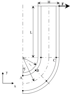
We propose to study an ‘‘U-type beam’’ illustrated in Fig. 2.
H=2 mm and L=20 mm are constants, but the radius Rint varies from 5 to 0.125 (leading to a
ratio R/H between 3 and 0.5625). This is the important point of the study since we know that decreasing this ratio is equivalent to getting closer to a singularity. The core represents 80% of the total height of this symmetrical sandwich.
The skins are made of unidirectionnal glass/epoxy T300-914 (E11s= 40 GPa, E22s = E33s = 10
GPa, ν12s = ν13s = ν23s = 0.3 and G12s = G13s = G23s = 4 Mpa).
The material properties of the core vary: νc=0.4 is constant, but Ec takes the following values:
3400 MPa (epoxy), 340 MPa (foam), 140 MPa (medium foam) and 70 MPa (soft foam). The applied lateral force is F=1 N/mm (the thickness of the beam is equal to 1 mm). By symmetry, only one half of the beam has been modeled.
In the following, arabic numbers ‘1’ and ‘2’ (instead of letters ‘x’ and ‘y’) stand for local coordinates system, where ‘1’ indicates the direction of the interface at the considered point, ‘2’ the orthogonal direction (for simplicity, we stay to 2D), whereas ‘x’ and ‘y’ denote global coordinate system.
A B C H L F
Fig. 2: U-type Beam
The characteristics of the meshes are the following:
• target: 2 elements through the thickness of each skin, 16 through the thickness of the core,
nrcuts longitudinal cuts for the inner quarter of circle, 2 nrcuts for the outer quarter of
circle, and ncuts longitudinal cuts for the length L.
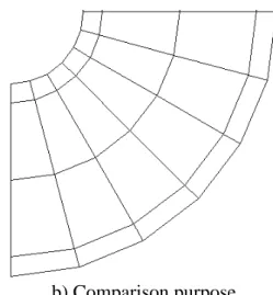
• comparison purpose: 1 element through the thickness of each skin, 2 through the thickness of the core, and nrcuts longitudinal cuts for both inner and outer quarters of circle, and
ncuts longitudinal cuts for the length L.
The values used for ncuts and nrcuts for different values of R/H ratio are given in Table 1. They yield meshes having the same shape as in Fig. 3.
Table 1: parameters of meshes
Rint R/H reference computation
ncuts nrcuts ncuts nrcuts
5 3 50 20 25 8 3 2 50 20 25 8 2 1.5 50 20 25 6 1 1 50 12 25 6 0.55 0.875 50 12 25 6 0.5 0.75 50 12 25 6 0.25 0.625 60 8 30 4 0.125 0.5625 60 8 30 4
Results and discussion
The points retained in this analysis are the points A, B and C shown in Fig. 2.
The results are presented in terms of interlaminar stresses at these points (σ22 and σ12) when
both material (ratio of Young’s moduli E11s/Ec) and geometrical properties (ratio R/H) vary. y
a) Target b) Comparison purpose Fig. 3: mesh of the quarter of circle (case Rint=0.75)
In the figures presenting the results (Figs. 4 to 8), the following legend is used:
0.9 0.9 5 1 1.0 5 1.1 1.1 5 3 0.75 0.7 1 1.3 1.6 1.9 2.2 2.5 2.8 3.1 3 2 1.5 1 0.875 0.75 0.625 0.5625
Fig. 4: σ22 /σ22tar at point A versus R/H ANSYS, E11s/Ec = 11.8 Local Reissner, E11s/Ec = 11.8 ANSYS, E11s/Ec = 118 Local Reissner, E11s/Ec = 118 ANSYS, E11s/Ec = 286 Local Reissner, E11s/Ec = 286 ANSYS, E11s/Ec = 571 Local Reissner, E11s/Ec = 571
σ
22/
σ
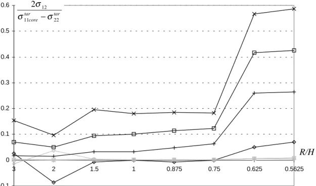
22 tar R/H up to 3.87-0.1 0 0.1 0.2 0.3 0.4 0.5 0.6 3 2 1.5 1 0.875 0.75 0.625 0.5625 Fig. 5: 2 12 11 22 σ σ core σ
tar − tar at point A versus R/H
0 2 4 6 8 10 12 14 3 2 1.5 1 0.875 0.75 0.625 0.5625 Fig. 6: σ22 /σ22 tar at point B versus R/H R/H R/H 2 12 11 22 σ σ core σ tar − tar σ22 /σ22 tar
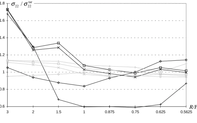
0.6 0.8 1 1.2 1.4 1.6 1.8 3 2 1.5 1 0.875 0.75 0.625 0.5625 Fig. 7: σ22 /σ22 tar at point C versus R/H -6 -5 -4 -3 -2 -1 0 1 2 3 4 5 6 3 2 1.5 1 0.875 0.75 0.625 0.5625
Fig. 8: σ12 /σ12tar at point C versus R/H
R/H
σ
12 /σ
12 tar R/H σ22 /σ22 tar -40.5 -8.97 12.5 10.3 7.37All these figures (4 to 8) illustrate the fact that the local Reissner method is not sensitive to singularities:
• Fig. 4 illustrates the fact that σ22 /σ22tar at point A remains close to one, even if it get a little bit worst when approaching the singularity, whereas ANSYS strongly diverges. The same conclusion can be drawn at point B (see Fig. 6).and at other points which are not reported in this study.
• Fig. 5 show that 2σ12/(σ11core σ22
tar − tar
) at point A is always close to zero, whereas ANSYS (least-squares and nodal averaging) diverges. This phenomenon is a little bit less sensitive at points located on the other side of the core, because the core damps it.
• Fig. 8 presenting σ12 /σ12 tar
at point C exhibits numerical problems for different values of
R/H ratio. These problems, which are encountered in the same way at others locations
(point B for example), are not present when using the local Reissner method, which gives stable results.
A complete study of a simply supported sandwich beam submitted to an uniform pressure on its top face and full comparison with ANSYS (in terms of mesh refinement, element types, influence of Es/Ec ratio) can be found in [5]. Others examples, such as a sandwich plate or an
adhesive joint, can be found for example in [4,6]. They all demonstrate the improvements brought by the local Reissner method: speed up of the convergence rate and numerical accuracy and stability.
CONCLUSIONS
In this paper, we have pointed out that the computation of stresses at interfaces can be improved by the local Reissner method. The computation cost of this method remains low, because it is only performed along interfaces, on two adjacent elements, where the displacement methods is not able to give good results.
The local Reissner method is particularly interesting when dealing with multi-layered structures having very heterogeneous mechanical and geometrical properties, such as sandwiches.
From the treated examples, we can conclude that the local Reissner method:
• improves convergence (which permits to use coarse meshes);
• is more stable;
• is more accurate.
It is also important to note its simplicity of formulation and of implementation, even in existing finite element programs.
The last point is that the present formulation can be applied every time that an interface between two different materials is encountered, the method having been shown to be particularly robust when the differences in the mechanical properties between the layers are very important.
The present method is an interesting tool for engineers involved in the design of structures using any highly-heterogeneous multi-layered materials such as sandwiches and adhesive
joints, but also any structure containing interfaces between materials having very heterogeneous mechanical properties.
REFERENCES
1. Teti, R. and Caprino, G., ‘‘Mechanical behavior of structural sandwiches’’, Sandwich
Constructions 1, Chameleon Press LTD. Ed., pp. 53-67, 1989.
2. Hinton, E. and Campbell, J.S., ‘‘Local and global smoothing of discontinuous finite element functions using a least squares method’’, Int. J. for Num. Meth. in Eng., Vol. 8, pp. 461-480, 1974.
3. Zienkiewicz, O.C. and Taylor, R.L., The Finite Element Method, Vol. 1, MacGraw-Hill, London, 1994.
4. Manet, V., Analysis Methods of Interfaces Stresses in Sandwich Structures by Finite
Elements (in french), Ph D thesis, Université B. Pascal - Clermont II, France, 1998.
5. Manet, V., ‘‘Using Ansys to calculate the behaviour of sandwich structures’’,
Composite Science and Technology, Vol. 58, No. 12, 1998, pp. 1899-1905.
6. Manet, V., Han, W.-S. and Vautrin, A., ‘‘Static analysis of sandwich plates by finite elements’’, Proceedings of the EUROMECH 360 Coloquium: Mechanics of Sandwich
Structures, Saint-Étienne, France, May 13-15, 1997, Vautrin, A. Ed., Kluwer Academic Press,